 Changjun Li1
 Junpeng Zou
- 1Zhejiang Institute of Communication Co., Ltd., Hangzhou, China
- 2Faculty of Engineering, China University of Geosciences, Wuhan, China
- 3School of Civil Engineering, Zhejiang University of Technology, Hangzhou, China
- 4Shaoxing Keqiao Transportation Investment and Construction Co., Ltd., Shaoxing, China
- 5School of Information Engineering, Wuhan Business University, Wuhan, China
In order to improve the prefabrication level of highway mountain tunnels, improve the quality of the project, and shorten the construction period, a new type of prefabricated concrete curb member was developed based on an actual project. The production process, construction technical points, and on-site assembly technology are discussed. In addition, a method to calculate the anti-collision performance of the curb components is proposed, that is, the collision force of 850 kN was calculated by the pseudo-static method, and then finite element simulation analysis was used to obtain the stress of the concrete structure and reinforcement. The results show that the reinforcement will not fail, which will ensure the curb component will not undergo brittle fracture. This study provides a reference to improve the prefabrication level of highway tunnels.
Introduction
In recent years, prefabricated structures have been widely used after the promotion of the Chinese government related to the conservation of resources, reduction of construction pollution, and improved labor safety. This might enhance the deep integration of the construction industry with information technology and industrialization, foster new industries and new driving forces, as well as dissolve excessing capacity. In the field of tunnel and underground engineering, prefabrication technology has been widely used for shield tunneling. It has been applied in cut-over highway tunnels (Jiang, 2018), municipal facility tunnels (Kuang et al., 2022), cable culverts (Tao, 2018), and other fields. However, the range of prefabricated components used in drill-blast road tunnels is low. The main and auxiliary structures of prefabricated components are still primarily cast-in-place, including curb components. The structure size is generally fine and the wall thickness is mostly between 10 and 15 cm. It is difficult to ensure the construction quality of site erection formwork pouring, which frequently leads to a rough surface on the side groove, poor drainage, debris deposition, cracking and missing angles (Wang et al., 2018), and an uneven road surface (see Figure 1). Moreover, the site erection template has poor construction efficiency and requires a long construction period.
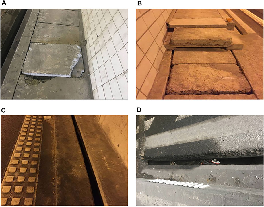
FIGURE 1. Photos of damaged traditional curb components: (A) cover plate missing corners, (B) flatness of cover plate is poor, (C) slotted ditch above the road surface, and (D) debris clogged up in a slotted ditch.
However, curb components are the most easily damaged parts in a tunnel because vehicles deviate from the lane and collide with them. Accident severity is generally high (Bassan, 2016) and there is a risk of fire, although the frequency of collisions in a tunnel is lower than on roads outside the tunnel. Pervez and Caliendo et al. conducted statistical and predictive research on the collision frequency in tunnels (Caliendo et al., 2013, 2016, 2019; Pervez et al., 2020, 2021; Tang et al., 2022). This problem needs to be studied to improve the durability of tunnel structures and avoid traffic interruptions due to damaged curb components. However, there is still a gap in the anti-collision performance requirements and checking calculation methods of curbs in China’s code for highway tunnel design. In light of the above, it is essential to investigate vehicle-bridge collisions based on the existing achievements. Cao et al. (2019) and Heng et al. (2021) studied the collision of heavy trucks against the bridge caps and piers of cross-line bridges. High-fidelity finite element analysis by Oppong et al. (2021)was used to assess the impact of ultra-tall vehicles on the main girder. Thilakarathna et al. (2010) used a nonlinear numerical analysis model to research the impact of vehicles on piers and columns, and obtained analysis results of the impact force time-history curve, structural displacement, and reaction force. Based on refined nonlinear finite element analysis, Xu et al. (2012) studied the damage mechanism of a bridge superstructure and reported a time history of impact force when over-height vehicles collided with curb components.
In this paper, a new type of precast concrete curb component for highway tunnel was proposed to improve the precast level of highway tunnel structures by drilling and blasting. A pseudo-static method and finite element modeling were used to calculate the impact load and check its anti-collision performance. Finally, the key technologies and engineering applications of its construction are introduced to provide a reference for improving the prefabrication level of highway tunnels.
Design of tunnel curb components
Curb components usually include a side ditch, side stone, cable trench, and cover plate. Cover plates are usually prefabricated components. Among these components, the side ditch and side stone need to be considered for construction technology.
As shown in Figure 2, there are two common kinds of roadside ditches, the slotted ditch and blind drainage, each with its own characteristics: the slotted ditch is easy to install and does not require bottom and slurry processes. However, the construction of blind drainage is more difficult, including paving of the asphalt pavement at the edge, resulting in an uneven pavement surface, which is prone to water accumulation.
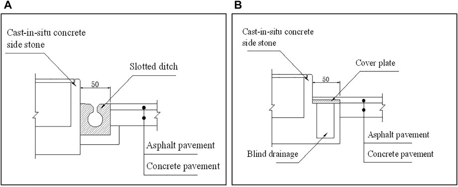
FIGURE 2. The tunnel curb components: (A) slotted ditch, (B) blind drainage.
In contrast, a slotted ditch is superior and is more commonly used on highways in Zhejiang province. However, the following problems remain:
1) It is difficult to clean the slotted ditch, which increases the maintenance difficulty of the highway operating unit;
2) Due to the infiltration of groundwater into the asphalt and concrete pavement in the tunnel, it is difficult for the slotted ditch to drain the interlayer water under the asphalt surface;
3) Because the width of the slotted ditch is 50 cm, it can invade the carriageway pavement.
Figures 3, 4 show a three-dimensional structural drawing of the integral curb components (i.e., a slotted ditch component that prefabricates the side stones and side ditch together), with a size of 65 × 86 × 100 cm, a segment length of 1 m, and mass for each segment of 612.25 kg.

FIGURE 3. Three-dimensional structural drawing of the integral curb components.
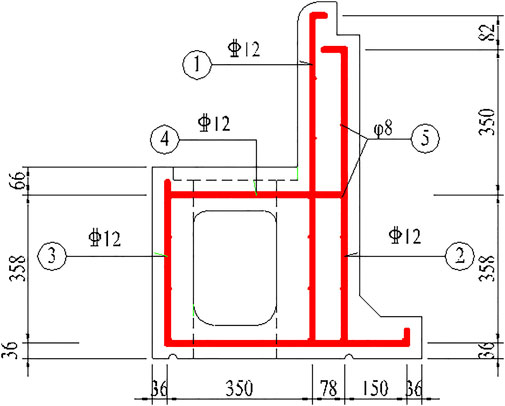
FIGURE 4. Design of the side stone and side ditch, and detailed drawing of the reinforcement.
To improve the shear resistance between segments, they are connected by tension, which is better and smoother than the current cast-in-situ concrete curb components. The width of the ditch is 35 cm, which effectively ensures the road surface of the driveway. Compared with the previous curb components, the maintenance cost of prefabricated curb components is lower, that is, the ditch top of the prefabricated curb components is equipped with a drainage ditch (that quickly drains the tunnel pavement water) and a flushing hole (that effectively dredges debris blocking the ditch). The grate on the sand sediment trap in the middle of the side ditch collects debris and three drainage holes arranged symmetrically on the ditch side of the prefabricated curb components allow seepage to discharge to the asphalt layer. According to the actual engineering situation, the arrangement of the drainage holes can also effectively prevent groundwater from infiltrating into the asphalt and concrete pavement layers.
Calculation of anti-collision performance
Common check calculation methods
The impact process is a transient dynamic action, and engineering often converts the dynamic action into a static load for design. Commonly used equivalent static calculation methods include: the global average method, local average method, and equivalent displacement method. According to previous studies, when a vehicle’s speed is 80 km/h, the displacement method has the greatest accuracy to calculate the equivalent static force. The equivalent impact force is determined by:
where
China’s “General Specifications for Design of Highway Bridges and Culverts” (JTG D60-2015) stipulates that the state of vehicle impact should be calculated for bridge piers subjected to vehicle impact without anti-collision measures. The impact force along the vehicle direction should be 1000 kN, the impact force perpendicular to the driving direction of the vehicle should be 500 kN, and the two equivalent forces should be considered at different times.
The “Design Specifications for Highway Safety Facilities” (JTGD 81–2017) adopts the pseudo-static method to solve the collision force of a car on the guardrail. The pseudo-static method adopts the assumptions of average speed, rigid car and guardrail, and average acceleration.
The lateral displacement of the car can be expressed as:
where
The lateral average speed is determined by:
where
The time required for lateral displacement is determined by:
The lateral acceleration of the car is determined by:
Then, the lateral collision force can be obtained as:
Assuming that the stiffness of the car and the guardrail is a linear spring, the relationship between the collision force and time is a sine curve, and the maximum lateral acceleration of the car is determined by:
Then, the maximum lateral collision force is determined by:
Adding the dynamic correction coefficient to the above formula, the calculation formula of the lateral collision force can be obtained as follows:
This calculation method for the collision force takes into account factors including vehicle size and collision angle, and is more suitable for calculating the collision force from different vehicles; however, it ignores the deformation of vehicles and piers. In actual situations, the car in the collision process often undergoes deformation. Therefore, the calculation results may be different from the actual value.
Finite element modeling
In this study, we used the instantaneous impact force, equivalent static force, and pseudo-static force to calculate the anti-collision energy of curb component side stone structures. The simulation setting speed was 80 km/h, the oblique impact angle was 20°, and the body weight was 8 t. Formula (9) shows that the lateral impact force obtained using the pseudo-static method was 850 kN, which is greater than the 500 kN recommended by The General Code for Highway Bridge design (JTG D60-2015); therefore, the former value was used as a conservative estimate.
For specific materials related to the concrete and reinforced materials, see Tables 1, 2.

TABLE 1. Material parameters of concrete.
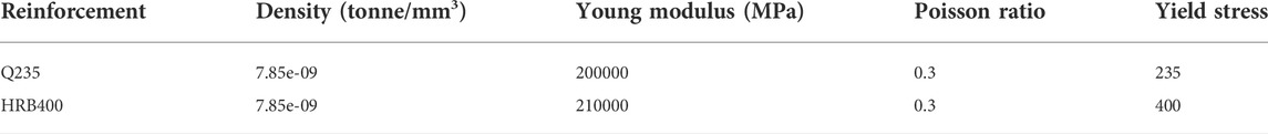
TABLE 2. Material parameters of reinforcement.
Figure 5 shows the geometrical model and the finite element mesh of the parts of the curb components. The force of the friction and the friction formula are Lagrange multipliers, and the model’s plat and integral curb component side stones and side ditches adopt physical units, the top of which adopts the “hard contact”. There is a 5 mm reserved space at the lap joint of the cover plate. In order to reduce integral and hourglass control, the grid cell of the integral curb component side stones and side ditches contains a ten-node quadratic tetrahedral element (C3D10), whereas the cover plate and segment components contain an eight-node linear hexahedral element (C3D8R). Standard model test piece concrete contains C35. The main reinforcement type is φ12 mm HRB400, whereas the distributional reinforcement was φ8 mm HPB235. The steel bar uses a line element, and the mesh element type is a two-node linear three-dimension truss element (T3D2). The interaction of the “built-in zone” means the reinforcement and concrete are completely fixed regardless of the slip between the reinforcement and concrete.
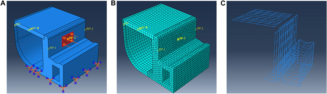
FIGURE 5. A geometrical model and finite element mesh of the curb component parts: (A) geometrical model, (B) finite element mesh, and (C) rebar.
Boundary conditions and loadings
According to the installation method of the curb components, the bottom of the side stone and side ditch of the curb component is the fixed end (i.e., the displacement is 0). According to the wheel load area distribution table in the “General Specification for Highway Bridges and Culverts Design” (JTG D60-2015), a rectangular area of 0.3 m × 0.2 m is used, to which a uniform force of 14.2 MPa is applied, as shown in Figure 5.
Results
Figure 6 is a sketch map of the calculation results of maximum principal stress and reinforcement stress of the concrete structure.
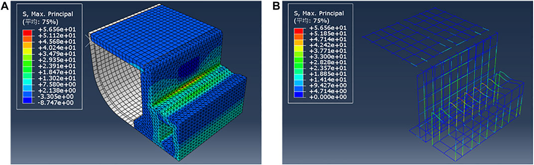
FIGURE 6. Results of finite element analysis: (A) maximum principal stress of concrete structure (MPa), (B) reinforcement stress (MPa).
The joint of the side stone and side ditch is a right-angle structure that has large tensile stress after bearing the force of an impact. When the axial tensile strength of C35 concrete exceeds 2.20 MPa the concrete will crack. However, the maximum tensile stress of the steel bar is about 56 MPa (i.e., the steel bar will not be damaged); therefore, a brittle fracture of the curb components will not occur.
The maximum displacement of the member (i.e., the displacement of the top of the side stone) was 1.34 mm, and the displacement generated by the collision position was 7.8–8.5 mm. The specific displacement after a collision with the components is shown in Figure 7.
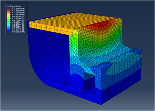
FIGURE 7. Displacement cloud map (MPa).
Construction of prefabricated curb components
The construction process of prefabricated road edge components is shown in Figure 8. The concrete design strength was C35, the segmental length was 1 m, the recommended mix ratio was cement:sand:gravel:fly ash:water:admixture = 270:850:1000:90:160:1.8, and the slump should be controlled at 5–7 cm. The precast concrete drainage ditch forming process used an attached vibration platform. The concrete pouring height of each layer should not exceed 300 mm.

FIGURE 8. Construction process of the prefabricated curb components.
In general, the first vibration time was 60—80 s, the second vibration time was 30—40 s, and the interval time between the two vibrations was 60—90 s. After finishing the plastering process, a non-woven geotextile was sprayed with water cover. After the surface concrete was finally solidified, spray maintenance was performed. Under a high temperature, the spray was performed every 30 min in the daytime for 5 min, and every 1 h at night for 5 min. The spray maintenance was performed for 5 d, and the cover maintenance was performed for 7 d. Demoulding was performed when the concrete strength reached 75% or more of the design strength (see Figure 9).
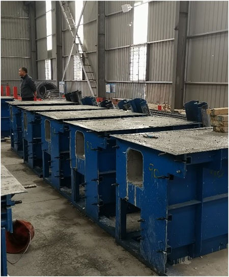
FIGURE 9. Molds for prefabricated curb components.
The assembly process was performed and hoisted by small machinery. The installation position was laid out and flatted, and mortar was used for the secondary level before installation. In order to ensure the assembly accuracy of the components, site lofting was performed before the assembly.
Engineering application
Through careful design and construction, this new type of prefabricated road component has been successfully used in the mountain tunnels of many highways in Zhejiang Province. The cumulative length exceeds 10 km. Compared with the original pouring road edge component, this new prefabricated road component is a big improvement (Figure 10).
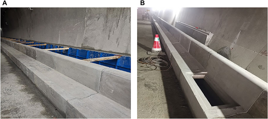
FIGURE 10. Pictures of prefabricated curb components at a construction site: (A) side ditches and side stones, (B) sand sediment trap.
Conclusions
This study developed new prefabricated curb components for highway mountain tunnels, which have the advantages of centralized prefabrication, component standardization, and commercialization. The prefabricated construction method allows the factory prefabrication of structural components ahead of or parallel to the excavation time of the corresponding parts in the tunnel, saving the implementation time of the linear construction process in the tunnel. Prefabricated curb components overcome the disadvantages related to the quality of the traditional slotted ditch, which is difficult to control, and improve the accuracy of field construction.
In addition, this study presents a method of calculating the collision-proof energy of the prefabricated curb components. The impact force of vehicle side rock in operation, which was 850 kN, was calculated using a pseudo-static method. The stress on the concrete structure and steel bar obtained by finite element simulation was analyzed, and the results showed that no brittle fracture would occur in prefabricated curb components after a collision.
Data availability statement
The original contributions presented in this study are included in the article/Supplementary material, and further inquiries can be directed to the corresponding author.
Author contributions
Investigation, CL and JZ; methodology, WH and XD; writing-original draft preparation, CL and GZ; writing-review and editing, YZ and MW. All authors have read and agreed to the published version of the manuscript.
Funding
This work was supported by the China National Natural Science Foundation (Nos. 42177152 and 41902293), the Guiding Project of the Scientific Research Plan of the Hubei Provincial Department of Education (No. B2021272), and Doctoral Fund of Wuhan Business University (No. 201908214).
Conflict of interest
CL is employed by Zhejiang Institute of Communication Co., Ltd. and XD is employed by Shaoxing Keqiao Transportation Investment and Construction Co., Ltd.
The remaining authors declare that the research was conducted in the absence of any commercial or financial relationships that could be construed as a potential conflict of interest.
Publisher’s note
All claims expressed in this article are solely those of the authors and do not necessarily represent those of their affiliated organizations, or those of the publisher, the editors, and the reviewers. Any product that may be evaluated in this article, or claim that may be made by its manufacturer, is not guaranteed, or endorsed by the publisher.
References
Bassan, S. (2016). Overview of traffic safety aspects and design in road tunnels. IATSS Res. 40 (1), 35–46. doi:10.1016/j.iatssr.2016.02.002
Caliendo, C., De, G., and Guida, M. (2013). A crash-prediction model for road tunnels. Accid. Analysis Prev. 55, 107–115. doi:10.1016/j.aap.2013.02.024
Caliendo, C., De, G., and Guida, M. (2016). Comparison and analysis of road tunnel traffic accident frequencies and rates using random-parameter models. J. Transp. Saf. Secur. 8 (2), 177–195. doi:10.1080/19439962.2015.1013167
Caliendo, C., De, G., and Russo, I. (2019). Analysis of crash frequency in motorway tunnels based on a correlated random-parameters approach. Tunn. Undergr. Space Technol. 85, 243–251. doi:10.1016/j.tust.2018.12.012
Cao, R., Agrawal, A., El-tawil, S., Xu, X., and Wong, W. (2019). Heavy truck collision with bridge piers: Computational simulation study. J. Bridge Eng. 24 (6), 04019052. doi:10.1061/(asce)be.1943-5592.0001398
Heng, K., Li, R., Li, Z., and Wu, H. (2021). Dynamic responses of highway bridge subjected to heavy truck impact. Eng. Struct. 232, 111828. doi:10.1016/j.engstruct.2020.111828
Jiang, H. (2018). “A summary of precast technology application in tunneling,” in Proceedings of the proceedings of GeoShanghai 2018 international conference: Tunnelling and underground construction (Singapore: Springer Singapore).
Kuang, Y., Peng, Z., Yang, J., Zhou, M., He, C., Liu, Y., et al. (2022). Physical and numerical simulations on mechanical properties of a prefabricated underground utility tunnel. Materials 15 (6), 2276. doi:10.3390/ma15062276
Oppong, K., Saini, D., and Shafei, B. (2021). Characterization of impact-induced forces and damage to bridge superstructures due to over-height collision. Eng. Struct. 236, 112014. doi:10.1016/j.engstruct.2021.112014
Pervez, A., Huang, H., Han, C., Wang, J., and Li, Y. (2020). Revisiting freeway single tunnel crash characteristics analysis: A six-zone analytic approach. Accid. Analysis Prev. 142, 105542. doi:10.1016/j.aap.2020.105542
Pervez, A., Huang, H., Lee, J., Han, C., Wang, J., and Zhang, X. (2021). Crash analysis of expressway long tunnels using a seven-zone analytic approach. J. Transp. Saf. Secur. 13 (1), 108–122. doi:10.1080/19439962.2019.1605642
Tang, Z., Wu, Z., and Zou, J. (2022). Appraisal of the number of asperity peaks, their radii and heights for three-dimensional rock fracture. Int. J. rock Mech. Min. Sci. 153, 105080. doi:10.1016/j.ijrmms.2022.105080
Tao, L. (2018). Research and analysis on construction technology of precast square culvert component in cable tunnel. Build. Technol. Dev. 45 (6), 49–50.
Thilakarathna, H., Thambiratnam, D., Dhanasekar, M., and Perera, N. (2010). Numerical simulation of axially loaded concrete columns under transverse impact and vulnerability assessment. Int. J. Impact Eng. 37 (11), 1100–1112. doi:10.1016/j.ijimpeng.2010.06.003
Wang, Y., Zhou, X., Wang, Y., and Shou, Y. (2018). A 3-D conjugated bond-pair-based peridynamic formulation for initiation and propagation of cracks in brittle solids. Int. J. Solids Struct. 134, 89–115. doi:10.1016/j.ijsolstr.2017.10.022
Keywords: highway tunnel, curb component, crashworthiness, pseudo static method, finite element method
Citation: Li C, Zou J, He W, Ding X, Zheng G, Zhuang Y and Wang M (2022) Study on anti-collision behavior of new precast concrete curb components in a highway tunnel. Front. Earth Sci. 10:931071. doi: 10.3389/feart.2022.931071
Received: 28 April 2022; Accepted: 04 July 2022;
Published: 23 August 2022.
Edited by:
Shibing Huang, Wuhan University of Science and Technology, ChinaReviewed by:
Jianxin Yu, Henan Polytechnic University, ChinaYong Fan, China Three Gorges University, China
Copyright © 2022 Li, Zou, He, Ding, Zheng, Zhuang and Wang. This is an open-access article distributed under the terms of the Creative Commons Attribution License (CC BY). The use, distribution or reproduction in other forums is permitted, provided the original author(s) and the copyright owner(s) are credited and that the original publication in this journal is cited, in accordance with accepted academic practice. No use, distribution or reproduction is permitted which does not comply with these terms.
*Correspondence: Junpeng Zou, em91anVucGVuZ0BjdWcuZWR1LmNu