 Qingli Zhu1
 Yanping Ding2*
- 1The Third Engineering Co., Ltd. of China Railway 20th Bureau Group, Chongqing, China
- 2Chongqing Jiaotong University, Chongqing, China
The rapidly expanding transportation hub system in China has driven a large number of track and highway engineering projects nationwide, resulting in increasing interchanges of highway and railway tunnels year on year. The mutual impact between new and existing tunnels is one of the most important topics in geotechnical engineering. Constructed undercrossing, an existing highway tunnel is commonly seen in new railway tunnel projects. The new railway tunnel excavation will affect the stability and safety of the existing highway tunnel. Our study takes the newly built Huilongwan Railway Tunnel section undercrossing the existing Longzhouwan Highway Tunnel, one of the East Ring Line Projects of Chongqing Railway Terminal, as the object. This article simulated the displacement changes and structural deformation pattern of the existing highway tunnel caused by the excavation of the new railway tunnel with finite element analysis software and compared them with on-site measurements one by one to clarify the impact of new railway tunnel excavation on the stability of the existing highway tunnel. The result proved that the non-blasting excavation with a three-step temporary invert method could ensure the safety of the existing highway tunnel.
1 Introduction
In recent years, the rapidly developing Chinese economy has boosted the constructions of transport infrastructure. Underground engineering is one of the construction projects that challenges geotechnical safety. When constructing such infrastructure in the urban area, there are so many adjacent constructions sites that the tunnels have to be built interchanging with existing ones (Liu et al., 2010; Chen et al., 2015; Gui, 2019; Yang, 2019). Due to the narrow interval space between the existing and the new, the excavation and support of the new tunnel may cause the existing tunnel to be displaced and deformed, threatening the structural stability. Currently, there are no official specifications and guidelines for intercrossing engineering, so most projects depend on their previous design and construction experience (Tian, 2006; Li et al., 2012; Li et al., 2013; Leng et sl., 2014). This article takes the section of the new Huilongwan Railway Tunnel undercrossing the existing Longzhouwan Highway Tunnel, one of the East Ring Line Projects of Chongqing Railway Terminal, as the object of study. We simulated the displacement change and structural deformation pattern of the existing highway tunnel caused by the new railway tunnel excavation with finite element analysis software. We also compared them with on-site measurements one by one to clarify the impact incurred by the new railway tunnel excavation on the existing highway tunnel stability and diagnosed the influence degree and stability of the existing highway tunnel. Based on these studies, this article will provide a theoretical basis for the support and reinforcement of engineering entities.
2 Project Overview
2.1 Overview of Huilongwan Railway Tunnel
The Huilongwan Railway Tunnel is 4,350 m long. The DK23 + 480∼DK23 + 580 section of the Huilongwan Railway Tunnel undercrosses the existing Longzhouwan No.2 Highway Tunnel with an 82° reverse intersection and a 5 m thick net stratum between its vault and the inverted arch of the existing highway tunnel.
Plane profile Figure 1 is shown as follows: (the bold line is the transit map of the Huilongwan Railway Tunnel; the reverse intersection between Huilongwan transit and the Longzhouwan Highway Tunnel is 82°).
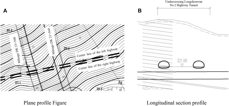
FIGURE 1. Tunnel diagram. (A) Plane profile figure. (B) Longitudinal section profile.
The longitudinal section profile Figure 1B is shown as follows: (the bold line is the transit map of the Huilongwan Railway Tunnel; the two cross sections above the bold line represent the Longzhouwan Highway Tunnel).
2.2 Longzhouwan No. 2 Highway Tunnel
The secondary lining of the Huilongwan Railway Tunnel section undercrossing the Longzhouwan No. 2 Highway Tunnel was completed with reinforced lining and reinforced steel. With 5 cm of deep reserved settlement space for subsequent new railway tunnel construction, the structures in this section form a closed loop.
2.3 Hydrogeological condition of the section
In the DK23 + 480 ∼ DK23 + 580 section of the Huilongwan Railway Tunnel, the wall rock of this section was designed as Level IV wall rock composed of sandstone according to the design data, tunnel surface disclosure, and tunnel geological projection results, while the Longzhouwan Highway Tunnel construction was designed at the same position as Level Ⅲ wall rock. The surrounding rock of the lower crossing section is mainly Xujiahe Formation sandstone, partially mixed with shale. The sandstone joint fissures are developed. The tunnel axis is roughly parallel to the stratum trend, and the rock stratum is steep. The surrounding rock of the tunnel body is easily deformed due to shallow burial, collapse, and the left side of the surrounding rock of the tunnel body is biased The water outflow form of the tunnel is mainly dripping water and small strands water, and some parts may gush out in flakes and strands.
3 Construction method
3.1 General planning
The DK23 + 48∼DK23 + 580 section was excavated mechanically following the three-step temporary invert method. First, T76S self-advance advanced pipe-shed supports were constructed. The first ring of pipe sheds should pass directly below the left highway tunnel. The pipe sheds were set within 161° of the tunnel arch, with a diameter of 76 mm, a wall thickness of 15 mm, a length of 30 m, ring spacing of 0.3 m, 25 m intervals between each ring of pipe shed, and a lap length of 5 m. Advanced support of Φ42 advanced small pipes was set between the pipe sheds for additional reinforcement. The temporary steel frame used I20b I-steel with each round length altered by 0.6 m. The section immediately below the Longzhouwan Highway Tunnel used full ring I22b I-steel, with a spacing of 0.6 m and additional temporary I22b I-steel vertical support. Each step of excavation was advanced with proper primary and temporary support, forming a closed loop. The inverted arch excavation also formed a closed loop.
3.2 Excavation of the tunnel body
The DK23 + 480 ∼ DK23 + 580 section was mechanically excavated following the three-step temporary invert method. See Figure 2A for the cross-section profile of the construction process and Figure 2B for the longitudinal section profile.
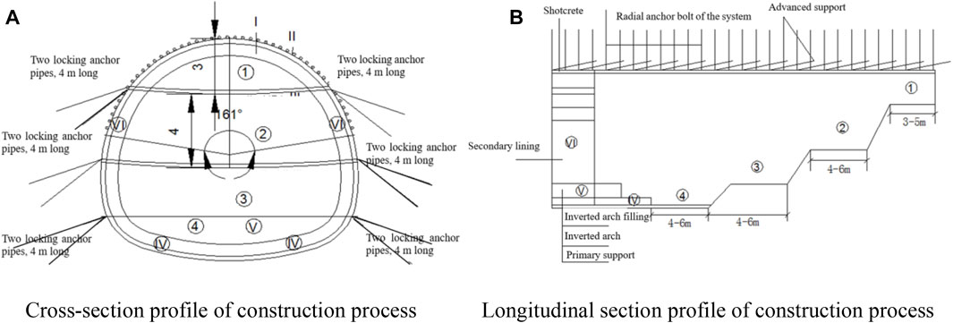
FIGURE 2. Construction process drawing. (A) Cross-section profile of the construction process. (B) Longitudinal section profile of the construction process.
4 Ansys finite element numerical simulation
4.1 Establishment of a 3D numerical model
This article built a model of the new Huilongwan Railway Tunnel undercrossing the existing Longzhouwan Highway Tunnel with Ansys, finite element analysis software, to study how the new railway tunnel excavation impacts the stability of the existing highway tunnel. When established, the model was 140 m long in longitude (Z direction) and 120 m wide (X direction), while the top reached the ground and bottomed out at 50 m beneath the inverted arch of Huilongwan Railway Tunnel. The region served as the calculation scope. Beam element Beam188 was used in wall rock, wall rock reinforcement area, primary support and secondary lining of the Longzhouwan Highway Tunnel, primary support and secondary lining of the Huilongwan Railway Tunnel, temporary steel frame inverted arch, inverted arch filling, advanced pipe shed, and finite element model pipe shed. Hexahedral solid element Solid45 was used in wall rock, wall rock reinforcement area, primary support and secondary lining of tunnels, temporary steel frame inverted arch and inverted arch filling. The whole model was divided into about 310,000 solid elements in total. According to the actual forces, the horizontal normal constraint was applied to the front, back, left, and right sides of the model; the bottom surface received three directional normal constraints; and the upper surface force was free with no constraints on it. The initial vertical crustal stress should be the deadweight of the rock-soil body. The computational model is shown in Figure 3.
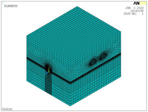
FIGURE 3. Model grid diagram.
4.2 Selection of model parameters
The parameters of tunnel support concrete were extracted from the physical and mechanical parameters of Level Ⅳ wall rock specified in the Code for Design of Railway Tunnel (Industrial Standard of the People’s Republic of China, 2016). C25 concrete and I20b I-steel constituted the primary support of Huilongwan Railway Tunnel, which was converted to a laminated composite medium to simplify the model. Instead of constructing the anchor bolt, the cohesive force and internal friction angle of wall rock were increased by 30%, equivalent to the grouting reinforcement effect. The physical and mechanical parameters of tunnel support concrete are shown in Table 1.
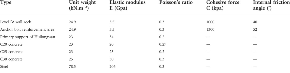
TABLE 1. Physical and mechanical parameters of the tunnel support concrete.
4.3 Simulation of the construction process
This article focuses on analyzing how new railway tunnel excavation influences the stability of the existing highway tunnel. Thus, the construction process of the existing highway tunnel was not considered. The initial state is the condition before the new railway tunnel construction by recovering the simultaneous displacement after the initial balance of the deadweight and the existing highway tunnel excavation. The new railway tunnel’s secondary lining construction lagged behind the tunnel surface, so it was not considered in this calculation. Excluding the deadweight and the existing highway tunnel excavation from the calculation, the excavation involved a total of 58 steps. The simulated excavation process includes:
(1) Construct the pipe shed before the excavation. In the simulation model, the shed was built with beam elements. Meanwhile, we modified the wall rock parameters for the construction of the wall rock reinforcement area and improved the cohesive force and internal friction angle of wall rock by 30% to have the equivalent effect as the grouting reinforcement.
(2) Kill the solid elements of the upper bench. Activate the solid elements for upper bench primary support after the calculation but before the computation. The exclusion of vertical support was the worst-case scenario.
(3) Kill the solid elements of the middle bench after lagging the upper bench. After calculation, activate the solid elements for middle bench primary support and the solid element for the temporary inverted arch for another round of computation.
(4) Kill the solid elements for the lower bench after lagging the middle bench. After calculation, activate the solid elements for lower bench primary support for another computation.
(5) Kill the solid elements for the inverted arch after lagging the lower bench. After calculation, activate the shell elements for inverted arch bench primary support for computation.
(6) After lagging the inverted arch excavation, kill the solid elements for a temporary inverted arch, and then activate the solid elements for inverted arch filling for computation.
4.4 Layout of monitoring sites
The DK23 + 480∼DK23 + 580 section of the Huilongwan Railway Tunnel undercrosses the Longzhouwan No.2 Highway Tunnel. Layout sites were set within 50 m on the left and right sides of the center line of the Huilongwan Railway Tunnel, and every 5 m there was a ring of monitoring sites on the formed lining of the Longzhouwan Highway Tunnel. This article fine-tuned the monitoring sites during numerical simulation to make them roughly consistent with on-site monitoring sites. Displacement data were extracted every 25 m.
The longitudinal layout diagram of monitoring sites of the existing highway tunnel is shown in Figure 4A.
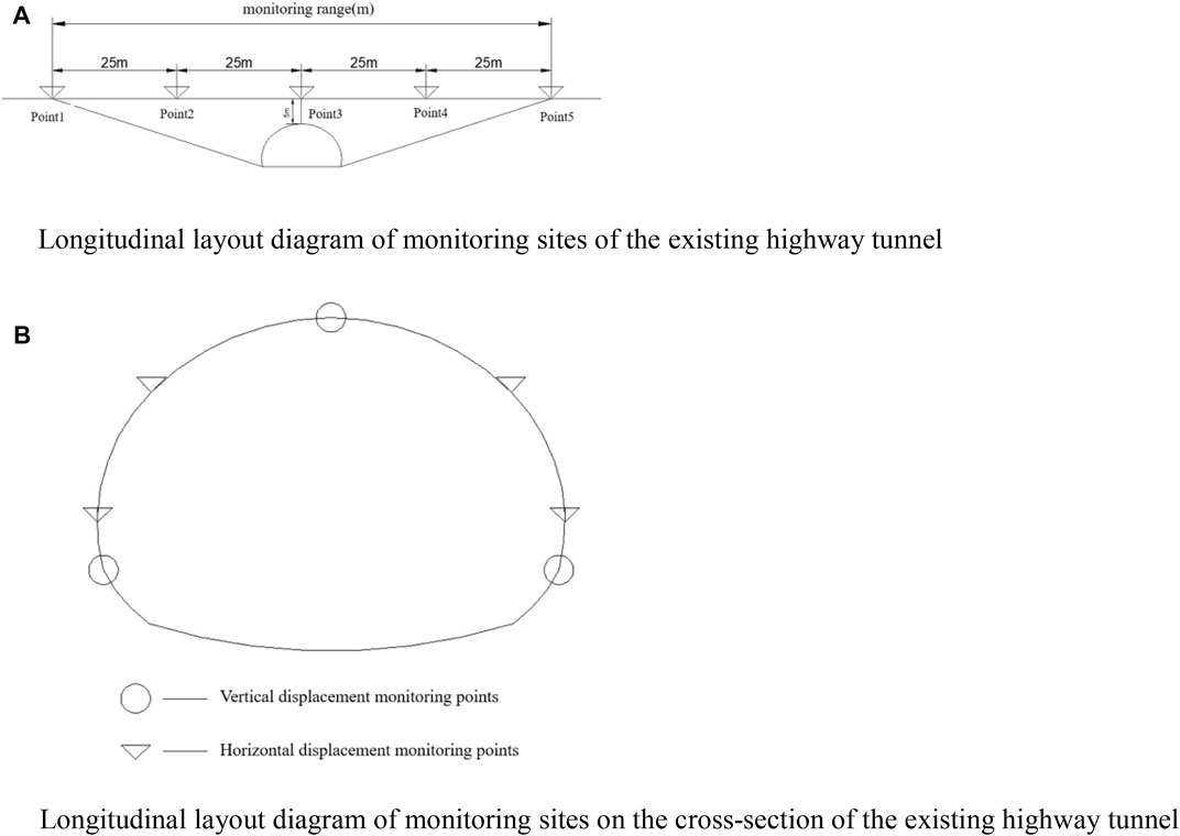
FIGURE 4. Layout of tunnel monitoring points. (A) Longitudinal layout diagram of monitoring sites of the existing highway tunnel. (B) Longitudinal layout diagram of monitoring sites on the cross-section of the existing highway tunnel.
In the entire new railway tunnel excavation, the construction progress monitors the vertical displacement of the vault in the left and right highway tunnels and both sides of the road, and the horizontal displacement of the spandrel of the left and right highway tunnels and both sides of the side wall. There were seven monitoring sites on each cross-section to supervise and analyze the displacement of the existing highway tunnel.
The longitudinal layout diagram of monitoring sites on the cross-section of the existing highway tunnel is shown in Figure 4B.
4.4 Analysis of displacement of the Longzhouwan Highway Tunnel
4.4.1 Analysis of vertical displacement of monitoring sites during the excavation
4.4.1.1 Analysis of vertical displacement of the left highway tunnel
Figure 5 show downward deformation occurred to the monitoring sites in the left highway tunnel, and the deformation gradually increased as the new railway tunnel excavation advances. When the excavation section of the new railway tunnel approached the bottom of monitoring sites in the left highway tunnel, the vertical displacement of the bottom of monitoring sites changed apparently and suddenly. When the excavation section was far away from the bottom of monitoring sites, the vertical displacement of monitoring sites increased on a small scale, linearly. Although the vertical displacement varies to different degrees and at various rates during the excavation, it follows similar changing patterns. However, when the excavation section of the new railway tunnel passed through the right highway tunnel, the vertical displacement of the left highway tunnel experienced a little impact. At the same time, it is found in the figure that the left and right inverted arches have relatively large deformations. The analysis shows that the main reason is that after the construction of the Underpass tunnel, the stress release deformation of the excavation arch crown of the new railway tunnel causes the synchronous deformation of the inverted arch bottom of the upper highway tunnel, resulting in a large deformation of the inverted arch, which reaches 2.11mm, and the deformation meets the requirements of tunnel deformation control.
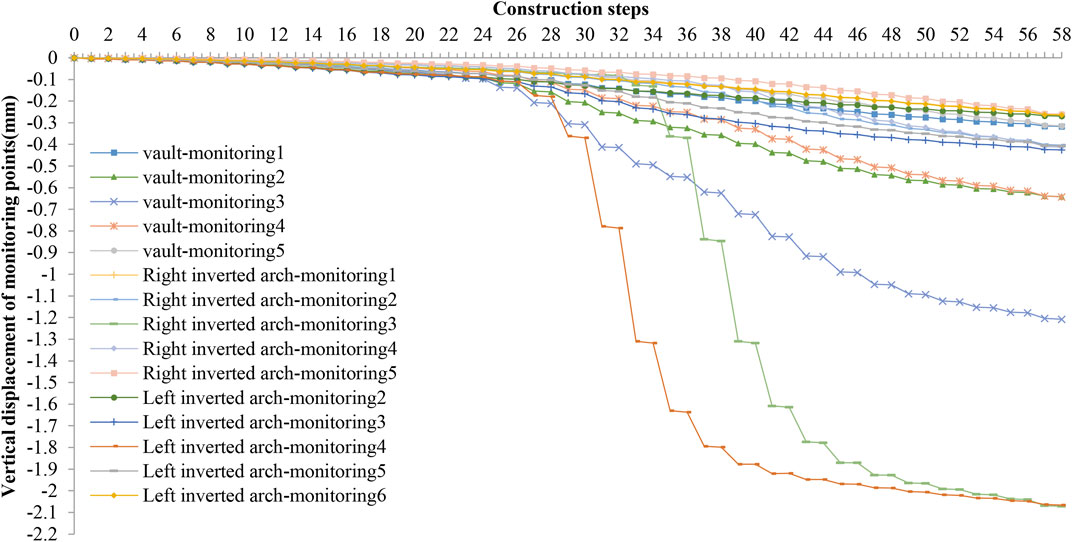
FIGURE 5. Vertical displacement of monitoring points of the left tunnel.
4.4.1.2 Analysis of vertical displacement of the right highway tunnel
Figure 6 shows that the deformation of monitoring sites in the right highway tunnel has similar changing patterns to those in the left highway tunnel in terms of size, rate, and regularity. The occurrence time and position of the sudden vertical displacement of monitoring sites were different. When the excavation section of the new railway tunnel approaches the bottom of monitoring sites in the right highway tunnel, there could be sudden vertical displacement. When the excavation section was far away from the bottom of monitoring sites in the right highway tunnel, the right highway tunnel experienced a small impact on the vertical displacement.
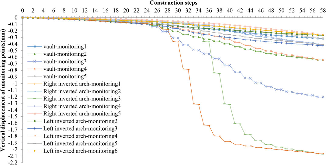
FIGURE 6. Vertical displacement of monitoring points of the right tunnel.
As the excavation of the new railway tunnel advanced, the vertical displacement of monitoring sites in the left and right highway tunnels was growing. For further analysis on the vertical displacement of monitoring sites in the left and right highway tunnels, especially when the vertical displacement reached its maximum, we selected such sites on different sections along the monitoring lines in the left and right highway tunnels after the new railway tunnel had been excavated through. The results are shown in Figure 7.
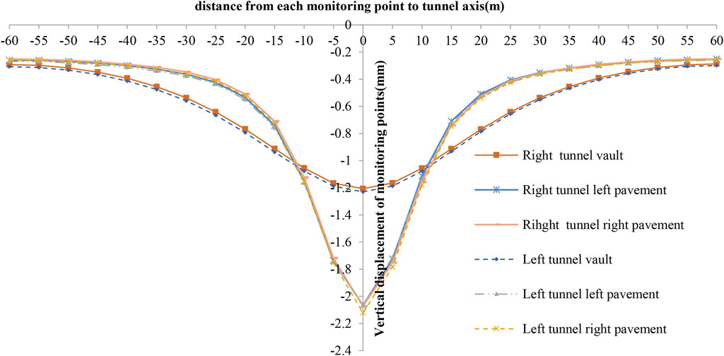
FIGURE 7. Vertical displacement through the rear tunnel monitoring line.
As shown in the aforementioned figures, the vertical displacement monitored by the sites on each section in the left and right highway tunnels differed in scale and rate at the same excavation stage, but the changing pattern was almost the same. At the same excavation stage, the vertical displacement of monitoring sites enlarged as the monitoring sites approached the center line of the new railway tunnel, while the vertical displacement narrowed as the monitoring sites moved farther away from the center line of the new railway tunnel. As a result, if the existing highway tunnel was approximately equal to the cross section of the new railway tunnel, the new railway tunnel excavation would dramatically impact the displacement of the existing highway tunnel.
We extracted the maximum vertical displacement of the left and right highway tunnels, as shown in Table 2. The maximum vertical displacement of the left and right highway tunnels, about 2.12 mm, occurred on the right side of the road section closest to the new railway tunnel.
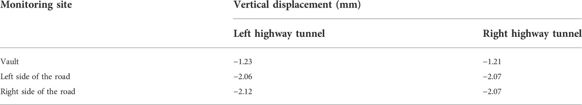
TABLE 2. Maximum vertical displacement of monitoring sites.
The aforementioned analysis showed that the stability of the existing highway tunnel section was under the influence of the new railway tunnel when the excavation of the latter one passed through it. However, the vertical displacement change of the left and right highway tunnels barely impacted each other. When the new railway tunnel was excavated 50 m away from the existing highway tunnel, the vertical displacement curve of monitoring sites on each monitoring line of the existing highway tunnel gradually flattened and converged to the corresponding values. The existing highway tunnel gradually stabilized as the subsequent excavation of the new railway tunnel had a smaller impact on the existing highway tunnel’s displacement.
4.4.2 Analysis of the horizontal displacement of monitoring sites during the excavation
4.4.2.1 Analysis of the horizontal displacement of the left highway tunnel
Figure 8 shows the horizontal displacement change curves of monitoring sites on each monitoring line of the left highway tunnel during the new railway tunnel excavation. In the figures, the horizontal displacement of monitoring sites grew larger as the monitoring sites approached the center line of the new railway tunnel. When the monitoring sites moved far away from the center line of the new railway tunnel, the horizontal displacement of monitoring sites narrowed. The horizontal displacement of monitoring sites fluctuated towards the negative direction before the excavation section of the new railway tunnel headed near the monitoring sites of the left highway tunnel. When the excavation section of the new railway tunnel was close to the monitoring sites of the left highway tunnel, the horizontal displacement of monitoring sites gradually increased. When the excavation section of the new railway tunnel was far away from the monitoring sites of the left highway tunnel, the curve reflecting the horizontal displacement of monitoring sites gradually dropped and finally flattened. Accordingly, any disturbance in the soil layer 50 m around the monitoring sites on the left highway tunnel may affect the horizontal displacement.
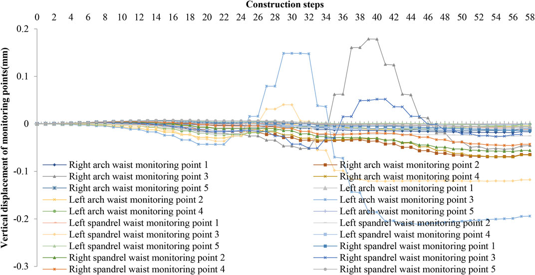
FIGURE 8. Horizontal displacement of the left tunnel monitoring point.
4.4.2.2 Analysis of horizontal displacement of the right highway tunnel
Figure 9 demonstrates the horizontal displacement change curves of monitoring sites on each monitoring line of the right highway tunnel during the new railway tunnel excavation. The curve trend was similar to that of the left highway tunnel. However, the difference was apparent. The horizontal displacement of monitoring sites of the right highway tunnel reached its maximum level when the excavation section of the new railway tunnel approached the bottom of monitoring sites of the right highway tunnel. Any disturbance in the 50 m soil layer might significantly affect the horizontal displacement of monitoring sites of the right highway tunnel.

FIGURE 9. Horizontal displacement of the right tunnel monitoring point.
Monitoring sites of the left and right highway tunnels detected the maximum horizontal displacement when the new railway tunnel was near. The vertical distance between the side wall and the new railway tunnel was shorter than that between the spandrel and the new railway tunnel, so the horizontal displacement of the side wall varied more substantially than that of the spandrel.
Guided by the designated excavation direction, the excavation section first passed the left monitoring sites on the spandrel and the side wall, and then passed the right monitoring sites on these parts. As a result, the left and right monitoring sites experienced large displacements at different excavation time spots. The relative displacement of each part grew steadily when the distance between the excavation section of the new railway tunnel and the bottom of monitoring sites of the existing highway tunnel was short, and the relative displacement narrowed and finally converged to be stable when the distance grew longer.
The horizontal displacement of monitoring sites in the left and right highway tunnels changed evidently when the excavation section of the new railway tunnel approached the bottom of monitoring sites of the existing highway tunnel. The excavation section impacted the deformation of the existing highway tunnel when it was passing through the bottom of the existing highway tunnel. Moreover, as the distance between the existing highway tunnel and the cross section of the new railway tunnel got closer, the new railway tunnel excavation had a larger impact on the horizontal displacement of the existing highway tunnel. Accordingly, the excavation would inevitably disturb the soil body of the existing highway tunnel when approaching the existing highway tunnel, thus leading to a rising soil loss rate. The stress redistribution of the soil body deformed the lining of the existing highway tunnel.
5 On-site monitoring
The K10 + 770 section of the Longzhouwan Highway Tunnel interchanged with the center line of the Huilongwan Railway Tunnel. A monitoring grid was set every 5 m along the K10 + 723∼K10 + 823 section. The monitoring sites are shown in Figures 6, 7. The analysis sampled vault settlement and surrounding convergence data from sections at 25 m intervals along the left highway tunnel over the months of the construction period.
5.1 Analysis of displacement of monitoring sites during the construction
As shown in Figures 10, 11, when the excavation section of the new railway tunnel approached the existing highway tunnel, both the settlement and surrounding convergence of each monitoring site increased steadily. Due to tunnel excavation and measurement error, the actual section with the maximum displacement was not different from the numerical simulation analysis. However, the data trend chart showed that the settlement curve and the surrounding convergence curve of monitoring sites on different sections of the monitoring lines of the left highway tunnel became gentle when the excavation of the new railway tunnel was far away from the left highway tunnel. The maximum settlement was about 2.2 mm, appearing at the vault of the ZK10 + 748 section. The maximum surrounding convergence was about 1.6 mm, appearing in the ZK10 + 723 section. After the Longzhouwan Highway Tunnel completed construction, the excavation of the new railway tunnel would cause changes to the displacement in a small and acceptable standard value range.
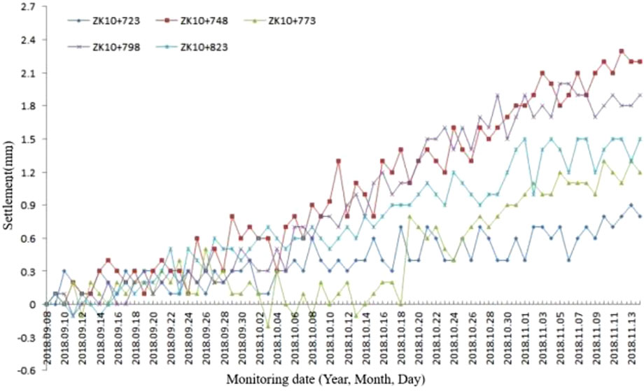
FIGURE 10. Settlement of each cross section of the on-site vault.
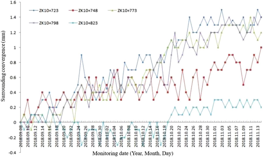
FIGURE 11. Surrounding convergence of monitoring sites on the on-site side wall.
6 Conclusion and suggestion
This article took the section of the new Huilongwan Railway Tunnel undercrossing the existing Longzhouwan Highway Tunnel, one of the East Ring Line Projects of Chongqing Railway Terminal, as the object of study. We simulated the displacement changes and structural deformation patterns of the existing highway tunnel caused by the new railway tunnel excavation with finite element analysis software and compared them with on-site measurements one by one to clarify the impact of the new railway tunnel excavation on the existing highway tunnel’s stability. The results are supported by the analysis of the displacement of different sections at the same excavation stage and the displacement of the same section at different excavation stages. The article draws the following conclusions:
(1) In the theoretical state, when the excavation section of the new railway tunnel approaches the bottom of the existing highway tunnel, the existing highway tunnel might experience large displacement. When the excavation section of the new railway tunnel passed the bottom of the monitoring sites in the existing highway tunnel, the existing highway tunnel’s stability was under great impact, resulting in a maximum vertical displacement of about 2.12 mm and a maximum horizontal displacement of about 0.25 mm. When the new railway tunnel was excavated after the new railway tunnel support was built and the tunnel surface moved far away from the axis of the existing highway tunnel, the existing highway tunnel stabilized with a settlement of about 2.12 mm and a horizontal displacement of about 0.21 mm. Subsequent excavation of the new railway tunnel would have a minor impact on the existing highway tunnel’s displacement when the excavation section is moved 50 m away from the existing highway tunnel.
(2) In practical engineering construction, the displacement fluctuated over the excavation process of the new railway tunnel due to systematic errors in monitoring. When the excavation section of the new railway tunnel approached the existing highway tunnel, both the settlement and the surrounding convergence of each monitoring point constantly increased. When the excavation section of the new railway tunnel advanced far away from the existing highway tunnel, the displacement gradually stabilized, and the impact of the new railway tunnel excavation on the stability of the existing highway tunnel steadily decreased. The maximum settlement of the existing highway tunnel reached about 2.2 mm, and the maximum surrounding convergence was about 1.6 mm. The results indicated that the actual situation was consistent with the finite element numerical simulation analysis results as the excavation of the new railway tunnel had considerably impacted the vertical displacement of the existing highway tunnel.
(3) Through the analysis of the combination of numerical simulation and field monitoring data, the maximum settlement of the existing tunnel is different. The maximum settlement of the simulation analysis is located in the inverted arch, while the maximum settlement of the monitoring is located in the arch crown of the existing tunnel, but the value is basically the same, about 2.1 mm. The analysis shows that the simulation analysis can basically reflect the construction situation and provide a research basis for the analysis.
(4) The displacement change curves from numerical simulation analysis and on-site monitoring showed similar variation patterns, despite small differences due to various reasons. The numerical simulation excluded the impact of rock vibration and pore water pressure caused by the mechanical excavation on the rock-soil body stability of the existing tunnels. In the actual engineering monitoring, the data fluctuations due to mechanical and human errors during the measurement would lead to a larger displacement from on-site monitoring than that from numerical simulation analysis. However, the difference was acceptable.
(5) Upon completing the Longzhouwan Highway Tunnel, excavating the Huilongwan Railway Tunnel would certainly impact the existing highway tunnel. Reinforcing the support of the new railway tunnel would not affect the existing highway tunnel. The maximum settlement of the existing highway tunnel was about 2.2 mm, while the maximum surrounding convergence was about 1.6 mm. Both fell within the controllable range. The new railway tunnel excavation would cause the displacement of the existing highway tunnel change but in a small and acceptable standard after displacement convergence. The excavation and support of the new railway tunnel were reasonable and had a small impact on the stability of the existing highway tunnel.
(6) The railway tunnel Undercrossing Longzhouwan tunnel adopts the large angle oblique crossing scheme, which has a large construction range. The analysis of on-site monitoring and numerical simulation deformation data shows that the main deformation stage is the excavation process of the upper steps of the Undercrossing tunnel, and the initial support is not completed. Therefore, during the construction period, it is necessary to optimize the construction scheme to reduce the open hole time and complete the tunnel support on time.
(7) The comparative analysis proved that the non-blasting excavation of the three-step temporary invert method was reliable in construction. Specifically, the method could ensure the safety of the existing highway tunnel by controlling the deformation of the existing highway tunnel within a reasonable range.
Data availability statement
The original contributions presented in the study are included in the article/supplementary material; further inquiries can be directed to the corresponding author.
Author contributions
QZ: writing—original draft, conception, data analysis, and data collection; YD: review of the manuscript. All authors have approved the manuscript and agreed with its submission to the journal.
Acknowledgments
The authors are grateful to all authors and editors.
Conflict of interest
QZ is employed by The Third Engineering Co., Ltd. of China Railway 20th Bureau Group.
The remaining author declares that the research was conducted in the absence of any commercial or financial relationships that could be construed as a potential conflict of interest.
Publisher’s note
All claims expressed in this article are solely those of the authors and do not necessarily represent those of their affiliated organizations, or those of the publisher, the editors, and the reviewers. Any product that may be evaluated in this article, or claim that may be made by its manufacturer, is not guaranteed or endorsed by the publisher.
References
Chen, W. Z., Zheng, D., and Yu, J. X. (2015). Impact of cross tunnel construction on existing tunnel stability. J. Rock Mech. Eng. doi:10.13722/j.cnki.jrme.2013.1809
Gui, Y. C. (2019). The impact of different proximity on the stability of existing tunnel. North. Transp. 313 (05), 84
Industrial standard of the People's Republic of China (2016). TB 10003-2016 Code for design of railway tunnel.
Leng, B., Qiu, W. G., and Gong, L. (2014). Extension analysis on the impact of newly built undercrossing tunnel on existing tunnel. J. Southwest Jiaot. Univ. 49 (04), 637. doi:10.3969/j.issn.0258-2724.2014.04.012
Li, L. P., Li, S. C., and Zhao, Y. (2012). Experimental study on 3d geomechanical model for the progressive failure process of soft and fractured surrounding rock in large cross-section tunnel. Chin. J. Rock Mech. Eng. 31 (3), 550. doi:10.3969/j.issn.1000-6915.2012.03.013
Li, S. C., Song, S. G., and Li, L. P. (2013). Development and application of fluid-solid coupling model test system for undersea tunnel. J. Rock Mech. Eng. 32 (5), 8. doi:10.3969/j.issn.1000-6915.2013.05.005
Liu, Z., Fang, M., Zhou, C. Y., and Shi, H. O. (2010). Study on the impact of the complex strata and spacing around new tunnel on the settlement of existing tunnel during the construction of cross tunnel. Chin. J. Eng. Geol. 18 (5), 736. doi:10.3969/j.issn.1004-9665.2010.05.021
Tian, Z. Y. (2006). Experimental study on similar model of small clear distance tunnel on highway. Chengdu, Sichuan: Southwest Jiaotong.
Keywords: new railway tunnel, existing highway tunnel, cross construction, stability, three-step temporary invert method
Citation: Zhu Q and Ding Y (2022) Impact of new undercrossing tunnel excavation on the stability of the existing tunnel. Front. Earth Sci. 10:915882. doi: 10.3389/feart.2022.915882
Received: 08 April 2022; Accepted: 30 June 2022;
Published: 22 July 2022.
Edited by:
Hans-Balder Havenith, University of Liège, BelgiumReviewed by:
Liang Cheng, China Merchants Chongqing Communications Technology Research & Design Institute Co., Ltd., ChinaFang Liu, China Railway Engineering Design and Consulting Group Co., Ltd., China
Copyright © 2022 Zhu and Ding. This is an open-access article distributed under the terms of the Creative Commons Attribution License (CC BY). The use, distribution or reproduction in other forums is permitted, provided the original author(s) and the copyright owner(s) are credited and that the original publication in this journal is cited, in accordance with accepted academic practice. No use, distribution or reproduction is permitted which does not comply with these terms.
*Correspondence: Yanping Ding, ZGluZ3lhbnBpbmcwNDVAMTYzLmNvbQ==