 Juyu Jiang
 Ye Lu
Ye Lu- College of Mines, Liaoning Technical University, Fuxin, China
Highwall mining with backfill technology will be one of the main techniques of raising the recovery rate of coal resources under the end-slope all over the world in the future, in which the coal pillar setting is the key to ensure the successful application of this technology, and the calculation of inelastic zone width of a coal pillar has important guiding significance for the coal pillar setting in highwall mining with backfill. However, at present, in order to accurately calculate the inelastic zone width of a coal pillar under the condition of highwall mining with backfill, a calculation model of the inelastic zone width of highwall mining with backfill independent of empirical parameters is established by using a limit equilibrium method, orthogonal experiment method, and non-linear fitting method. In order to verify the correctness and reliability of the model, this study takes the geological conditions of the Antaibao open-pit mine in Pingshuo, Shanxi Province, China, as the engineering background to verify the calculation accuracy of the model. The results show that the calculation model established in this study can accurately calculate the inelastic zone width of the coal pillar under highwall mining with backfill and can meet the engineering needs.
1 Introduction
According to statistics, in the past 40 years, about two-thirds of the world’s coal production came from open-pit mining (Matsui et al., 2004; Brent, 2011; Shimada et al., 2013; Dixit and Pradhan, 20142014; Kuznetsova and Anfyorov, 2019; Looney, 2021). However, in the process of open-pit mining, end-slope pressure coal occurs because of the change of coal seam inclination, the problem of mining boundary, the arrangement of the bucket truck production system required for open-pit mining, and the need of maintaining slope stability. It means that it will leave a large number of “stagnant” coal that requires special measures to mine under the end-slope at the end of mining (Matsui et al., 2001; Wang et al., 2019). If these “stagnant coals” are not mined, they will be buried again once the inner dumping is formed, eventually leading to a waste of resources (Chen et al., 2011; Chen et al., 2013). According to incomplete statistics, it is estimated that the amount of coal pressed by the end-slope in China has reached 20% of the mining reserves (Tao and Shuang-shuang, 2020), and more than 20 million tons of coal is pressed by the end-slope each year. In addition, the coal pressed by the end-slope will be buried at a rate greater than 300 m each year with the follow-up of the internal dumping, becoming a permanent “stagnant” resource (Shao-hui et al., 2014; Xiao-feng, 2015). Therefore, it is of great significance to carry out end-side mining, which not only brings huge economic benefits but also reduces potential safety hazards.
In the 1940s, the United States put forward the highwall mining technology to realize the mining of coal resources under the end-slope (Mo et al., 2016); by the 1970s, the technology was mature and formed the current highwall mining technology; by the 1980s, the technology was officially commercialized (Baotang, 2014). Highwall mining technology is a remote mining technology combined with open-pit and underground mining. It can realize the mining of coal resources under the end-slope without support by arranging continuous shearer or spiral shearer and other auxiliary production equipment under the end-slope and remotely controlling them (Porathur et al., 2014; Fan, 2015). Highwall mining technology has many advantages: short infrastructure time, low operating cost, relatively low labor cost, flexibility, easy operation, safety, and recovering small coal pieces. Therefore, major coal-producing countries such as Australia (Huang, 2015), India (Elmouttie and Karekal, 2017), Indonesia (Sasaoka et al., 2016), China (Wang and Zhang, 2019; Wang et al., 2021), and Thailand (Boeut, 2015) have successively introduced this technology from the United States and successfully applied it. At the same time, it has also become the primary method for countries to mine the coal resources pressed under the end-slope. In addition, it is reported that ADDCAR’s continuous shearer-type highwall mining system has liberated 120 million tons of coal resources pressed under the end-slope from 1990 to 2019. Australia that introduced the technology earlier has successfully liberated more than 21 million tons of coal (Hartcher and Case, 2019).
Since highwall mining is almost under the condition of no support to mine the coal resources under the end-slope, it is necessary to ensure the stability of the mining hole, end-slope, and slope. In order to ensure the stability of the mining hole, end-slope, and slope, coal pillars shall be set between mining holes to support the overlying strata to achieve the purpose of the mining hole, end-slope, and slope stability. Studies have shown that when the supporting coal pillar setting is unreasonable, it will induce a catastrophic failure of the supporting coal pillar and the “domino” type chain instability of the supporting coal pillar group, which eventually leads to the collapse of the mining hole, instability of the sidewall and the large-scale landslide of the slope, and destruction of the highwall production system, resulting in economic losses and casualties (Zipf and Mark, 2005; Li et al., 2020). So, whether the coal pillar setting is reasonable or not directly determines the success of highwall mining. Therefore, the problem of the coal pillar setting in highwall mining has always been a research hotspot of experts and scholars all over the world. Through the continuous efforts of experts and scholars in the world, fruitful results have been achieved on this issue. These results include the empirical formula obtained by mathematical statistics analysis and fitting, the theoretical model obtained by mechanical theory derivation and analysis, and the laws obtained by numerical simulation. For example, Salamon (1967) obtained the Salamon–Munro coal pillar strength formula with far-reaching influence for the following Australian coal pillar strength formula [CSIRO coal pillar strength formula (Duncan Fama et al., 2001)] and Indian coal pillar strength formula [CIMFR coal pillar strength formula (Verma et al., 2014)] through statistical analysis of the geometric shapes of 96 stable coal pillars and 27 failure coal pillars in South African coal mines and an in-depth study of the strength of rectangular coal pillars; Wang et al. (2019) applied Hoek–brown and Mohr–Coulomb failure criteria to establish a mechanical model of the failure width of a collinearly supported coal pillar in order to study the failure of the supporting coal pillar caused by large deformation in open-pit mining in China, through which the instability mechanism and failure process of the supported coal pillar in highwall mining was revealed; in order to study the influence of highwall mining sequence on the stability of the supporting coal pillar, Huang (2015) studied it by using the FLAC3D numerical simulation method. The results show that different mining sequence has a significant influence on the stability of the high slope. Skip mining can achieve better mining hole stability and a smaller coal pillar plastic area compared with sequential mining.
However, although the research on the stability of coal pillars in highwall mining has been conducted for decades and has achieved fruitful results, the research on the stability of coal pillars under the condition of highwall mining with backfill is scarce. The possible reason for this situation is that there is no highwall mining working face with backfill in the world at present. However, through numerical simulation research, experts and scholars around the world have shown that the highwall mining with backfill will further improve the supporting coal pillar stability and liberate more coal resources pressed under the end-slope while further reducing the size of the coal pillar set (Porathur et al., 2017). For example, Lier (2014) used numerical simulation to evaluate the feasibility of highwall mining with backfill in the West Bokaro mine in Jharkhand, India. Through numerical simulation, it was found that highwall mining with backfill can theoretically recover 36% more coal resources than traditional highwall mining methods; Mo et al. (2018) used numerical simulation to study the influence of backfill on the stability of coal pillars in highwall mining. Through the study, it was found that the performance of the coal pillar would change with the properties and backfill amount of backfill body and the high recovery rate of coal resources under the coal pillar with reasonable size can be realized under reasonable backfill strategy; Matsui et al. (2000) (2018) also found that implementing highwall mining with backfill can improve the stability of coal pillars, improve the recovery rate of coal resources, and avoid the occurrence of surface subsidence through a numerical simulation. However, a numerical simulation is based on some theories or assumptions, which is not real reality. If there are problems in the theoretical model itself or assumptions, as well as the calculation accuracy, it will affect the accuracy of the simulation results.
From the research of the aforementioned experts and scholars, it is not difficult to find that the coal pillar set is vital for highwall mining, supporting coal pillar stability of highwall mining, end-slope stability, and slope stability. The highwall mining with backfill can reduce the size of the coal pillar set, and further improve the stability of the supporting coal pillar and liberate more coal resources under the end-slope. Nevertheless, up to now, there are few reports on using mechanical theory to study the influence of highwall mining with backfill on coal pillars. However, the theoretical model derived based on the mechanics theory has better applicability and generalization than the numerical simulation. In the study of the coal pillar setting, if the inelastic zone width can be calculated, it can be a good guide for the coal pillar setting and provide a numerical guarantee for the coal pillar setting. Therefore, this study uses the limit equilibrium method to construct the theoretical models of coal pillars under the conditions of incomplete filling and complete filling, respectively, and calculates the inelastic zone width of a coal pillar in highwall mining with backfill to provide numerical guarantee and ideas for the coal pillar setting in highwall mining with backfill.
Through the comparison between numerical simulation and engineering examples, the mechanical derivation results are verified, and the influence of filling body on the stability of the coal pillar in end-slope mining is studied to ensure the accuracy of the derivation results.
2 The Full Stress and Strain Process of Coal
Many experts and scholars in the world have shown that the failure of rock mass is a complex progressive failure process through theoretical analysis (Ti, 2021; Xu et al., 2021), laboratory experiments (Yumlu and Ozbay, 1995; Tiwari and Rao, 2006; Zhang et al., 2022), and outdoor experiments (Zhang et al., 2021). Furthermore, it will generally experience three deformation stages: elastic deformation stage, plastic-softening deformation stage, and plastic-flow deformation stage, as shown in Figure 1. Coal is also a particular rock, which exists underground and belongs to a part of the rock mass. Therefore, its failure will also experience the elastic deformation stage, plastic-softening deformation stage, and plastic-flow deformation stage. Medhurst and Brown (1998) carried out triaxial compression experiments on coal samples with different diameters and obtained the whole stress and strain curve. It can be seen that the failure of coal and rock also experienced the aforementioned three stages. These three stages will be reflected in the underground coal and rock mass in three zones: elastic zone, plastic-softening zone, and plastic-flow zone, in which the plastic-softening zone and plastic-flow zone are called inelastic zones. However, the inelastic zone is the danger zone in the critical failure state or already in the failure state. So, it is necessary to pay attention to the inelastic zone of the coal pillar, and for which this study also takes the calculation for the inelastic zone width as the research content.
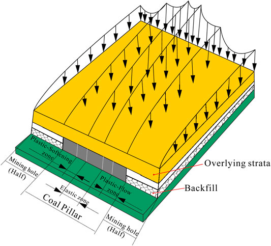
FIGURE 1. Models of the elastic zone, plastic-softening zone, and plastic-flow zone of the coal pillar.
3 Mechanics Model Based on the Limit Equilibrium Method
Through the study, we found that the strength of the coal pillar will change with the change of filling properties and filling amount. According to the Mohr–Coulomb criterion, the stress on the coal pillar is analyzed. It is assumed that before filling, the coal pillar is mainly subjected to the vertical stress generated by the self-weight of overlying strata and the corresponding lateral stress. By constructing the mechanical model of the coal pillar in highwall mining under different filling conditions, the effect of filling body on the coal pillar is analyzed.
3.1 Establishment of the Mechanical Model
According to the full stress and strain curve of coal obtained from the progressive failure process of rock mass studied by experts and scholars at home and abroad through a theoretical analysis and indoor and outdoor experiments, the stress at the upper interface of the coal pillar generally reaches a maximum peak (kγH) at the interface between the elastic zone and the plastic-softening zone. At the same time, the stress value (γH) at the interface between the plastic-softening and plastic-flow zones is almost equal to the upper interface load. Filling mining is used because filling the backfill will provide lateral stress for the supporting coal pillar. The coal pillar will change from a biaxial stress state to a triaxial stress state, thereby inhibiting the expansion of the plastic zone of the coal pillar (Wang et al., 2011). Therefore, the backfill mainly provides lateral stress (Px) to improve the stability of the coal pillar. Under the condition of incomplete filling, the coal pillar will expand and deform toward the mining hole under the action of overburden load. Since the mining hole has been filled, the expansion deformation will squeeze the backfill and make the backfill concave inward. It can be considered that the lateral stress provided by the backfill to the coal pillar at this time is the passive Earth pressure generated by the interaction between the backfill and the coal pillar. At the same time, due to incomplete filling, the upper interface of the filling body is not constrained, so the upper interface of the backfill will also expand and deform and move upward, resulting in downward friction force (Ty) at the interface between the backfill and the coal pillar. Under the condition of complete filling, the backfill will cause downward depression compression in the longitudinal direction under the action of overburden load. Under this compression, the expansion deformation occurs in the horizontal direction simultaneously, thereby squeezing the coal pillar so that the coal pillar has the trend of depression compression inward and then inhibiting the expansion of the inelastic zone of the coal pillar. Therefore, it can be considered that the lateral stress provided by the backfill to the coal pillar is the active Earth pressure generated by the interaction between the backfill and the coal pillar. Due to the downward depression compression in the longitudinal direction, the backfill has downward movement, resulting in upward friction force (Ty1) at the interface between the backfill and the coal pillar. Based on these, the mechanical models are established as shown in schematic diagrams 2–3.
3.2 Calculation Model for the Inelastic Zone Width of Highwall Mining With Backfill Under the Incomplete Filling Condition
Because the principle of the limit equilibrium method is simple and has been very mature in the research and application of geotechnical engineering, the limit equilibrium method is used to calculate and study the inelastic zone width of the highwall mining with backfill under incomplete filling conditions. The research in the previous section shows that the coal pillar will form the elastic zone, plastic-softening zone, and plastic-flow zone under the action of overlying load. The plastic-softening zone and plastic-flow zone are collectively referred to as the inelastic zone. In order to simplify the research process, the plastic-flow zone and the plastic-softening zone are respectively taken as the separator for calculation and research and set the ABCD and ADEF in Figure 2 as the plastic-flow zone and the plastic-softening zone, respectively. Their widths are x0 and x1, respectively. Finally, the calculation models for the inelastic zone width of highwall mining with backfill under incomplete filling conditions are established, as shown in Figure 4.
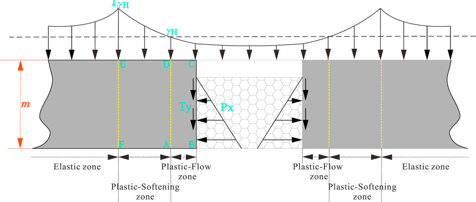
FIGURE 2. Schematic diagram of the mechanical model without roof connection (single-side gob model).
3.2.1 Calculation for Plastic-Flow Zone Width
Without considering the volume force, the interface stress in the limit equilibrium zone satisfies (Chen et al., 2020)
From Eq. 1, we can get
According to Eq. 2, it can be set as follows:
Substituting Eq. 3 into Eq. 2, we can get
After finishing, we can get
Since the left and right sides of Eq. 5 are functions about x and y, respectively, it can be set as follows:
By solving the differential equations of Eq. 6, we can get
Substituting Eq. 7 into Eq. 3 and Eq. 1, we can get
Because the upper boundary of the coal seam is y = (ϖ-1) m, it can be set as follows:
Then the upper boundary stress of the coal seam can be obtained according to Eq. 9 and Eq. 8, as follows:
According to the mechanical model in Figure 2, the plastic-flow zone ABCD in the whole limit equilibrium zone is taken as the separator to obtain the model, as shown in Figure 4. Since the resultant force in the x-direction and the y-direction are both 0, we can get
As can be seen from Eq. 11, Eq. 11 is an equilibrium equation about x0, which can be derived from x0:
i.e.,
Solving Eq. 11, we can get
Let x = x0 in Eq. 10 and compare it with Eq. 13, then we can get
According to the assumption [σy]x=x0 and Eqs 11–14, we can get
Since
Eq. 16 becomes
According to Eq. 16 and Eq. 18, we can get
Substituting Eq. 19 into Eq. 16, the plastic-flow zone width of the single side goaf in highwall mining with backfill under the incomplete filling condition can be obtained as follows:
where A is lateral stress coefficient; m is the mining hole height, m; γ is the average volume force of overburden, N/m3; H is the overlying rock mass height, m; φ0 is the internal friction angle of coal, °; C0 is the cohesion of coal, Pa; Px is the passive Earth pressure, Pa, Px=0.5γbackfill (ϖm)2k12+2ϖmck1; γbackfill is the bulk density of backfill, N/m3; c is the cohesion of backfill, Pa; k1 is the passive Earth pressure coefficient, k1=tan(45°+φ/2); φ is the internal friction angle of backfill, °; and ϖ is the filling rate.
3.2.2 Calculation for Plastic-Softening Zone Width
According to the aforementioned Eqs 1–10, set and solve the equations in the same way, and combined with the mechanical model in Figure 3, take the plastic-softening zone ADEF in the whole limit equilibrium zone as the separator to obtain the model shown in Figure 4. From the natural balance in the y-direction, the resultant force in the x-direction is 0, and we can get
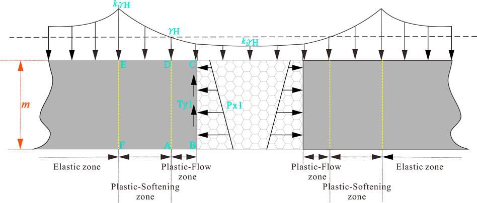
FIGURE 3. Schematic diagram of the mechanical model during roof connection (single-side goaf model).
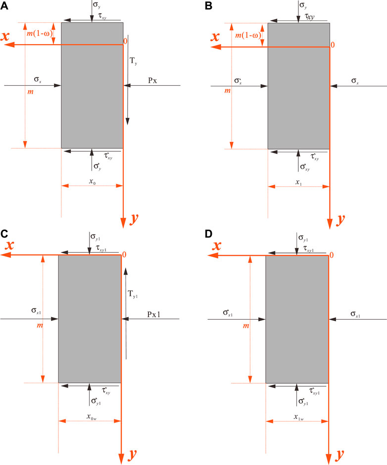
FIGURE 4. Calculation model for highwall mining with backfill under the filling condition (single-side goaf model). (A) Calculation model for plastic-flow zone in highwall mining with backfill under the incomplete filling condition. (B) Calculation model for plastic-softening zone in highwall mining with backfill under the incomplete filling condition. (C) Calculation model for plastic-flow zone of highwall mining with backfill under the complete filling condition. (D) Calculation model for plastic-softening zone of highwall mining with backfill under the complete filling condition.
Similarly, it is known from Eq. 23 that this is a balance equation about x1 so that it can be derived from x1 and solve the differential equation, and the following can be obtained:
Let x = x1 in Eq. 21 and compare it with Eq. 24, we can get
According to the assumptions [σy1]x=x1 = kγH and [σy1]x=x0 = γH and Eqs 21–25, we can get
Since
Eq. 26 becomes
According to Eq. 28 and Eq. 26, we can get
Substituting Eq. 29 into Eq. 25, the plastic-softening zone width of the single side goaf in highwall mining with backfill under the incomplete filling condition can be obtained as follows:
where A is the lateral stress coefficient; m is the mining hole height, m; γ is the average volume force of overburden, N/m3; H is the overlying rock mass height, m; φ0 is the internal friction angle of coal, °; C0 is the cohesion of coal, Pa; and k is the vertical stress concentration factor.
In summary, the inelastic zone width of the single side goaf in highwall mining with backfill under the incomplete filling condition can be obtained as follows:
When both sides are mined out, there will be stress superposition. Therefore, under the condition of incomplete filling, the inelastic zone width xs of the bilateral side goaf in highwall mining with backfill is twice that of the single side goaf, i.e.,
3.3 Calculation Model for the Inelastic Zone Width of Highwall Mining With Backfill Under the Complete Filling Condition
The formula for the inelastic width of the highwall mining with backfill under the complete filling condition is derived according to the same derivation process as the previous section. In order to reduce unnecessary repetition, the calculation formulas for plastic-flow zone width x0w and plastic-softening zone x1w are derived by taking the plastic-flow zone ABCD and the plastic-softening zone ADEF (as shown in Figure 4) in the whole limit equilibrium zone in Figure 3 as separators. The formulas obtained by derivation are shown in Eq. 33 and Eq. 34:
where A is the lateral stress coefficient; m is the mining hole height, m; γ the is average volume force of overburden, N/m3; H is the overlying rock mass height, m; φ0 is the internal friction angle of coal, °; C0 is the cohesion of coal, Pa; Px1 is the active Earth pressure, Pa, Px1=(0.5γbackfillm2+qm)k23-2mck3; γbackfill is the bulk density of backfill, N/m3; c is the cohesion of backfill, Pa; k3 is the active Earth pressure coefficient, k3=tan(45°-φ/2); φ is the internal friction angle of backfill, °; q is the load acting on backfill, q=k2γH; and k2 is the stress coefficient.
where A is the lateral stress coefficient; m is the mining hole height, m; γ is the average volume force of overburden, N/m3; H is the overlying rock mass height, m; a is the height of backfill, m; φ0 is the internal friction angle of coal, °; C0 is the cohesion of coal, Pa; and k is the vertical stress concentration factor.
Finally, the inelastic zone width of highwall mining with backfill under complete filling condition is
Similarly, when both sides are mined out, there will be stress superposition. Therefore, under the condition of complete filling, the inelastic zone width xsw of the bilateral side goaf in highwall mining with backfill is twice that of the single side goaf, i.e.,:
3.4 Model Correlation Coefficient Fitting
Through the mechanical derivation of sections 3.1–3.3, the mechanical models of Eq. 20, Eq. 30, Eq. 33, and Eq. 34 are finally obtained. However, the lateral stress coefficient (A), vertical stress concentration coefficient (k), and stress coefficient (k2) in the models are uncertain, which brings some obstacles to the model use. Suppose these coefficients become parameters related to mining design, such as mining hole width (D), mining hole height (G), filling rate (C), and overburden height (H). In that case, the applicability of the model will be significantly improved. According to experience, A, k, and k2 will change with D, G, C, and H. Since the non-linear fitting method can study these relationships well, the non-linear fitting method is used to study the relationships between A, k, k2 and D, G, C, and H, respectively.
In order to comprehensively study the relationship between A, k, and k2, and D, G, C, and H with less experimental times, the orthogonal experimental method was adopted. Because the orthogonal experiment is based on the orthogonality from the comprehensive test to select some representative points with the “uniform dispersion, neat comparable” features for testing, it is a high efficiency, fast, and economical method for research multifactor multilevel experimental. Since A and k are related to D, G, C, and H, four factors affect A and k. In addition, it is hoped to obtain better experimental results with as few experiments as possible, so it is decided to set the experiment level to 4 (the level set as shown in Table 1), i.e., it is an orthogonal experiment with four factors and four levels. However, fitting k2 is only for calculating the Earth pressure Px with overlying load, but there is load above the backfill only when complete filling, so the filling rate must be 1. Similarly, to obtain better experimental results, set the experiment level to 4 (each level setting is shown in Table 2). Finally, the experiment of k2 is determined as an orthogonal experiment with three factors and four levels. After the number of influencing factors and experimental levels of the aforementioned experiments is determined, Minitab is used to generate the corresponding orthogonal experiment table automatically. The generated orthogonal experiment tables are shown in Table 3 and Table 4.
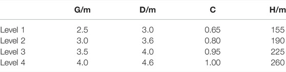
TABLE 1. Four levels for research A and k.
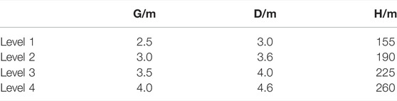
TABLE 2. Four levels for research k2.
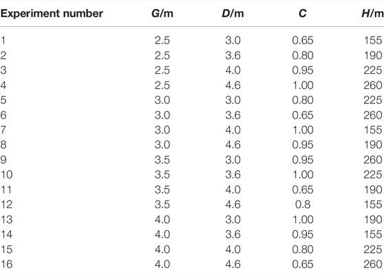
TABLE 3. Orthogonal experiment table for researching A and k L16(44).
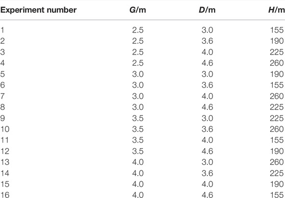
TABLE 4. Orthogonal experiment table for researching k2 L16(43).
However, the aforementioned experiments should be based on certain geological conditions, but this study is theoretical research. Therefore, to test the aforementioned experimental scheme quickly, effectively, and economically, the numerical simulation method is used. FLAC3D numerical simulation software is now widely used in civil engineering, geotechnical engineering, hydraulic engineering, geological engineering, and other fields. Therefore, FLAC3D numerical simulation software is used to simulate the experimental scheme in this study. In addition, also because this study is a theoretical research rather than a practical engineering application, the rock physical and mechanical parameters in the published studies can be used as the physical and mechanical parameters of the experimental research in this study. The study “Simulation Research for the Influence of Mining Sequence on Coal Pillar Stability under Highwall Mining Method” (Huang, 2015) studied the influence of mining sequence on coal pillar stability through numerical simulation. It belongs to the same field of highwall mining as this study. Therefore, some rock physical and mechanical parameters of the aforementioned study are used in this study. Moreover, the study “The influence of roadway backfill on the coal pillar strength by numerical investigation” (Wang et al., 2011) studied the influence of filling on coal pillar strength through numerical simulation. It involves the physical and mechanical parameters of the backfill. So, the physical and mechanical parameters of the backfill of the aforementioned study are used in this study. The physical and mechanical parameters of the numerical simulation model are shown in Table 5.
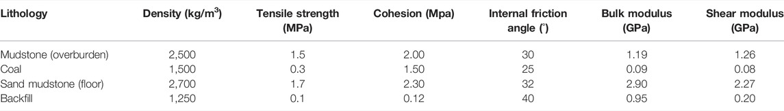
TABLE 5. Physical and mechanical parameters of the model in numerical simulation.
Since the calculation model studied in this study is mainly suitable for two-dimensional conditions, it is hoped that A and k at the elastic–plastic boundary of the upper interface in the coal seam and the k2 at the upper interface in the backfill can be obtained through experiments. However, these are obtained through the calculation of vertical stress and horizontal stress. Therefore, according to the experimental plans, this study establishes the pseudo two-dimensional models with a thickness of 1 m, a width of 100 m, and a mining hole spacing of 7 m. Furthermore, it arranges a measuring line with 501 measuring points for monitoring vertical stress and horizontal stress on the upper interface of the coal seam in the model. The distance between the measuring points is 0.2 m. After simulating, the vertical and horizontal stress at the elastic–plastic interface is extracted and calculated by Eq. 37 and Eq. 38 for calculating A and k. Similarly, extract the vertical stress at the upper interface of the backfill, and calculate the stress coefficient k2 with Eq. 37. After calculation and sorting, the experimental results of each group are shown in Table 6.
where k is the vertical stress concentration; A is the lateral horizontal stress coefficient; σzm is the vertical stress extracted from the model, Pa; σxm is the horizontal stress extracted from the model, Pa; γ is the average volume force of overburden, N/m3; and H is the buried depth of unit body, m.
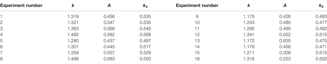
TABLE 6. Orthogonal experimental results of A, k, and k2.
After sorting out the aforementioned experimental data, fit the relationship between k and A and G, D, C, and H, respectively, and the relationship between k2 and G, D, and H. However, there is no prior model form before fitting these relations, so this study uses the “fast formula fitting search” function in the mathematical optimization software 1stOpt (Liu et al., 2020; Li et al., 2021a; Li et al., 2021b; Li et al., 2021c; Shen et al., 2021; Zhang et al., 2021) to fit the model. The relationship formula obtained by fitting is shown in Eqs 39–41, and the fitting curves are shown in Figure 5. RMSE, SSE, and R2 of fitting curves in each relationship formula show that RMSE and SSE are less than 0.05 and 0.03, respectively, and the R2 is greater than 0.87. Therefore (Li et al., 2021d; Kong et al., 2021; Shen et al., 2021; Kong et al., 2022; Niu et al., 2022), it can be explained that the fitted relationship formula has a high degree of fit with the experimental data and has a basis for use. Therefore, substituting Eqs 39–41 into Eq. 20, Eq. 30, Eq. 33, and Eq. 34 can obtain the final calculation model for the calculation of the inelastic zone width of the coal pillar in the highwall mining with backfill.
where G is the mining hole height, m; D is the mining hole width, m; C is the filling rate; and H is the overburden height, m.
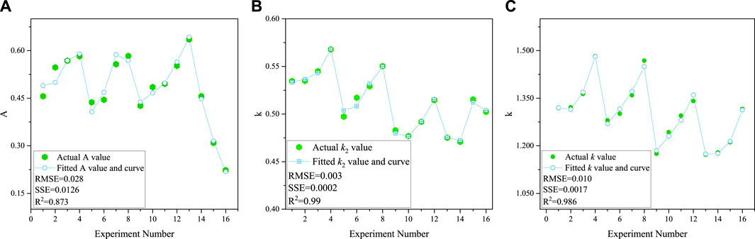
FIGURE 5. Fitting curves of A, k, and k2. (A) Fitting curve of A; (B) fitting curve of k2; and (C) fitting curve of k.
4 Numerical Simulation Verification Based on the Antaibao Open-Pit Mine
In the previous chapters, although the calculation model for the inelastic zone width of the coal pillar in the highwall mining with backfill is established after the mechanical derivation and the fitting of the correlation coefficients, the reliability and calculation accuracy of the calculation model needs to be tested. Therefore, in this chapter, the accuracy of the calculation model will be verified based on the geological conditions of the Antaibao open-pit mine in Pingshuo, Shanxi Province, China.
4.1 Overview of the Antaibao Open-Pit Mine in Pingshuo
The Antaibao open-pit mine belongs to China Coal Pingshuo Group Co., Ltd., located at the junction of Shuozhou city and Pinglu district, Shanxi Province, China. The mining boundary area is 18.53 km2, and the recoverable reserves are 452.53 Mt. The Antaibao open-pit mine was completed and put into operation in 1987. The initial designed production capacity was 15.33 Mt/a. After continuous development, the Antaibao open-pit mine was re-approved for capacity adjustment in 2014, resulting in a final production capacity of 30.0 Mt/a. The geological structure of the Antaibao open-pit mine is simple and has no large faults. There are 11 coal seams in the minefield, of which the main ones are 4# coal, 9# coal, and 11# coal. In addition, the coal seam within the minefield is relatively shallow, and the 11# coal, which is the deepest buried, is only 228 m. The occurrence depth and physicomechanical parameters of each coal seam and stratum in the Antaibao open-pit mine are shown in Figure 6 and Table 7.
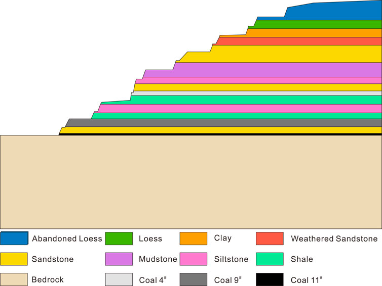
FIGURE 6. Distribution map of rock strata in the Antaibao open-pit mine.
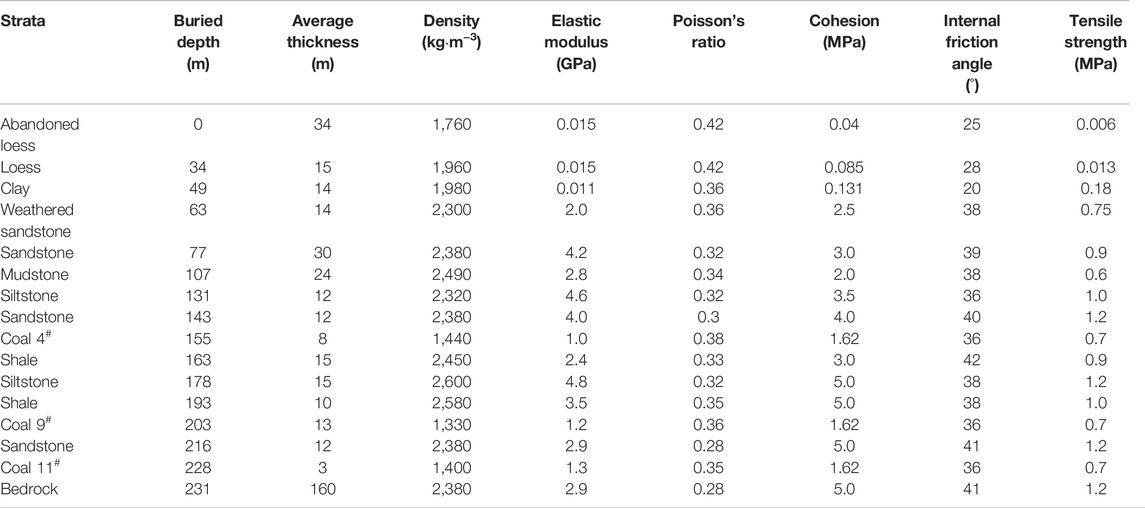
TABLE 7. Buried depth, physical and mechanical parameters of coal seams, and strata in the Antaibao open-pit mine.
4.2 Verifying the Calculation Model Accuracy Based on the Mining of 11# Coal in the Antaibao Open-Pit Mine
The 11# coal is the deepest buried in the minable coal seam of the Antaibao open-pit mine, and its average thickness is 3 m. It is suitable for once mining full height. So, this study verifies the calculation model accuracy based on the mining of 11# coal in the Antaibao open-pit mine. In addition, the maximum mining width and depth of the current continuous shearer-type highwall wall mining system (Addcar) are 3.5 and 350 m, respectively, so set the width, height, and depth of the mining hole as 3.5, 3, and 350 m, respectively. Because it is only to verify the calculation model accuracy, the problem of slope stability is not considered here. Therefore, based on experience, this study sets coal pillars with a width of 3.5 m between mining holes and five mining holes to meet the calculation requirements. Then the three-dimensional model was established by usign Flac3D software according to the geological conditions of the Antaibao open-pit mine. After considering the factors affecting the accuracy of simulation results, such as the model boundary effect, a model with a total of 461,820 nodes, a length of 650 m, a width of 89.5 m, and a height of 391 m is established. The established model is shown in Figure 7. In order to fully verify the calculation accuracy and reliability of the model, this study calculates and verifies the inelastic zone width of the coal pillar under the conditions of 0%, 50%, and 100% filling rates. At the same time, nine points are taken equidistantly from 50 to 330 m away from the mining hole opening as the calculation points, i.e., the inelastic zone width of the coal pillars of nine sections at 50–330 m away from the mining hole opening is calculated. In order to be able to apply the physical and mechanical parameters and other related parameters of the Antaibao open-pit mine 11# coal to the model established in this study, this study performs the average calculation and related processing on the parameters. After average calculation and processing, the parameters are obtained, as shown in Table 8.
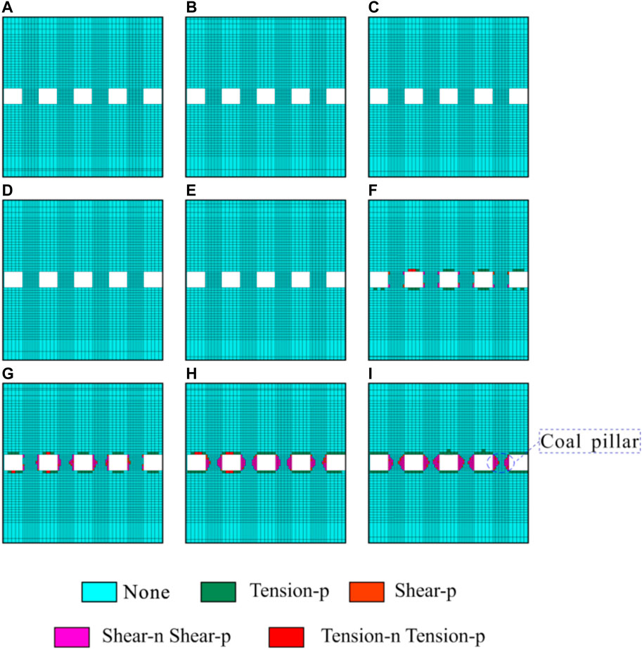
FIGURE 7. Average width for the inelastic zone of the coal pillar in each section under the 0% filling rate condition. (A) 50 m; (B) 85 m; (C) 120 m; (D) 155 m; (E) 190 m; (F) 225 m; (G) 260 m; (H) 295 m; and (I) 330 m.
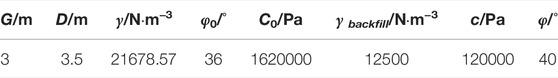
TABLE 8. Physical and mechanical parameters of the Antaibao open-pit 11# coal obtained after average calculation and treatment.
4.2.1 Filling Rate is 0%
Since the filling rate is 0%, i.e., incomplete filling, the parameters of physical and mechanical parameters and other relevant parameters of the Antaibao open-pit mine 11# coal obtained after average calculation are substituted into Eq. 20 and Eqs 30–32, and each calculation point are calculated with MATLAB. After calculation, the inelastic zone width of the coal pillar at each calculation point is obtained, as shown in Table 9. At the same time, to compare the numerical calculation results with the numerical simulation results, take the section at the designated position of the numerical simulation model and count the average width of the inelastic zone of the coal pillar in each section. According to statistics, under the 0% filling rate condition, the average width for the inelastic zone of the coal pillar in each section is shown in Table 9 and Figure 7.

TABLE 9. Inelastic zone width for the coal pillar calculated by numerical calculation and numerical simulation under the 0% filling rate condition.
4.2.2 Filling Rate is 50%
Similarly, since the filling rate is 50%, i.e., incomplete filling, the parameters of physical and mechanical parameters and other relevant parameters of the Antaibao open-pit mine 11# coal obtained after average calculation are substituted into Eq. 20 and Eqs 30–32, and each calculation point is calculated with MATLAB. After numerical calculation, the inelastic zone width for the coal pillar at each calculation point is obtained, as shown in Table 10. After numerical simulation calculation, the average width for the inelastic zone of the coal pillar in each section is shown in Table 10. The plastic failure of each section is shown in Figure 8.

TABLE 10. Inelastic zone width of the coal pillar calculated by numerical calculation and numerical simulation under the 50% filling rate condition.
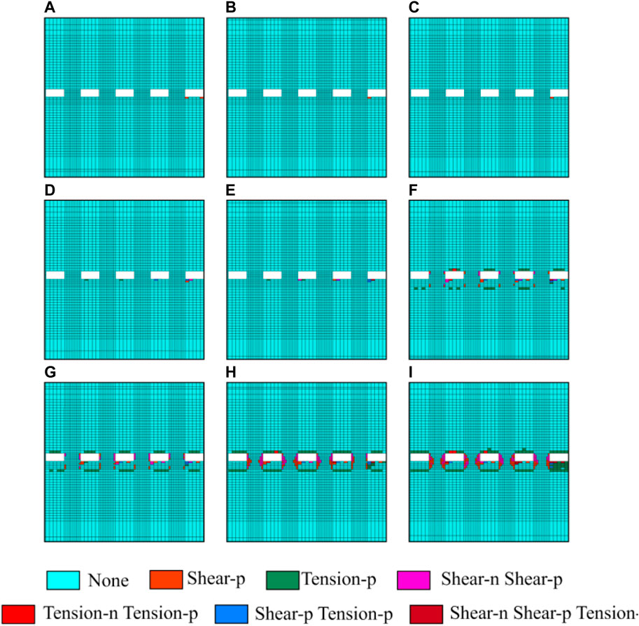
FIGURE 8. Average width of the inelastic zone of the coal pillar in each section under the 50% filling rate condition. (A) 50 m; (B) 85 m; (C) 120 m; (D) 155 m; (E) 190 m; (F) 225 m; (G) 260 m; (H) 295 m; and (I) 330 m
4.2.3 Filling Rate is 100%
Since the filling rate is 100%, i.e., complete filling, the physical and mechanical parameters and other relevant parameters of the Antaibao open-pit mine 11# coal are substituted into Eqs 33–35 and Eq. 36. After numerical calculation, the inelastic zone width of the coal pillar at each calculation point is obtained, as shown in Table 11. After numerical simulation calculation, the average width of the inelastic zone of the coal pillar in each section is shown in Table 11, and the plastic failure of each section is shown in Figure 9.

TABLE 11. Inelastic zone width of the coal pillar calculated by numerical calculation and numerical simulation under the 100% filling rate condition.
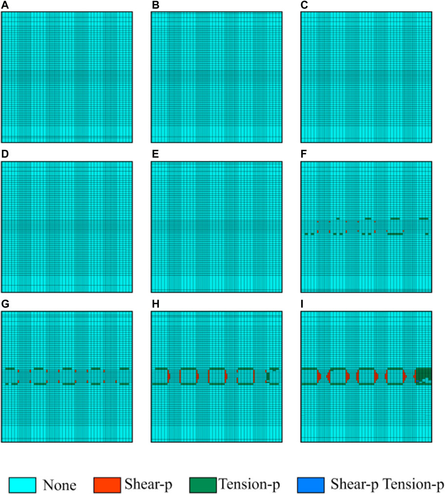
FIGURE 9. Average width of the inelastic zone of the coal pillar in each section under the 100% filling rate condition. (A) 50 m; (B) 85 m; (C) 120 m; (D) 155 m; (E) 190 m; (F) 225 m; (G) 260 m; (H) 295 m; and (I) 330 m.
It can be seen from Tables 10–12 and Figures 7–9 that the model established in this study can comparatively accurately calculate the inelastic zone width of the coal pillar. The inelastic zone width of the coal pillar calculated by the model established in this study is consistent with that calculated by numerical simulation. The maximum error is within 0.4 m. However, from Tables 11, 12 and Figure 10, it is not difficult to find that the results calculated by the model established in this study are generally larger than those calculated by numerical simulation. The reason why such a problem occurs is believed to be caused by two aspects. The first aspect may be that the model established in this study is based on the physical and mechanical parameters and other relevant parameters of the Antaibao open-pit mine 11# coal obtained after average calculation and relevant treatment, while the numerical simulation is calculated directly based on the original parameters, which leads to the result of the numerical calculation is larger than that of numerical simulation; another (He et al., 2022; Niu et al., 2022; Yang et al., 2022) aspect may be that the grid density limits the numerical simulation, making it impossible to calculate the inelastic zone with a width of less than 0.35 m (in the numerical simulation, the grid width at the coal pillar is 0.35 m). Moreover (He et al., 2021; Wu et al., 2022), it also leads to the result of numerical calculation being larger than that of numerical simulation. However, in general, the accuracy of the calculation model for the inelastic zone width of the coal pillar in highwall mining with backfill established in this study can meet the actual production needs. Therefore, it also shows that the model established in this study is reliable and correct and has specific practical value.
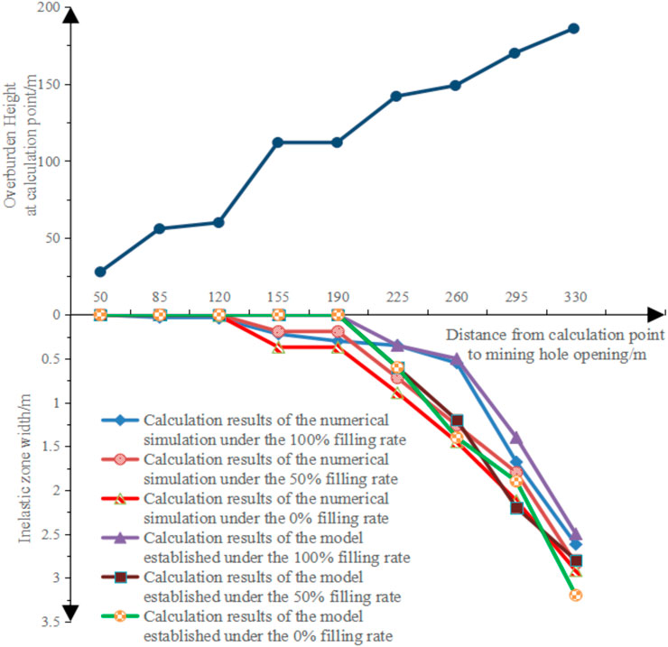
FIGURE 10. Established model and numerical simulation results.
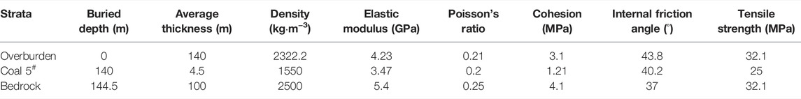
TABLE 12. Buried depth, physical and mechanical parameters of coal seams, and strata in the West Bokaro open-pit mine.\
5 Numerical Simulation Verification Based on the West Bokaro Open-Pit Mine
In the previous chapters, although the calculation model for the inelastic zone width of the coal pillar in the highwall mining with backfill is established after the mechanical derivation and the fitting of the correlation coefficients, the reliability and calculation accuracy of the calculation model needs to be tested. Therefore, in this chapter, the accuracy of the calculation model will be verified based on the geological conditions of the West Bokaro open-pit mine in Northeast India with the study of Lier (2014).
5.1 Verifying the Calculation Model Accuracy Based on the Mining of 5# Coal in the West Bokaro Open-Pit Mine
The occurrence depth and physicomechanical parameters of each coal seam and stratum in the study of Lier (2014) are shown in Table 12. In addition, the coal seam within the minefield is relatively shallow, and the 5# coal, which is the deepest buried, is only 140 m.
The 5# coal is the deepest buried in the minable coal seam of the West Bokaro open-pit mine, and its average thickness is 5.5 m. This study verifies the theoretical formula accuracy based on the mining of 5# coal in the West Bokaro open-pit mine. The study of Lier, 2014 set the width, height, and depth of the mining hole as 3.5, 4.5, and 250 m, respectively. In addition, the coal pillars with a width of 2.9 m between mining holes. In order to fully verify the calculation accuracy and reliability of the theoretical formula, this study calculates and verifies the inelastic zone width of the coal pillar under the conditions of 0% and 100% filling rates. At the same time, nine points are taken equidistantly from 30 to 230 m away from the mining hole opening as the calculation points, i.e., the inelastic zone width of the coal pillars of nine sections at 30–230 m away from the mining hole opening is calculated. The physical and mechanical parameters and other related parameters of the West Bokaro open-pit mine 5# coal is shown in Table 13.
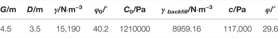
TABLE 13. Physical and mechanical parameters of the West Bokaro open-pit mine 5# coal obtained after average calculation and treatment.
5.2 Inelastic Zone Width Under the 0% Filling Rate Condition of the West Bokaro Open-Pit Mine
Since the filling rate is 0%, i.e., incomplete filling, the parameters of physical and mechanical parameters and other relevant parameters of the West Bokaro open-pit mine 5# coal obtained after average calculation are substituted into Eq 20 and Eqs 30–32, and each calculation point are calculated with MATLAB. After calculation, the inelastic zone width of the coal pillar at each calculation point is obtained, as shown in Table 9. At the same time, to compare the numerical calculation results with the numerical simulation results, take the section at the designated position of the numerical simulation model and count the average width of the inelastic zone of the coal pillar in each section. According to statistics, under the 0% filling rate condition, the average width for the inelastic zone of the coal pillar in each section is shown in Table 14.

TABLE 14. Inelastic zone width for the coal pillar calculated by numerical calculation and numerical simulation under the 0% filling rate condition of the West Bokaro open-pit mine.
5.3 Inelastic Zone Width Under the 100% Filling Rate Condition of the West Bokaro Open-Pit Mine
Similarly, since the filling rate is 100%, i.e., incomplete filling, the parameters of physical and mechanical parameters and other relevant parameters of the Antaibao open-pit mine 5# coal obtained after average calculation are substituted into Eqs 33–35 and Eq. 36, and each calculation point is calculated with MATLAB. After numerical calculation, the inelastic zone width for the coal pillar at each calculation point is obtained, as shown in Table 15.

TABLE 15. Inelastic zone width of the coal pillar calculated by numerical calculation and numerical simulation under the 100% filling rate condition of the West Bokaro open-pit mine.
It can be seen from Tables 14, 15 that the model established in this study can comparatively accurate calculate the inelastic zone width of the coal pillar. The inelastic zone width of the coal pillar calculated by the model established in this study is consistent with that calculated by numerical simulation. The maximum error is within 0.3 m. In general, the accuracy of the calculation model for the inelastic zone width of the coal pillar in highwall mining with backfill established in this study can meet the actual production needs. Therefore, it also shows that the model established in this study is reliable and correct and has a specific practical value.
6 Conclusion
(1) Based on the limit equilibrium method, this study establishes a calculation model for the inelastic zone width of the coal pillar in the highwall mining with backfill. At the same time, in order to improve the model’s practicability, the relationship between model coefficient and geometric parameters such as mining hole width, mining hole height, filling rate, and overburden height is demonstrated. Thus, the calculation model for the inelastic zone width of the coal pillar in highwall mining with backfill without empirical parameters is established.
(2) In this study, the stress distribution of the coal pillar under complete filling and incomplete filling is analyzed and calculated, which shows that with the increase of mining depth, the influence of the filling rate on the width of the inelastic zone of the coal pillar becomes more and more obvious.
(3) In addition, in order to verify the correctness and reliability of the model, this study takes the Antaibao open-pit mine and the West Bokaro mine as the engineering background to carry out numerical simulation to verify the accuracy of the calculation model. Through verification and calculation, it is found that the width of the inelastic zone of the coal pillar calculated by the model established in this study is larger than that of numerical simulation. However, the maximum deviation between the two is less than 0.4 m, which meets the needs of the project.
(4) Therefore, it is fully proved that the calculation model of the inelastic zone width of the coal pillar in filling highwall mining established in this study is correct. The calculation results are more accurate and reliable. Through the research on the width of the plastic zone of the coal pillar under different filling rates, we can make better use of backfill highwall mining to reduce the size of the coal pillar group, further improve the stability of the supporting coal pillar, and liberate more coal resources under the end-slope. It lays a certain foundation for the practical application of highwall mining with backfill technology in the future.
Data Availability Statement
The original contributions presented in the study are included in the article/Supplementary Material; further inquiries can be directed to the corresponding author.
Author Contributions
Conceptualization: JJ and YL; methodology: JJ, LC, and DW; software: LW and YL; formal analysis: JJ, XH, and HY; data curation: JJ and ZJ; writing—original draft preparation: JJ and YL; writing—review and editing: JJ and YL; supervision: LC, DW, and LW; project administration: LC and DW; funding acquisition: LC. All authors have read and agreed to the published version of the manuscript.
Conflict of Interest
The authors declare that the research was conducted in the absence of any commercial or financial relationships that could be construed as a potential conflict of interest.
Publisher’s Note
All claims expressed in this article are solely those of the authors and do not necessarily represent those of their affiliated organizations, or those of the publisher, the editors, and the reviewers. Any product that may be evaluated in this article, or claim that may be made by its manufacturer, is not guaranteed or endorsed by the publisher.
References
Boeut, S. (2015). Design of Auger Highwall Mining: A Case Study at Mae Tan Coal Mine. Thailand: Chulalongkorn University.
Brent, G. F. (2011). Quantifying Eco-Efficiency within Life Cycle Management Using a Process Model of Strip Coal Mining. Int. J. Min. Reclam. Environ. 25, 258–273. doi:10.1080/17480930.2011.553476
Chen, L., Zhang, H., Kang, J., and Jia, G. (2020). Time and Space Evolution Law of Surrounding Rock Deformation under the Influence of Mining. IOP Conf. Ser. Earth Environ. Sci. 525, 12022. doi:10.1088/1755-1315/525/1/012022
Chen, Y. L., Cai, Q. X., Shang, T., and Che, Z. X. (2011). Mining System for Remaining Coal of Final Highwall. J. Min. Sci. 47, 771–777. doi:10.1134/s1062739147060098
Chen, Y., Shimada, H., Sasaoka, T., Hamanaka, A., and Matsui, K. (2013). Research on Exploiting Residual Coal Around Final End-Walls by Highwall Mining System in China. Int. J. Min. Reclam. Environ. 27, 166–179. doi:10.1080/17480930.2012.678768
Dixit, S. K., and Pradhan, M. (20142014). Highwall Mining in India. Cham: Springer International Publishing, 175–187. doi:10.1007/978-3-319-02678-7_18
Duncan Fama, M. E., Shen, B., and Maconochie, P. (2001). Optimal Design and Monitoring of Layout Stability for Highwall Mining. ACARP Project C8033 Final Report. Australia: CSIRO Exploration and Mining Report 887F.
Elmouttie, M., and Karekal, S. (2017). A Framework for Geotechnical Hazard Analysis in Highwall Mining Entries. Procedia Eng. 191, 1203–1210. doi:10.1016/j.proeng.2017.05.296
Fan, M. (2015). Design Programs for Highwall Mining Operations. Master Thesis. Morgantown (West Virginia): West Virginia University.
He, M., Zhang, Z., Zhu, J., and Ning, L. (2022). “Correlation between the Constant Mi of Hoek-Brown Criterion and Porosity of Intact Rock,” in Rock Mechanics and Rock Engineering. Online Published November 2021.
He, M., Zhang, Z., Zhu, J., Li, N., Li, G., and Chen, Y. (2021). Correlation between the Rockburst Proneness and Friction Characteristics of Rock Materials and a New Method for Rockburst Proneness Prediction: Field Demonstration. J. Petroleum Sci. Eng. 205, 108997. doi:10.1016/j.petrol.2021.108997
Huang, J. (2015). Simulation Research for the Influence of Mining Sequence on Coal Pillar Stability under Highwall Mining Method. Geofluids 2021, 8864339.
Kong, X., He, D., Liu, X., Wang, E., Li, S., Liu, T., et al. (2022). Strain Characteristics and Energy Dissipation Laws of Gas-Bearing Coal during Impact Fracture Process. Energy 242, 123028. doi:10.1016/j.energy.2021.123028
Kong, X., Li, S., Wang, E., Wang, X., Zhou, Y., Ji, P., et al. (2021). Experimental and Numerical Investigations on Dynamic Mechanical Responses and Failure Process of Gas-Bearing Coal under Impact Load. Soil Dyn. Earthq. Eng. 142, 106579. doi:10.1016/j.soildyn.2021.106579
Kuznetsova, L. V., and Anfyorov, B. A. (2019). Combined Geotechnology Potentials in the Process of Coal Deposits Integrated Development. IOP Conf. Ser. Earth Environ. Sci. 377, 12003. doi:10.1088/1755-1315/377/1/012003
Li, X.-l., Chen, S.-j., Liu, S.-m., and Li, Z.-h. (2021). AE Waveform Characteristics of Rock Mass under Uniaxial Loading Based on Hilbert-Huang Transform. J. Cent. South Univ. 28 (6), 1843–1856. doi:10.1007/s11771-021-4734-6
Li, X., Cao, Z., and Xu, Y. (2020). Characteristics and Trends of Coal Mine Safety Development, Energy Sources, Part A: Recovery, Utilization and Environmental Effects Philadelphia, 1–19. doi:10.1080/15567036.2020.1852339Characteristics and Trends of Coal Mine Safety DevelopmentEnergy Sources, Part A Recovery, Util. Environ. Eff.
Li, X. L., Chen, S. J., and Wang, S. (2021). Study on In Situ Stress Distribution Law of the Deep Mine Taking Linyi Mining Area as an Example. Adv. Mater. Sci. Eng. 9 (4), 5594181. doi:10.1155/2021/5594181
Li, X. L., Chen, S. J., Zhang, Q. M., Gao, X., and Feng, F. (2021). Research on Theory, Simulation and Measurement of Stress Behavior under Regenerated Roof Condition. Geomechanics Eng. 26 (1), 49–61.
Li, Z., Zhang, X., Wei, Y., and Ali, M. (2021). Experimental Study of Electric Potential Response Characteristics of Different Lithological Samples Subject to Uniaxial Loading. Rock Mech. Rock Eng. 54, 397–408. doi:10.1007/s00603-020-02276-z
Lier, J. S. (2014). Backfill in Highwall Mining: An Assessment of the Possibilities in West Bokaro, India. Master Thesis. Delft (Nederland): Delft University of Technology.
Liu, S., Li, X., Wang, D., and Zhang, D. (2020). Investigations on the Mechanism of the Microstructural Evolution of Different Coal Ranks under Liquid Nitrogen Cold Soaking, Energy Sources, Part A: Recovery, Utilization. and Environmental Effects Philadelphia, 1–17. doi:10.1080/15567036.2020.1841856
Matsui, K., Shimada, H., Kramadibrata, S., and Rai, M. S. (2001). “Some Considerations of Highwall Mining Systems in Coal Mines,” in Proceedings of the 17 International Mining Congress and Exhibition in Turkey (Ankara, 19–22.
Matsui, K., Shimada, H., Sasaoka, T., Furukawa, H., Ueda, T., Yabuki, A., et al. (2004). Highwall Stability Due to Punch Mining at Opencut Coal Mines. Int. J. Surf. Min. Reclam. Environ. 18, 185–204. doi:10.1080/13895260412331315544
Matsui, K., Shimada, H., Sasaoka, T., Ichinose, M., and Kubota, S. (20002018). Highwall Mining System with Backfilling. Mine Planning and Equipment Selection. London: Routledge, 333–338.
Medhurst, T. P., and Brown, E. T. (1998). A Study of the Mechanical Behaviour of Coal for Pillar Design. Int. J. Rock Mech. Min. Sci. 35, 1087–1105. doi:10.1016/s0148-9062(98)00168-5
Mo, S., Canbulat, I., Zhang, C., Oh, J., Shen, B., and Hagan, P. (2018). Numerical Investigation into the Effect of Backfilling on Coal Pillar Strength in Highwall Mining. Int. J. Min. Sci. Technol. 28, 281–286. doi:10.1016/j.ijmst.2017.07.003
Mo, S., Zhang, C., Canbulat, I., and Hagan, P. (2016). A Review of Highwall Mining Experience and Practice.
Niu, Y., Wang, E., and Li, Z. (2022). Identification of Coal and Gas Outburst-Hazardous Zones by Electric Potential Inversion during Mining Process in Deep Coal Seam. Paris: Rock Mech Rock Eng.
Porathur, J. L., Roy, P. P., Shen, B., and Karekal, S. (2017). Highwall Mining: Applicability. London: design & safety.
Porathur, J. L., Srikrishnan, S., Verma, C. P., Jhanwar, J. C., and Pal Roy, P. (2014). Slope Stability Assessment Approach for Multiple Seams Highwall Mining Extractions. Int. J. Rock Mech. Min. Sci. 70, 444–449. doi:10.1016/j.ijrmms.2014.04.023
Salamon, M. M. A. (1967). A Study of the Strength of Coal Pillars. J. S. Afr. I. Min. Metall. 68, 55–67.
Sasaoka, T., Karian, T., Hamanaka, A., Shimada, H., and Matsui, K. (2016). Application of Highwall Mining System in Weak Geological Condition. Int. J. Coal Sci. Technol. 3, 311–321. doi:10.1007/s40789-016-0121-6
Shao-hui, W., Qing-xiang, C., and Fu-ming, L. (2014). Development Status and Suggestions of Open-Cut Mining Technology in China. China: China Mining Magazine, 83–87.
Shen, W., Shi, G., Wang, Y., Bai, J., Zhang, R., and Wang, X. (2021). Tomography of the Dynamic Stress Coefficient for Stress Wave Prediction in Sedimentary Rock Layer under the Mining Additional Stress. Int. J. Min. Sci. Technol. 31, 653–663. doi:10.1016/j.ijmst.2021.04.003
Shimada, H., Chen, Y., Hamanaka, A., Sasaoka, T., Shimada, H., and Matsui, K. (2013). Application of Highwall Mining System to Recover Residual Coal in End-Walls. Procedia Earth Planet. Sci. 6, 311–318. doi:10.1016/j.proeps.2013.01.041
Tao, L. I., and Shuang-shuang, X. (2020). Design Method of Mining Parameters for End Slope Shearer in Surface Mine. Coal Eng. 52, 23–27.
Tiwari, R. P., and Rao, K. S. (2006). Post Failure Behaviour of a Rock Mass under the Influence of Triaxial and True Triaxial Confinement. Eng. Geol. 84, 112–129. doi:10.1016/j.enggeo.2006.01.001
Verma, C. P., Porathur, J. L., Thote, N. R., Roy, P. P., and Karekal, S. (2014). Empirical Approaches for Design of Web Pillars in Highwall Mining: Review and Analysis. Geotech. Geol. Eng. 32, 587–599. doi:10.1007/s10706-013-9713-8
Wang, F., and Zhang, C. (2019). Reasonable Coal Pillar Design and Remote Control Mining Technology for Highwall Residual Coal Resources, 6. Royal Society open science SCImago (n.d.), 181–817. doi:10.1098/rsos.181817
Wang, H., Poulsen, B. A., Shen, B., Xue, S., and Jiang, Y. (2011). The Influence of Roadway Backfill on the Coal Pillar Strength by Numericalinvestigation. Int. J. Rock Mech. Min. Sci. 48, 443–450. doi:10.1016/j.ijrmms.2010.09.007
Wang, M., Tai, C., Zhang, Q., Yang, Z., Li, J., and Shen, K. (2021). Application of Improved and Optimized Fuzzy Neural Network in Classification Evaluation of Top Coal Cavability. Sci. Rep. 11, 19179. doi:10.1038/s41598-021-98630-4
Yan, S., Bai, S., Chang, Z., and Zhao, T. (2019). Theoretical Analysis of Damaged Width & Instability Mechanism of Rib Pillar in Open-Pit Highwall Mining. Adv. Civ. Eng., 6328702.
Wu, H., Zhao, G., and Ma, S. (2022). Failure Behavior of Horseshoe-Shaped Tunnel in Hard Rock under High Stress: Phenomenon and Mechanisms. Trans. Nonferrous Metals Soc. China 32 (3), 639–656. doi:10.1016/s1003-6326(22)65822-9
Xiao-feng, Z. (2015). Study on End-Slope Mining Technology by Continuous Miner. Coal Technol. 34, 28–30.
Xu, G., Liu, H., Fu, B., and Yu, J. (2021). Research and Prospect of Post-peak Strain-Softening Characteristics of Rocks. IOP Conf. Ser. Earth Environ. Sci. 787, 12135. doi:10.1088/1755-1315/787/1/012135
Yang, B., He, M., Zhang, Z., Zhu, J., and Chen, Y. (2022). A New Criterion of Strain Rockburst in Consideration of the Plastic Zone of Tunnel Surrounding Rock. Rock Mech. Rock Eng. 55, 1777–1789. doi:10.1007/s00603-021-02725-3
Yumlu, M., and Ozbay, M. U. (1995). A Study of the Behaviour of Brittle Rocks under Plane Strain and Triaxial Loading Conditions. Int. J. Rock Mech. Min. Sci. Geomechanics Abstr. 32, 725–733. doi:10.1016/0148-9062(95)00025-c
Zhang, W., Cui, Y., Ding, X., Yin, Z., and Wang, Y. (2021). A Novel Tuning Method of Differential Forward Robust PID Controller for Integrating Systems Plus Time Delay Based on Direct Synthesis Method. Int. J. Syst. Sci. 52, 238–262. doi:10.1080/00207721.2020.1825871
Zhang, Y., Xie, Y., Yang, L., Liao, R., and Qiu, T. (2022). Intelligent Prediction of Coal Mine Water Inrush Based on Optimized SAPSO-ELM Model under the Influence of Multiple Factors. Arabian J. Geosciences 15 (430), 1–12. doi:10.1007/s12517-022-09756-2
Keywords: highwall mining with backfill, inelastic zone width, coal pillar, complete filling, incomplete filling
Citation: Jiang J, Lu Y, Cao L, Wang D, Wang L, Han X, Yang H and Jia Z (2022) The Calculation of Inelastic Zone Width of Coal Pillar in Highwall Mining With Backfill. Front. Earth Sci. 10:904703. doi: 10.3389/feart.2022.904703
Received: 25 March 2022; Accepted: 30 May 2022;
Published: 05 July 2022.
Edited by:
Fengqiang Gong, Southeast University, ChinaReviewed by:
Haiqiang Jiang, Northeastern University, ChinaLijie Guo, Beijing General Research Institute of Mining and Metallurgy, China
Peng Huang, China University of Mining and Technology, China
Copyright © 2022 Jiang, Lu, Cao, Wang, Wang, Han, Yang and Jia. This is an open-access article distributed under the terms of the Creative Commons Attribution License (CC BY). The use, distribution or reproduction in other forums is permitted, provided the original author(s) and the copyright owner(s) are credited and that the original publication in this journal is cited, in accordance with accepted academic practice. No use, distribution or reproduction is permitted which does not comply with these terms.
*Correspondence: Ye Lu, bHV5ZV8xODZAMTYzLmNvbQ==