 Jianhua Yang
 Jinshan Sun
 Yongsheng Jia1,2
 Yingkang Yao
 Weipeng Zhang
 Tiejun Tao
95% of researchers rate our articles as excellent or good
Learn more about the work of our research integrity team to safeguard the quality of each article we publish.
Find out more
ORIGINAL RESEARCH article
Front. Earth Sci. , 23 May 2022
Sec. Geohazards and Georisks
Volume 10 - 2022 | https://doi.org/10.3389/feart.2022.903773
This article is part of the Research Topic Deep Rock Mass Engineering: Excavation, Monitoring, and Control View all 22 articles
During blasting excavation in deep rock masses, the in situ stress initially exerted on blast-created free surfaces is rapidly released along with rock cracking by blasting. The rapid stress release can initiate seismic waves transmitting through the medium. In addition to explosion loading, the rapid stress release occurring on blast-created free surfaces is another excitation source of the rock vibration generated in blasting excavation of deep rock masses. In this paper, a theoretical model of seismic wave radiation from a circular blasting excavation in a deep rock mass is first developed to study the frequency differences between explosion seismic waves and stress release-induced seismic waves. Based on this, variational mode decomposition (VMD) is then introduced to separate explosion seismic waves and stress release-induced seismic waves from coupled vibration signals in the frequency domain. By utilizing the VMD separation, the composition and the amplitude and frequency characteristics of the rock vibration monitored in an actual deep tunnel blasting are investigated. The theoretical analysis and field investigation show that the vibration frequency of stress release-induced seismic waves is significantly lower than that of explosion seismic waves. Due to the existence of stress release-induced seismic waves with lower frequency, the coupled vibration amplitude is increased and vibration frequency is reduced. The monitored rock vibration in the near field is dominated by explosion seismic waves. However, in the far field, stress release-induced seismic waves become the major component due to their lower frequency and slower attenuation with distance. Extra care should be taken for the stress release-induced seismic waves in the far field. The stress release-induced seismic waves can be effectively reduced through shortening blast-created free surface sizes and increasing blasthole lengths moderately.
In mining, hydropower and transportation industries, the excavation of deep tunnels is becoming common. Mponeng gold mine in South Africa, which is the deepest mine in the world, has extended down to a depth exceeding 4,350 m (Nex and Kinnaird, 2019). At present in China, there are about 47 coal mines and 32 metal mines excavated at depths between 1,000 and 2,000 m below the ground surface (Xie et al., 2019). The maximum depth of the diversion tunnels in the Jinping-II hydropower station reaches 2,525 m (Fan et al., 2021). Bayu tunnel on the Sichuan-Tibet railway is constructed underground with a maximum depth of 2,080 m (He et al., 2021; Ma and Liu, 2022). With regard to mining and construction at a great depth, the greatest challenge to engineering safety is that the rock mass is subjected to high in situ stress. At a depth greater than 2,000 m below the surface, the in situ stress caused by gravity alone can reach a level comparable to the rock mass compressive strength. According to the in situ stress measurements in South African gold mines, the maximum principal stress at a depth from 1,000 to 3,400 m ranges between 80 and 146 MP (Ogasawara et al., 2014). High in situ stress is the decisive force that causes severe rock damage and hazards in deep mining and construction, such as spalling, v-shaped notches, rockbursts and mine earthquakes (Siren et al., 2015; Xie et al., 2017; Yin et al., 2020; Du et al., 2021; Feng et al., 2021; Kaiser and Moss, 2021; Si et al., 2021; Yang et al., 2021).
When cavities are excavated underground in highly stressed rock masses, some of strain energy stored in the rock masses is released. Theoretical and experimental studies have demonstrated that the speed of the stress or strain energy release has an important effect on the subsequent rock responses (Carter and Booker, 1990; He et al., 2015; Yang J. H. et al., 2018; Li M. et al., 2020; Xu et al., 2020). (Miklowitz, 1978), (Carter and Booker, 1990), (Yang J. H. et al., 2018) and Xu et al. (2020) deemed that the transient release of the stress that was initially exerted on an elastic medium would initiate stress waves transmitting through the medium. Such stress fluctuations are unobvious or even not generated when a slower stress release occurs. For the current mining and construction in deep rock masses, drilling and blasting is still the main method for rock fragmentation and removal (Huo et al., 2021; Chen et al., 2022). During rock fragmentation by blasting, free surfaces are created almost instantaneously and meanwhile the in situ stress initially exerted on these faces is rapidly released. According to the observations by using high-speed photography, this process occurs over a period of several milliseconds or even less, depending on rock and explosive properties, confined conditions and blasthole layouts (He and Yang, 2018; Ding et al., 2021).
Related studies have shown that the rapid in situ stress release occurring during explosion or blasting could induce stress waves or seismic waves, leading to vibration in nearby structures (Toksöz and Kehrer, 1972; Carter and Booker, 1990; Lu et al., 2012; Yang et al., 2022). This phenomenon was first noticed in underground nuclear explosions. In underground nuclear explosion tests, horizontally polarized shear waves (SH and Love waves) were often observed along with P, SV and Rayleigh waves (Toksöz et al., 1965). Theoretically, in a horizontally layered, homogeneous and isotropic medium that is not pre-stressed, an explosive source with radial symmetry should not generate any SH and Love waves. Through numerous studies, it was found that in a pre-stressed rock medium, the rapid stress release along with explosion-induced rock fracture was responsible for the generation of the horizontal shear waves (Toksöz and Kehrer, 1972). (Press and Archambeau, 1962) studied the radiation pattern of the seismic waves due to an induced rupture in a stressed medium. His studies reveal that all the stress conditions give symmetric quadrupole radiation patterns. (Toksöz and Kehrer, 1972). researched the vibration magnitude of the seismic waves resulted from the release of tectonic strain energy during underground nuclear explosions. Their results show that the strain energy related vibration component of the surface waves can exceed the component due to the explosion itself in some cases.
In mining and construction blasts, the seismic waves and structural vibration due to in situ stress release also receive attention in recent years as the excavation depth and the in situ stress level increase. In surveying the rock vibration induced by blasting excavation of deep hydraulic tunnels, (Lu et al., 2012), and (Yang J. et al., 2018) observed that the vibration amplitude was higher than that expected when high in situ stress was present. Through numerical studies, they further concluded that if the in situ stress reached a level higher than 50 MPa, the rapid release of in situ stress could generate comparable vibration velocity to that caused by blast loading (Lu et al., 2012; Cao et al., 2016; Li C. et al., 2020) found that the vibration amplitude of the stress release-induced seismic waves also depended on stress release rates and paths. A non-linear stress release over a shorter period produces a greater vibration velocity. After summarizing these influencing factors, (Lu et al., 2017), developed a semi-empirical formula for predicting the peak particle velocity (PPV) of the stress release-induced seismic waves. In addition, Tao et al. (2013), Zhu et al. (2014), Li M. et al. (2020), and Tao et al. (2021) studied the rock damage responses under the disturbance of rapid in situ stress release. These studies also demonstrate that in mining and construction blasts under high in situ stress conditions, the rapid stress release occurring on blast-created free surfaces is an important dynamic disturbance that cannot be ignored.
It is seen that during blasting excavation in highly stressed rock masses, the monitored rock vibration includes not only seismic waves caused by explosion, but also seismic waves induced by rapid release of in situ stress. However, there is no obvious demarcation point between these two types of waves in the time domain because the in situ stress release on the excavation boundaries occurs along with rock fragmentation by blasting. This brings a great trouble to study the respective vibration component from the field monitoring data. Because of this, the above studies with respect to the stress release-induced seismic waves were conducted mainly by using numerical modeling methods, in which blast loading and stress release can be performed separately. There are few researches reported on the vibration composition analysis based on an effective separation of explosion seismic waves and stress release-induced seismic waves from monitored vibration signals. Recently, a novel variational method, called variational mode decomposition (VMD), was proposed in the field of tone detection, tone separation and noise robustness for decomposing a signal into different modes of unknown but separate spectral bands (Dragomiretskiy and Zosso, 2014). In comparison to existing decomposition models, like the empirical mode decomposition (EMD), the VMD model is theoretically well founded and still easy to understand. Furthermore, this model determines the relevant bands adaptively and estimates the corresponding modes concurrently, thereby properly balancing the errors between them. Due to these advantages, the VMD algorithm has been successfully applied to the identification and separation of rock fracturing microseismic signals form blasting vibration signals (Zhang et al., 2018).
In this study, a mathematical physics model of seismic wave radiation from a circular blasting excavation in a deep rock mass is first developed to analyse the frequency differences between explosion seismic waves and stress release-induced seismic waves. Then the VMD method is utilized to separate explosion seismic waves and stress release-induced seismic waves from the monitored vibration signals in the blasting excavation of the experimental tunnels in China Jinping Underground Laboratory (CJPL). The applicability of the VMD method in the separation is verified by a numerical test. Based on the separated results of the field monitoring data, the composition of the monitored vibration, and the PPV attenuation and frequency characteristics of the respective vibration are investigated.
In tunnel blasting, a row of blastholes are often detonated at the same time. The interactions of explosion-induced stress waves from adjacent blastholes encourage rock cracks to grow preferentially along the connecting line between the adjacent blastholes. The highly cracked zone between the adjacent blastholes becomes a preferential path for detonation gases to escape due to the weakest resistance. The high gas pressure causes the cracks to further extend in the direction of the connecting line. When the cracks between the adjacent blastholes are completely connected, a new free surface is created. It should be noted that in actual rock blasts, particularly in cut hole blasting and caving hole blasting, the shape of blast-created free surfaces are complicated because blast-induced cracks radiate around blastholes and interact with each other. To facilitate theoretical analysis, it is considered that the new free surface is generated along the center line of the blastholes in the same row, as shown in Figure 1. During the formation of the new free surface, the in situ stress initially exerted on this surface is rapidly released along with the blast-induced rock cracking. Therefore, the period of the in situ stress release occurring on blast-created free surfaces approximates the duration of the crack propagation through the zone between adjacent blastholes.
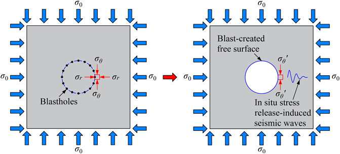
FIGURE 1. Diagram of the rapid in situ stress release occurring on blast-created free surfaces.
Cylindrical charges with detonation initiation at the bottom are commonly used in tunnel blasting. After the explosive at the blasthole bottom is detonated, detonation waves spread upwards at a limited velocity to fire the explosives at other locations. Affected by the propagation of the detonation waves, the dominant wave radiation in the near field of the blastholes is in the form of cone-shaped Mach waves, as shown in Figure 2. The Mach cone is described by the Mach number M = vd/vp and Mach angle θ = arcsin(1/M), where vd is the velocity of detonation and vp is the velocity of wave propagation in the rock medium. It is assumed that the blastholes in the same row are detonated precisely at the same time and generate the same Mach waves. When the Mach wave fronts reach the midpoint P of the connecting line, the zone between the adjacent blastholes is entirely covered by the Mach waves. Then the rock mass between the adjacent blastholes is fully cracked by the Mach waves and a new free surface is created. According to the propagation path of the Mach waves, when the cracks between the adjacent blastholes are completely connected, the length of the longest crack d is (Blair, 2010):
where L is the blasthole length, and S is the space between the adjacent blastholes.
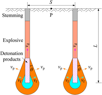
FIGURE 2. Diagram of the mach cone formation around blastholes.
It is assumed that the blast-induced cracks grow at a constant velocity vf. Then the duration for the crack penetration between the adjacent blastholes, i.e., the period of the in situ stress release occurring on blast-created free surfaces can be estimated by tp:
The full-face blasting excavation of deep tunnels normally uses short blastholes with a length ranging from 1.5 to 5.0 m and a space varying from 0.5 to 1.5 m. The velocity of detonation vd = 5,500 m/s, the rock P-wave velocity vp = 4,000 m/s, and the stable crack propagation velocity vf = 0.25vp = 1,000 m/s are considered in this study. Then it is estimated from Eq. 2 that the period of the in situ stress release on blast-created free surfaces is in the range of 1.3–4.2 ms with respect to the short-hole blasting in deep tunnels. For the rock mass with a Young’s modulus E = 10–100 GPa, if the initial stress reaches a level of 20–50 MPa, the strain rate due to the rapid stress release over the period of 100–101 ms can attain 10−1–101 s−1. According to the classification standard of statics and dynamics (Aydan, 2017), this is a dynamic mechanical process in which the inertial force cannot be ignored. The studies of Carter and Booker (1990), Zhu et al. (2014), Yang J. H. et al. (2018) and Tao et al. (2021) also demonstrate that the rapid in situ stress release in a circular excavation generates stress fluctuations transmitting through the medium, as presented in Figure 3. The stress fluctuations give rise to higher circumferential stress and lower radial stress than the final static stress values in a transient time. This causes greater deviatoric stress and thus produces a larger compression-shear damage zone around the excavation under high in situ stress conditions. Beyond the damage zone, the stress waves continue to spread outward as elastic seismic waves, thereby inducing vibration in the surrounding rock mass.
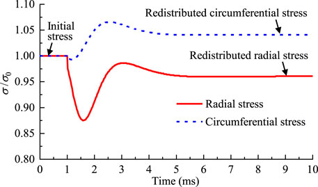
FIGURE 3. Stress waves induced by the rapid in situ stress release in a circular excavation (Yang J. H. et al., 2018).
The PPV characteristics of the rock vibration induced by the rapid in situ stress release have been reported in some literature (Cao et al., 2016; Lu et al., 2017). However, the frequency content of the stress release-induced seismic waves receives much less attention. This section focuses on investigating the frequency differences between explosion seismic waves and stress release-induced seismic waves so as to provide a basis for the following VMD separation between them. The investigation is based on the theoretical solution of the seismic wave radiation from a circular excavation reported by Carter and Booker (1990). To facilitate the theoretical solution, a hydrostatic in situ stress condition is considered. The rock medium is considered to be homogeneous, isotropic and linear elastic. Under these assumptions, the creation of a deep circular cavity by the removal of the stressed rock mass is mechanically equivalent to the application of a traction on the excavation boundary (Carter and Booker, 1990), as shown in Figure 4. The traction load starts from zero and then increases to the initial in situ stress σ0 over the short period tp. The impulsive traction load will induce stress waves to transmit through the rock medium. It is assumed that the explosion pressure and in situ stress are uniform along the blasthole axis. Then the circular excavation can be simplified as a plane strain problem. The motion of applying an impulsive traction load on a circular inner boundary under the condition of plane strain is governed by the equation:
where u is the radial displacement, r is the distance to the center, t is time, and vp is the velocity at which P-waves pass through the rock medium. The quantity vp is given by:
where λ and G are Lame constants, and ρ is the rock density.
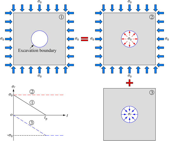
FIGURE 4. Equivalent model of a circular excavation under a hydrostatic in situ stress field.
The initial condition of the motion Eq. 3 is:
where a is the radius of the circular excavation.
The boundary condition of the motion Eq. 3 is the traction load on the inner boundary. It is determined by the path of the rapid in situ stress release occurring on blast-created free surfaces. Unfortunately, the stress release path has not been clearly figured out as the blast-induced crack initiation and growth is complicated. Since the cracks are assumed to spread at a constant velocity, therefore, a linear stress release path, in which the initial in situ stress is reduced from σ0 to zero at a constant rate over the period tp, is adopted in the theoretical solution. Under the action of in situ stress, it is conventionalized that the compressive stress is in positive and the tensile stress is in negative. Then the boundary condition is expressed as:
where σr is the radial stress.
In order to obtain the complete solution to this problem, it is convenient to take a Laplace transform of the governing Eq. 3 as follows (Carter and Booker, 1990):
where the superior bar denotes a Laplace transform, and s is the Laplace transform parameter.
Taking Laplace transforms of the initial and boundary conditions and applying them to Eq. 7 yield (Miklowitz, 1978):
with,
where K1 is the second kind of the modified Bessel functions.
The vibrational waveform at any position is usually represented by the particle velocity history v(r, t). According to the velocity-displacement relationship
Eq. 10 gives the solution to the Laplace transform of the velocity history v(r, t) in terms of the modified Bessel function and its derivative. In order to recover the actual velocity history, Eq. 10 needs to be inverted. This can be achieved efficiently by using the numerical contour integration developed by Talbot (1979). The core of this algorithm is to construct a trapezoidal integration along a special contour, and then the results are obtained through resorting to the residue theorem. Details of the numerical inversion are given in the literature of Talbot (1979) and Cao et al. (2016).
In the theoretical solution to the rock vibration induced by rapid in situ stress release, the following parameters are considered: E = 50 GPa, vp = 4,000 m/s, σ0 = 30 MPa, tp = 2.0 ms, and a = 2.0 m. Figure 5 presents the typical particle velocity history observed at the distance r = 5a = 10 m and the PPV variation with distance obtained from the theoretical solution. The peak vibration velocity due to the rapid in situ stress release reaches 84 cm/s on the excavation boundary at r = a = 2 m. With an increase in the distance, the PPV gradually decreases due to geometric spreading and damping attenuation. At the distance r = 5a = 10 m, the PPV is still as high as 25 cm/s. It exceeds the allowable PPV limit stipulated in the Chinese standard for hydraulic tunnels under blasting vibration, in which the PPV less than 15 cm/s is allowed. Therefore, the rock vibration caused by rapid in situ stress release cannot be ignored with regard to blasting excavation of deep tunnels under high in situ stress conditions.
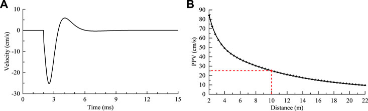
FIGURE 5. Velocity history and PPV of the rock vibration induced by rapid in situ stress release. (A) Velocity history at r = 5a, (B) PPV variation with distance.
The in situ stress release occurring on blast-created free surfaces proceeds along with explosive detonation. The explosion load is another important source of the rock vibration caused by blasting excavation in highly stressed rock masses. The explosion seismic wave radiation from a circular excavation can also be solved theoretically through the above procedure provided that the explosion load is equivalently applied to the excavation boundary. This problem has been studied by Yang J. H. et al. (2018) when investigating the dynamic stress change and rock damage during blasting excavation in a deep circular tunnel. The velocity history of the explosion-induced rock vibration can be obtained by simply replacing Eqs 9, 10 with the following formulas:
where Pe denotes the peak pressure of the equivalent explosion load on the excavation boundary, and tr and td are the rise time and duration of the explosion load. According to the research of Yang J. H. et al. (2018), Pe = 100 MPa, tr = 0.1 ms, and td = 0.9 ms are considered in this theoretical study.
Figure 6A shows the velocity histories of the explosion-induced rock vibration and the stress release-induced rock vibration at r = 5a = 10 m. At this distance, the PPV of the explosion seismic wave is much higher than that of the stress release-induced seismic wave, and the explosion seismic wave dominates the rock vibration at this position. Taking Fourier transforms of the velocity histories gives the amplitude-frequency spectra of these two types of waves, as shown in Figure 6B. For facility of comparison, the normalized amplitude, i.e., the ratio of the current amplitude to its maximum value is presented on the coordinate. For the explosion seismic wave, the vibration frequency is mainly distributed in the band 0–1,000 Hz. In comparison, the frequency distribution of the stress release-induced seismic wave is narrower, mainly lying within 0–400 Hz. The mean or center frequency fm normally serves as a characteristic frequency of the average spectral measure. The mean frequencies are 240 Hz and 91 Hz, respectively, for the explosion seismic wave and the stress release-induced seismic wave. In summary, the frequency of the stress release-induced rock vibration is significantly lower than that of the explosion-induced rock vibration at the same position. This is simply because the vibration frequency depends on loading or unloading rates, and the period of the in situ stress release is much longer than the rise time of the explosion load. The difference in the frequency content makes it possible to use the VMD method to separate explosion seismic waves and stress release-induced seismic waves from monitored rock vibration.
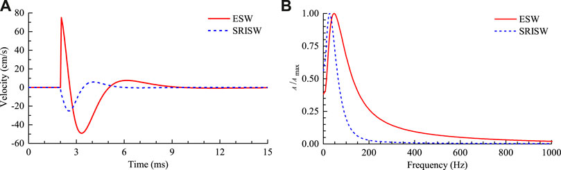
FIGURE 6. Comparisons of the explosion seismic wave (ESW) and the stress release-induced seismic wave (SRISW). (A) Velocity histories at r = 5a, (B) Normalized amplitude-frequency spectra of the velocity histories.
The above theoretical analysis demonstrates that during blasting excavation under high in situ stress conditions, the rapid stress release occurring on blast-created free surfaces can indeed generate non-negligible rock vibration. It also shows that the stress release-induced rock vibration is significantly different from the explosion-induced rock vibration in frequency content. In this section, the rock vibration composition and characteristics for blasting excavation in highly stressed rock masses are further analyzed by using field monitoring data. As mentioned earlier, the field data analysis relies on an effective separation of explosion seismic waves and stress release-induced seismic waves from the monitored vibration. In the present study, the VMD method is introduced in an attempt to achieve this separation. The VMD is a signal processing method based on the frequency domain, and hence the above frequency content analysis can provide a theoretical basis for the following VMD separation.
The field rock vibration monitoring was carried out during the blasting excavation of the experimental tunnels in China Jinping Underground Laboratory (CJPL). CJPL is located in Jinping Mountain in Sichuan Province, China. It is the deepest underground laboratory currently in operation in the world. By utilizing the construction adit as the entrance, four groups of experimental tunnels and traffic tunnels and two connecting drifts are excavated for this underground laboratory, as shown in Figure 7. The excavation size of each experimental tunnel is 130 m long, 14 m wide and 14 m high. The drilling and blasting method is used in the excavation of the experimental tunnels. In order to minimize the adverse effects of blasting, the blasting excavation of the experimental tunnels is divided into three horizontal layers. Each layer has a height of 8.5 m, 4.0 m and 1.5 m, respectively.
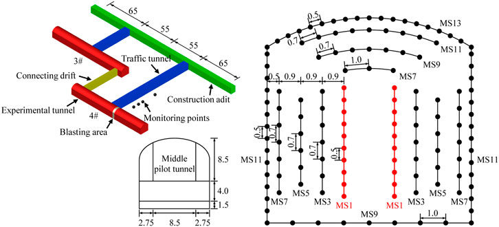
FIGURE 7. Blasting design of the pilot tunnel and the arrangement of the vibration monitoring.
In the upper layer, a horizontal pilot tunnel measuring 8.5 m wide and 8.5 m high is first created in the middle prior to the two sides. The blasthole arrangement and detonation network for the pilot tunnel excavation are shown in Figure 7. The blastholes in an excavation cycle are detonated sequentially in seven delays with time intervals of 50–200 ms. Short holes with a length of 3.5 m and a diameter of 50 mm are used in the pilot tunnel blasting. The space between the adjacent blastholes in the same delay varies from 0.5 to 1.0 m. The tunnels and drifts in CJPL are excavated at depths greater than 2000 m, and the maximum excavation depth is 2,375 m. The in situ stress tests in the experimental tunnels show that the maximum principal stress reaches 50−70 MPa. For the pilot tunnel that is first excavated, it is a typical case of rock blasting excavation under high in situ stress. Therefore, in this case, the rapid in situ stress release occurring on blast-created free surfaces is likely to be an important excitation source to induce rock vibration.
During the blasting excavation of the pilot tunnel in No. Four experimental tunnel, four vibration sensors are installed inside the surrounding rock mass of the traffic tunnel to monitor the rock vibration, as shown in Figure 7. At each monitoring point, a triaxial velocity sensor is used to measure the transverse, vertical and longitudinal velocity histories. A total of five tests were carried out in the rock vibration monitoring. The distance from the monitoring points to the explosion source varies from 20 to 80 m.
The monitored vibration velocity histories at each point include seven sub-waveforms, corresponding to the seven delays of blasting mentioned above. Among these sub-waveforms, the one caused by the cut hole blasting in the first delay has the maximum vibration velocity due to its dense charge and lack of sufficient free surfaces. Furthermore, in this delay, the blasting excavation boundary (the connecting line of the blastholes in the first delay) is subjected to the highest in situ stress. The rock vibration resulted from the rapid stress release is also the most obvious in this delay. Therefore, the sub-waveforms produced in the cut hole blasting in the first delay are chosen for the following analysis. Figure 8 presents the velocity histories of the sub-waveforms recorded at No. One monitoring point in the first test. These waves are body waves as the monitoring points are placed inside the surrounding rock mass. Under this scenario, the interference of surface waves on the following analysis can be eliminated.
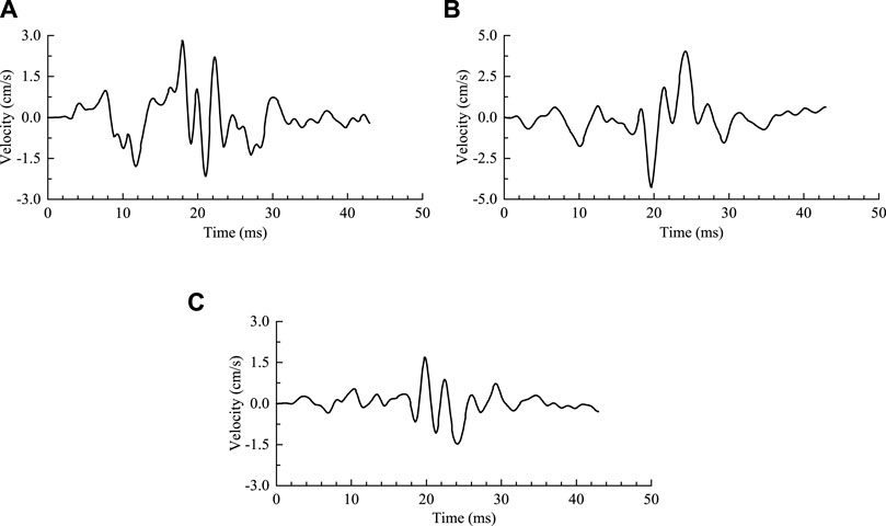
FIGURE 8. Velocity histories monitored on site during the cut hole blasting. (A) Transverse component, (B) Vertical component, (C) Longitudinal component.
The vibration waveforms presented in Figure 8 contain explosion seismic waves and stress release-induced seismic waves. These two types of waves do not have an obvious demarcation point in the time domain, but have a significant difference in the frequency domain. Because of this, the VMD method, which is based on the frequency domain, is utilized to separate the explosion seismic waves and the stress release-induced seismic waves from the monitored vibration waveforms. The VMD method is a novel, entirely non-recursive and adaptive variational method for decomposing an input signal into a discrete number of intrinsic mode functions (Dragomiretskiy and Zosso, 2014). The VMD model looks for an ensemble of modes that reconstruct the given input signal optimally, and each mode is band-limited around a center frequency. In this model, the relevant bands are determined adaptively and the corresponding modes are estimated concurrently, thereby balancing the errors between them properly. Compared with the EMD model, the VMD model is theoretically well founded and overcomes the problems of modal aliasing and boundary effects in the EMD. In addition, it gets rid of the requirement of predefining base functions that are used in the wavelet approaches.
The goal of VMD is to decompose an input signal f(t) into K discrete sub-signals (intrinsic mode functions), uk(t), which have specific sparsity properties when reconstructing the input signal. The bandwidth of each mode is chosen to be its sparsity prior. Each mode is considered to be mostly compact around a center frequency ωk(t), which is determined along with the decomposition. The intrinsic mode function uk(t) is defined as an amplitude-modulated-frequency-modulated signal, written as:
where Ak(t) is the instantaneous amplitude of uk(t), and φk(t) is the instantaneous phase, and t is time.
In order to assess the bandwidth of each mode and reconstruct the given input signal exactly, the sum of the bandwidths of all modes is required to be minimized and the sum of all modes should be equal to the input signal. Then the resulting constrained variational problem is expressed as (Dragomiretskiy and Zosso, 2014):
where {uk} = {u1, … , uK} and {ωk} = {ω1, … , ωK} are respectively the shorthand notations for the sets of all modes and their center frequencies, δ(t) is the Dirac distribution function, j is the imaginary unit, and *denotes convolution.
In addressing the constrained problem, a quadratic penalty term α and a Lagrangian multiplier λ(t) are introduced to render the problem unconstrained. The combination of these two terms benefits both from the nice convergence properties of the quadratic penalty and the strict execution of the constraint by the Lagrangian multiplier (Dragomiretskiy and Zosso, 2014). Consequently, the augmented Lagrangian equation La is obtained as follows:
The solution to the original constraint problem Eq. 14 is the saddle point of the augmented Lagrangian equation in a sequence of iterative sub-optimizations (Rockafellar, 1973). The solutions of the sub-optimizations are the following:
where ω is the frequency, the superscript ^ denotes a Fourier transform, and τ is the update parameter of the Lagrangian multiplier.
The solutions of the sub-optimizations are plugged into the alternating direction method of multipliers (ADMM) algorithm to update the modes and their center frequencies and search for the saddle points. Then the optimal solution to the constrained variational problem is obtained, and the input signal is decomposed into an ensemble of band-limited modes and their center frequencies. The steps for the complete optimization of VMD are as follows. First, an original signal f(t) and the total number of modes to be decomposed K are input. Then the mode functions
where ε is the tolerance of convergence. In this study, ε = 10−7 is considered.
The VMD is a robust signal decomposition method in the frequency domain that can adaptively seek the optimal bandwidth and center frequency for each mode. In this study, the VMD is introduced in attempt to decompose the monitored rock vibration signals mentioned above into explosion seismic waves and stress release-induced seismic waves. Before performing VMD separation on the field monitoring data, the applicability of the VMD method in the vibration separation needs to be verified. The theoretically calculated seismic waves as shown in Figure 6A are simple in waveforms and frequency content, which are quite different from the rock vibration measured on site. Therefore, the theoretical waveforms are incompetent to verify the applicability of VMD in the vibration separation. With regard to the field monitoring vibration, it is coupled waveforms that contain explosion seismic waves and stress release-induced seismic waves. The respective vibration waveforms cannot be measured directly and compared with the VMD separation results. In this regard, numerical modeling is an optimal approach as it can simulate both the respective vibration waves and the coupled vibration waves. Furthermore, the simulated vibration waveforms through three-dimensional modeling are more similar to the measured vibration signals. Therefore, a numerical test is conducted in this study to verify the applicability of VMD. In the verification, the simulated coupled vibration caused by the combined actions of explosion loading and rapid in situ stress release is first presented. Then the VMD method is employed to decompose the coupled vibration into explosion seismic waves and stress release-induced seismic waves. Finally, the separated waves are compared with the simulated vibrations respectively caused by explosion loading and stress release.
We have carried out a three-dimensional modeling of the rock vibrations caused by explosion loading, rapid stress release and their combined actions for the blasting excavation of the pilot tunnel in CJPL. The numerical modeling is performed in the FEM software ANSYS/LS-DYNA by using its implicit and explicit solutions in sequence. The initial in situ stress is first pre-loaded on the exterior boundaries of the numerical model. Then the implicit solver in ANSYS is launched to compute the element stress and deformation. These information is transmitted to the explicit program LS-DYNA to initialize the stress and deformation of the explicit elements. After that, the explosion load is applied and the stress initially exerted on the blast-created free surfaces is rapidly released in a specific path. The explicit solver in LS-DYNA is finally implemented to compute the element velocity under the dynamic loads. The geometric model, material parameters, loads and boundary conditions, simulation procedures and verification of the modeling have been given detailedly in our previous publication (Yang J. et al., 2018). Therefore, these details about the numerical modeling are not repeated in this paper.
Figure 9 presents the simulated vibration velocity histories caused by the combined actions of explosion loading and rapid in situ stress release for the cut hole blasting. These simulated waveforms agree well with the field monitoring vibration (Yang J. et al., 2018). These waveforms as the input signals are decomposed in the following by using the VMD method for its applicability verification. In the VMD decomposition, it is crucial to choose an appropriate K for the number of the decomposed intrinsic mode functions. If K is too small, it will result in insufficient decomposition of the input signals, and some characteristic information may be submerged. In contrast, an excessive K value will cause undue decomposition, leading to modal aliasing. According to the above theoretical analysis, the rock vibration generated in the blasting excavation of highly stressed rock masses involves two motivation sources, explosion loading and rapid stress release. Therefore, K = 2 is considered in this decomposition. The intrinsic mode functions obtained by the VMD decomposition are sub-signals arranged from low frequency to high frequency. The frequency of the stress release-induced vibration is much lower than that of the blasting vibration. Then the first-order intrinsic mode function is the sub-signals for the stress release-induced vibration, and the second-order mode is the sub-signals for the blasting vibration.
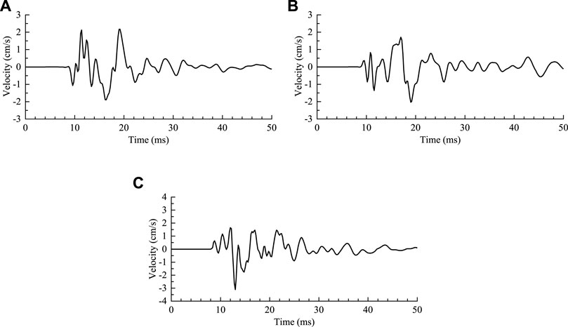
FIGURE 9. Simulated vibration velocity histories caused by the combined actions of explosion loading and rapid stress release. (A) Transverse component, (B) Vertical component, (C) Longitudinal component (Yang J. et al., 2018).
Figure 10 presents the separated explosion seismic waves and stress release-induced seismic waves from the simulated coupled vibration shown in Figure 9. The respective vibration waves obtained by the numerical modeling are also given in this figure for comparison. It is seen that the separated waveforms based on the VMD method agree well with the numerical results, whether in vibration amplitude, frequency or duration. The PPV and center frequency of the respective vibration waves are summarized in Tables 1, 2 respectively. For the explosion seismic waves, the relative differences between the VMD separation and the numerical simulation do not exceed 14% in the PPV and 7% in the center frequency. For the stress release-induced seismic waves, the maximum relative differences are 18% in the PPV and 4% in the center frequency. These qualitative and quantitative comparisons show that the VMD method can realize an effective separation of explosion seismic waves and stress release-induced seismic waves from the coupled vibration. In the following, this method is applied to the field monitoring vibration signals. Based on the VMD separation, the composition and characteristics of the rock vibration caused by the blasting excavation of the pilot tunnel are analyzed.
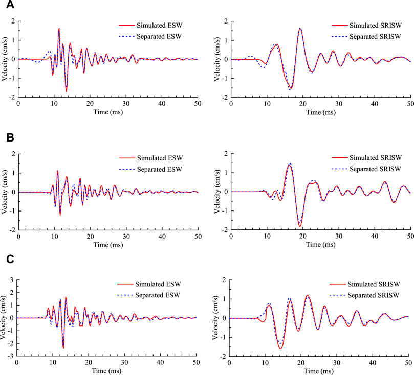
FIGURE 10. Comparisons between the separated seismic waves based on VMD and the simulated seismic waves. (A) Transverse component, (B) Vertical component, (C) Longitudinal component.
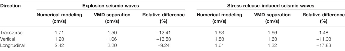
TABLE 1. PPV of the respective seismic waves obtained by the numerical modeling and the VMD separation.
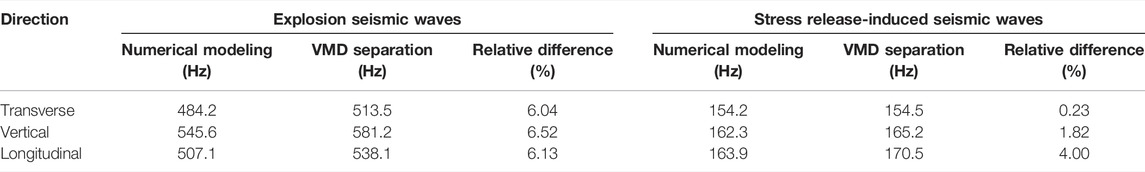
TABLE 2. Center frequency of the respective seismic waves obtained by the numerical modeling and the VMD separation.
The VMD separation is performed on the monitored vibration signals in Figure 8, obtaining the velocity histories of the explosion seismic waves and the stress release-induced seismic waves, as shown in Figure 11. At No.1 observation point in the first test, the transverse, vertical and longitudinal PPVs of the explosion seismic waves are 1.79 cm/s, 2.38 cm/s and 1.26 cm/s, respectively. For the stress release-induced seismic waves, the corresponding PPVs are 1.57 cm/s, 2.39 cm/s and 0.77 cm/s, respectively. At this point, the vibration amplitude of the stress release related seismic waves approaches or even exceeds the amplitude of the blasting vibration. Clearly, for the blasting excavation of the deep tunnels in CJPL, the rapid in situ stress release occurring on blast-created free surfaces is an important motivation source that causes vibration in the surrounding rock. This is mainly due to the high in situ stress field in this project.
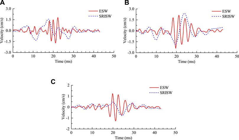
FIGURE 11. Seismic waves separated from the monitored vibration signals. (A) Transverse component, (B) Vertical component, (C) Longitudinal component.
Taking Fourier transforms on the the velocity histories in Figure 11 gives the normalized amplitude-frequency spectra of the separated seismic waves, as shown in Figure 12. For the explosion seismic waves, the frequency is mainly distributed in the band from 200 to 600 Hz. The center frequencies of the transverse, vertical and longitudinal components are 413.4 Hz, 310.0 Hz, and 326.9 Hz, respectively. In comparison, the frequency band of the stress release-induced seismic waves is much narrower, mainly in the band from 0 to 300 Hz. Its center frequency is lower accordingly, with 101.4 Hz, 88.9 Hz, and 97.6 Hz for the three components. In conclusion, the vibration frequency of the stress release-induced seismic waves is significantly lower than that of the explosion seismic waves. This coincides with the theoretical calculation result above.
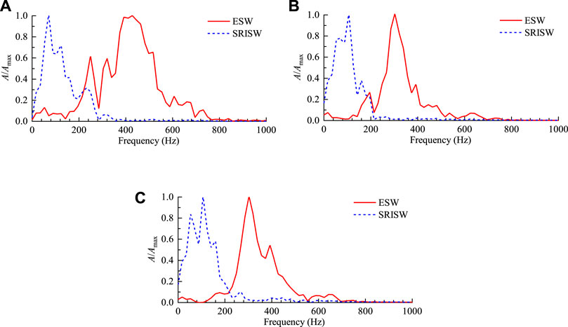
FIGURE 12. Normalized amplitude-frequency spectra of the separated seismic waves. (A) Transverse component, (B) Vertical component, (C) Longitudinal component.
Figures 11, 12 present the separated seismic waves and their spectra for the vibration signals recorded at No.1 monitoring point in the first test. The vibration signals monitored at the other points and tests are also decomposed into explosion seismic waves and stress release-induced seismic waves by the VMD method. After decomposition, their PPV and characteristic frequency are listed in Table 3. For ease of presentation and comparison, the peak velocity given in this table is the PPV of the resultant velocity, and the characteristic frequency is the average of the center frequencies of the three velocity components. Among the twenty monitoring points in the five tests, there are ten points where the stress release-induced seismic waves exceed the explosion seismic waves in the resultant PPV. The average center frequency of the explosion seismic waves is mostly higher than 250 Hz. While with regard to the stress release-induced seismic waves, the average center frequency mainly lies between 70 and 200 Hz. Admittedly, at very few monitoring points, the average center frequency of the explosion seismic waves falls between 200 and 250 Hz. The average center frequency of the stress release related seismic waves at a few points also falls within this band. However, at the same monitoring point, the average center frequency of the stress release related seismic waves is always obviously lower than that of the explosion seismic waves. This shows the conclusions obtained from Figures 11, 12 are also valid for the vibration signals measured at the other points.
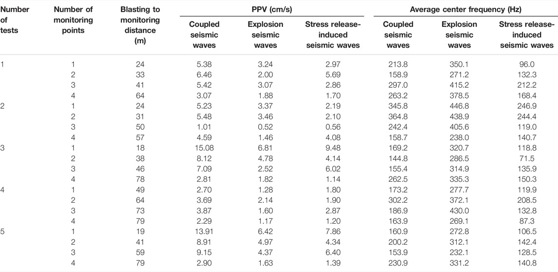
TABLE 3. PPV and average center frequency of the separated seismic waves.
From the comparison between the coupled seismic waves and the explosion seismic waves, it is seen that the rock vibration amplitude is increased and the vibration frequency is reduced due to the stress release-induced seismic waves. Clearly, this coupling effect causes the seismic waves arising from the blasting excavation of deep tunnels to be more harmful to structures than the shallow tunnel blasting under the same blasting design. From the perspective of the mechanical process, the explosion seismic waves are generated first, followed by the stress release-induced seismic waves. Because the two types of seismic waves arrive the monitoring points at different time and also they have different wavelengths, the peak velocity attainment time is different for the respective seismic waves. Therefore, the PPV of the coupled seismic waves is less than the sum of the PPVs of the respective seismic waves.
It is generally acknowledged that the PPV of the explosion seismic waves decays with distance as per a power function (Yilmaz, 2016; Rodríguez et al., 2021). For comparison, the PPV attenuation of the stress release-induced seismic waves is also considered to follow the power function law. Fitting the discrete PPVs at the twenty monitoring points in Table 3 by using a power function yields the empirical attenuation laws for the respective seismic waves, as shown by the curves in Figure 13. It is well known that during seismic wave propagation in a rock medium, the seismic attenuation factor Q will change the relative frequency content of the spectrum as the travel distance increases. Amplitudes at high frequencies decay faster than amplitudes at low frequencies. This causes high-frequency vibration to decay faster with increasing distance. Because the vibration frequency of the stress release-induced seismic waves is lower than that of the explosion seismic waves, the PPV of the stress release-induced seismic waves decays more slowly with distance. Within 20 m distance from the explosion source, the peak velocity of the stress release-induced seismic waves is smaller than that of the explosion seismic waves. However, as the distance further increases, the stress release-induced vibration exceeds the blasting vibration due to its slower attenuation. In the far field beyond 20 m distance, the stress release-induced seismic waves become the major component of the rock vibration. It is common knowledge that low-frequency vibration is more damaged to structures than high-frequency vibration at the same PPV. Therefore, extra care should be taken for the stress release-induced rock vibration with lower frequency, particularly in the far field.
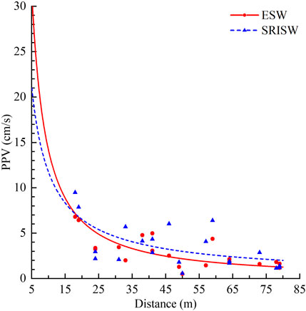
FIGURE 13. PPV attenuation with distance of the separated seismic waves.
Figures 13, 14 presents the average center frequencies of the respective seismic waves at various monitoring points. Likewise, power functions are employed to best fit these discrete frequency values. The average center frequency of the stress release-induced seismic waves is significantly lower than that of the explosion seismic waves. For both, the average center frequencies decrease with an increase in the travel distance. However, the decreasing amplitudes are not significant, especially for the stress release-induced seismic waves since the distance span of vibration monitoring is only 60 m. From the comparison between the attenuation indexes of the fitted power functions, the average center frequency of the explosion seismic waves declines faster with increasing distance. This is because the explosion seismic waves have higher frequency, and rock mediums contribute to propagation of low-frequency seismic waves by filtering high-frequency seismic waves.
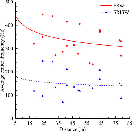
FIGURE 14. Dependence of average center frequency on distance of the separated seismic waves.
The above theoretical analysis and field investigation show that the stress release-induced seismic wave is an important component of the rock vibration generated in blasting excavation of deep tunnels. During the blasting excavation of the pilot tunnel in CJPL, the explosive with a density varying from 950 to 1,300 kg/m3 and a velocity of detonation ranging from 3,500 to 5,500 m/s is used. In the cut hole blasting, the blasthole diameter is 50 mm, the explosive column diameter is 32 mm, and the space between the adjacent blastholes is 0.5 m. From these blasting parameters, it can be estimated that the equivalent explosion pressure on the blasting excavation boundary varies from 40 to 130 MPa (Yang J. et al., 2018). The in situ stress in this project reaches 50−70 MPa. The rock mass near the blasting work face may be subjected to higher in situ stress due to local stress concentration. Therefore, the rapid stress release occurring on blast-created free surfaces can produce a comparable vibration velocity to the explosion loading. Moreover, the seismic waves induced by the rapid stress release decay more slowly with distance. Then it is quite possible that the stress release-induced rock vibration exceeds the blasting vibration in the far field. Overall, the explosion seismic waves dominate the near-field rock vibration, and the stress release-induced seismic waves can become the major component of the far-field rock vibration. Therefore, during blasting excavation of deep tunnels under high in situ stress, the seismic waves caused by the rapid stress release cannot be ignored. Unfortunately, this concern has not attracted sufficient attention in current blasting design and vibration control for deep tunnel blasting.
In current vibration control of tunnel blasting, the widely used measures are to reduce charge weight and optimize charge structures to achieve the purpose of minimizing the explosion-induced vibration. This is certainly adequate for blasting of shallow tunnels. However, during deep tunnel blasting under high in situ stress, it may be necessary to reduce the stress release-induced vibration. According to the theoretical solution formula in Eq. 10, the rock vibration caused by the rapid stress release depends on the in situ stress level σ0, the stress release period tp, the size of blast-created free surfaces a, and the rock properties vp. As the stress level and the size of blast-created free surfaces increase, the velocity of the stress release-induced vibration increases accordingly. The vibration velocity decreases with an increase in the period of the stress release. Intact rock masses with higher P-wave velocity generate greater vibration velocity than loose rock masses. The in situ stress level and the rock properties cannot be easily changed. However, the size of blast-created free surfaces and the period of the stress release can be adjusted through designing blasthole arrangements and detonation sequences.
With regard to the cut hole blasting of the pilot tunnel in CJPL in Figure 7, the size of blast-created free surfaces can be reduced through changing the number of the blastholes detonated in the first delay. If ten blastholes (five holes on each side) are detonated in the first delay, the vertical side length of the blast-created free surfaces will be reduced from 4.5 m to 2.0 m. The equivalent excavation radius under the same area will be shortened from 1.7 m to 1.1 m accordingly. In the theoretical model in Section 2, when the circular excavation radius is changed from 1.7 m to 1.1 m, the vibration PPV due to the rapid stress release decreases from 18.8 cm/s to 8.6 cm/s at 10 m distance, as shown in Figure 15A. A significant reduction of 54% is reached in the PPV. Furthermore, as the excavation radius decreases, the vibration frequency becomes higher, as presented in Figure 15B. This shows that reducing the size of blast-created free surfaces can achieve effective control of the stress release-induced rock vibration.
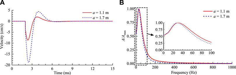
FIGURE 15. Velocity histories and amplitude-frequency spectra of the stress release-induced vibration under different excavation radiuses. (A) Velocity histories at r = 10 m, (B) Normalized amplitude-frequency spectra of the velocity histories.
According to Eq. 2, the period of the rapid stress release occurring on blast-created free surfaces relies on the blasthole length and space for a given rock mass. The blasthole arrangement at a larger length and space generates a longer period, corresponding to a smaller vibration velocity. As mentioned earlier, short blastholes with a length ranging from 1.5 to 5.0 m and a space varying from 0.5 to 1.5 m are normally used in the full-face blasting of deep tunnels. The blasthole length is much greater than the blasthole space in size. Therefore, in Eq. 2, the period of the rapid stress release is dominated by the blasthole length. In the cut hole blasting of the pilot tunnel in CJPL, the blasthole length of 3.5 m is used. If the blasthole length is changed from 3.5 m to 5.0 m, the period of the stress release will be prolonged from 2.7 ms to 3.8 ms. Based on the theoretical model in Section 2, the PPV of the stress release-induced vibration under the different blasthole lengths is shown in Figure 16. When the blasthole length is increased from 3.5 m to 5.0 m, the PPV at 10 m distance is reduced from 19.7 cm/s to 13.4 cm/s, with a reduction of 32%. Clearly, increasing the blasthole length moderately is effective in extending the stress release period and reducing the stress release-induced rock vibration.
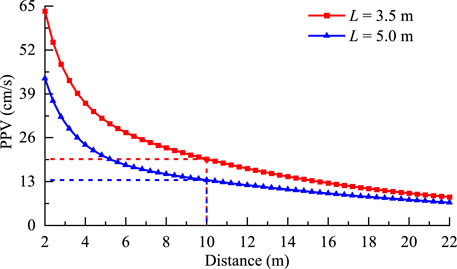
FIGURE 16. PPV of the stress release-induced vibration under different blasthole lengths.
The above discussion indicates that in deep tunnel blasting, smaller blasting excavation boundaries and larger blasthole lengths are conducive to control the rock vibration due to the rapid in situ stress release. However, a larger blasthole length means a greater explosive charge weight if the charge density remains constant. It will increase the rock vibration caused by the explosion loading. Therefore, in order to determine an optimal blasthole arrangement for minimizing the coupled rock vibration, the combined effects of explosion loading and rapid stress release need to be analyzed. In this regard, the theoretical model developed in this paper is limited. For example, the detonation propagation along explosive columns and the effect of blasthole length on explosion seismic wave radiation cannot be considered. Furthermore, the interval time between the initiation of explosion loading and the start of rapid stress release cannot be accurately determined. In the similar theoretical model developed by Yang J. H. et al. (2018), it is considered that the in-situ stress release begins when the explosion pressure falls to a level equal to the initial stress on excavation boundaries. However, this is a rough estimation because the microscopic rock fracture between adjacent blastholes, which fundamentally causes in-situ stress release, is not handled properly. Alternatively, the numerical modeling is a more promising approach, in which explosive detonation, rock fracture between adjacent blastholes and in situ stress release on blast-created free surfaces can be reproduced.
During blasting excavation of deep tunnels under high in situ stress, the in situ stress initially exerted on blast-created free surfaces is rapidly released along with rock fragmentation by blasting. The theoretical analysis conducted in this study shows that the rapid in situ stress release can induce considerable seismic waves, resulting in vibration in surrounding rock masses. The vibration frequency of stress release-induced seismic waves is significantly lower than that of explosion seismic waves. The difference in the frequency content makes it possible to separate explosion seismic waves and stress release-induced seismic waves from monitored vibration signals. The VMD method is demonstrated to be an effective approach to achieve this separation. Based on the VMD separation, the composition and characteristics of the rock vibration monitored in the cut hole blasting of the pilot tunnel in CJPL are investigated. The field monitoring data investigation shows that the rock vibration amplitude is increased and the vibration frequency is reduced due to stress release-induced seismic waves. The rock vibration in the near field is dominated by explosion seismic waves. In the far field, stress release-induced seismic waves become the major composition due to their lower frequency and slower attenuation with distance. Through shortening blast-created free surface sizes and increasing blasthole lengths moderately, the rock vibration caused by the rapid stress release can be effectively reduced.
The purpose of this study is to reveal the composition and characteristics of the rock vibration generated in blasting excavation of deep tunnels through theoretical analysis and field investigation. It has been demonstrated that under high in situ stress, the seismic wave due to the rapid stress release is an important vibration component. The structural responses and safety criterions under the coupling of explosion seismic waves and stress release-induced seismic waves need to be studied in future research.
The original contributions presented in the study are included in the article/Supplementary Material, further inquiries can be directed to the corresponding author.
JY and JS: investigation, software, and writing original draft; YJ and YY: project administration and supervision; JY and WZ: writing, review and editing; TT: investigation. All authors have read and agreed to the published version of the manuscript.
This work was supported by the National Natural Science Foundation of China (51969015 and 52179102), the Open Research Program of Hubei Key Laboratory of Blasting Engineering (Jianghan University) (HKLBEF202007), and the Natural Science Foundation of Jiangxi Province (20204BCJ23002).
The authors declare that the research was conducted in the absence of any commercial or financial relationships that could be construed as a potential conflict of interest.
All claims expressed in this article are solely those of the authors and do not necessarily represent those of their affiliated organizations, or those of the publisher, the editors and the reviewers. Any product that may be evaluated in this article, or claim that may be made by its manufacturer, is not guaranteed or endorsed by the publisher.
Blair, D. (2010). Seismic Radiation from an Explosive Column. Geophysics 75 (1), E55–E65. doi:10.1190/1.3294860
Cao, W., Li, X., Tao, M., and Zhou, Z. (2016). Vibrations Induced by High Initial Stress Release during Underground Excavations. Tunn. Undergr. Space Technol. 53, 78–95. doi:10.1016/j.tust.2016.01.017
Carter, J. P., and Booker, J. R. (1990). Sudden Excavation of a Long Circular Tunnel in Elastic Ground. Int. J. Rock Mech. Min. Sci. Geomechanics Abstr. 27 (2), 129–132. doi:10.1016/0148-9062(90)94861-m
Chen, H., Qiu, X., Shi, X., Zhang, J., Huo, X., and Li, D. (2022). Experimental Study on Fracturing Characteristics of Double-Hole Blasting under Static Stresses. Front. Earth Sci. 9, 829258. doi:10.3389/feart.2021.829258
Ding, C., Yang, R., and Yang, L. (2021). Experimental Results of Blast-Induced Cracking Fractal Characteristics and Propagation Behavior in Deep Rock Mass. Int. J. Rock Mech. Min. Sci. 142, 104772. doi:10.1016/j.ijrmms.2021.104772
Dragomiretskiy, K., and Zosso, D. (2014). Variational Mode Decomposition. IEEE Trans. Signal Process. 62 (3), 531–544. doi:10.1109/tsp.2013.2288675
Du, K., Sun, Y., Zhou, J., Wang, S.-f., Tao, M., Yang, C., et al. (2021). Low Amplitude Fatigue Performance of Sandstone, Marble, and Granite under High Static Stress. Geomech. Geophys. Geo-energ. Geo-resour. 7 (3), 68. doi:10.1007/s40948-021-00266-1
Fan, Y., Cui, X., Leng, Z., Zheng, J., Wang, F., and Xu, X. (2021). Rockburst Prediction from the Perspective of Energy Release: a Case Study of a Diversion Tunnel at Jinping II Hydropower Station. Front. Earth Sci. 9, 711706. doi:10.3389/feart.2021.711706
Feng, G.-l., Chen, B.-r., Jiang, Q., Xiao, Y.-x., Niu, W.-j., and Li, P.-x. (2021). Excavation-Induced Microseismicity and Rockburst Occurrence: Similarities and Differences between Deep Parallel Tunnels with Alternating Soft-Hard Strata. J. Cent. South Univ. 28 (2), 582–594. doi:10.1007/s11771-021-4623-z
He, C., and Yang, J. (2018). Dynamic Crack Propagation of Granite Subjected to Biaxial Confining Pressure and Blast Loading. Lat. Am. J. Solids Struct. 15 (6), e45. doi:10.1590/1679-78254463
He, M., e Sousa, L. R., Miranda, T., and Zhu, G. (2015). Rockburst Laboratory Tests Database - Application of Data Mining Techniques. Eng. Geol. 185, 116–130. doi:10.1016/j.enggeo.2014.12.008
He, S., Lai, J., Zhong, Y., Wang, K., Xu, W., Wang, L., et al. (2021). Damage Behaviors, Prediction Methods and Prevention Methods of Rockburst in 13 Deep Traffic Tunnels in China. Eng. Fail. Anal. 121, 105178. doi:10.1016/j.engfailanal.2020.105178
Huo, X., Shi, X., Qiu, X., Chen, H., Zhou, J., Zhang, S., et al. (2021). Study on Rock Damage Mechanism for Lateral Blasting under High In Situ Stresses. Appl. Sci. 11 (11), 4992. doi:10.3390/app11114992
Kaiser, P. K., and Moss, A. (2022). Deformation-Based Support Design for Highly Stressed Ground with a Focus on Rockburst Damage Mitigation. J. Rock Mech. Geotechnical Eng. 14 (1), 50–66. doi:10.1016/j.jrmge.2021.05.007
Li, C., Li, X., and Liang, L. (2020a). Dynamic Response of Existing Tunnel under Cylindrical Unloading Wave. Int. J. Rock Mech. Min. Sci. 131, 104342. doi:10.1016/j.ijrmms.2020.104342
Li, M., Mei, W., Pan, P.-Z., Yan, F., Wu, Z., and Feng, X.-T. (2020b). Modeling Transient Excavation-Induced Dynamic Responses in Rock Mass Using an Elasto-Plastic Cellular Automaton. Tunn. Undergr. Space Technol. 96, 103183. doi:10.1016/j.tust.2019.103183
Lu, W., Fan, Y., Yang, J., Yan, P., and Chen, M. (2017). Development of a Model to Predict Vibrations Induced by Transient Release of In-Situ Stress. J. Vib. Control 23 (11), 1828–1843. doi:10.1177/1077546315601594
Lu, W., Yang, J., Yan, P., Chen, M., Zhou, C., Luo, Y., et al. (2012). Dynamic Response of Rock Mass Induced by the Transient Release of In-Situ Stress. Int. J. Rock Mech. Min. Sci. 53, 129–141. doi:10.1016/j.ijrmms.2012.05.001
Ma, K., and Liu, G. (2022). Three-Dimensional Discontinuous Deformation Analysis of Failure Mechanisms and Movement Characteristics of Slope Rockfalls. Rock Mech. Rock Eng. 55 (1), 275–296. doi:10.1007/s00603-021-02656-z
Miklowitz, J. (1978). The Theory of Elastic Waves and Waveguides. Amsterdam: North-Holland Publishing Company.
Nex, P. A. M., and Kinnaird, J. A. (2019). “Minerals and Mining in South Africa,” in The Geography of South Africa. Editors J. Knight, and C. Rogerson (Cham: Springer), 27–35. doi:10.1007/978-3-319-94974-1_4
Ogasawara, H., Nakatani, M., Durrheim, R., Naoi, M., Yabe, Y., Moriya, H., et al. (2014). “Observational Studies of the Rock Mass Response to Mining in Highly Stressed Gold Mines in South Africa,” in Deep Mining 2014: Proceedings of the 7th International Conference on Deep and High Stress Mining. Editors M. Hudyma, and Y. Potvin (Perth: Australian Centre for Geomechanics), 123–137. doi:10.36487/ACG_rep/1410_06_Ogasawara
Press, F., and Archambeau, C. (1962). Release of Tectonic Strain by Underground Nuclear Explosions. J. Geophys. Res. 67 (1), 337–343. doi:10.1029/jz067i001p00337
Rockafellar, R. T. (1973). A Dual Approach to Solving Nonlinear Programming Problems by Unconstrained Optimization. Math. Program. 5 (1), 354–373. doi:10.1007/bf01580138
Rodríguez, R., García de Marina, L., Bascompta, M., and Lombardía, C. (2021). Determination of the Ground Vibration Attenuation Law from a Single Blast: a Particular Case of Trench Blasting. J. Rock Mech. Geotechnical Eng. 13 (5), 1182–1192. doi:10.1016/j.jrmge.2021.03.016
Si, X., Huang, L., Li, X., Ma, C., and Gong, F. (2021). Experimental Investigation of Spalling Failure of D-Shaped Tunnel under Three-Dimensional High-Stress Conditions in Hard Rock. Rock Mech. Rock Eng. 54 (6), 3017–3038. doi:10.1007/s00603-020-02280-3
Siren, T., Kantia, P., and Rinne, M. (2015). Considerations and Observations of Stress-Induced and Construction-Induced Excavation Damage Zone in Crystalline Rock. Int. J. Rock Mech. Min. Sci. 73, 165–174. doi:10.1016/j.ijrmms.2014.11.001
Talbot, A. (1979). The Accurate Numerical Inversion of Laplace Transforms. IMA J. Appl. Math. 23 (1), 97–120. doi:10.1093/imamat/23.1.97
Tao, J., Shi, A.-C., Li, H.-T., Zhou, J.-W., Yang, X.-G., and Lu, G.-D. (2021). Thermal-mechanical Modelling of Rock Response and Damage Evolution during Excavation in Prestressed Geothermal Deposits. Int. J. Rock Mech. Min. Sci. 147, 104913. doi:10.1016/j.ijrmms.2021.104913
Tao, M., Li, X., and Li, D. (2013). Rock Failure Induced by Dynamic Unloading under 3D Stress State. Theor. Appl. Fract. Mech. 65, 47–54. doi:10.1016/j.tafmec.2013.05.007
Toksöz, M. N., Harkrider, D. G., and Ben-Menahem, A. (1965). Determination of Source Parameters by Amplitude Equalization of Seismic Surface Waves: 2. Release of Tectonic Strain by Underground Nuclear Explosions and Mechanisms of Earthquakes. J. Geophys. Res. 70 (4), 907–922. doi:10.1029/jz070i004p00907
Toksoz, M. N., and Kehrer, H. H. (1972). Tectonic Strain Release by Underground Nuclear Explosions and its Effect on Seismic Discrimination. Geophys. J. Int. 31 (1–3), 141–161. doi:10.1111/j.1365-246x.1972.tb02364.x
Xie, G., Yin, Z., Wang, L., Hu, Z., and Zhu, C. (2017). Effects of Gas Pressure on the Failure Characteristics of Coal. Rock Mech. Rock Eng. 50 (7), 1711–1723. doi:10.1007/s00603-017-1194-2
Xie, H., Konietzky, H., and Zhou, H. W. (2019). Special Issue “Deep Mining”. Rock Mech. Rock Eng. 52 (5), 1415–1416. doi:10.1007/s00603-019-01805-9
Xu, H., Yang, X.-G., Zhang, J.-H., Zhou, J.-W., Tao, J., and Lu, G.-D. (2020). A Closed-form Solution to Spherical Wave Propagation in Triaxial Stress Fields. Int. J. Rock Mech. Min. Sci. 128, 104266. doi:10.1016/j.ijrmms.2020.104266
Yang, C., Tang, J., Huang, D., Wang, L., Sun, Q., and Hu, Z. (2021). New Crack Initiation Model for Open-Flawed Rock Masses under Compression-Shear Stress. Theor. Appl. Fract. Mech. 116, 103114. doi:10.1016/j.tafmec.2021.103114
Yang, J.-h., Wu, Z.-n., Sun, W.-b., Yao, C., and Wang, Q.-h. (2022). Numerical Simulation on Radiation and Energy of Blast-Induced Seismic Waves in Deep Rock Masses. J. Cent. South Univ. 29 (2), 645–662. doi:10.1007/s11771-022-4908-x
Yang, J. H., Jiang, Q. H., Zhang, Q. B., and Zhao, J. (2018a). Dynamic Stress Adjustment and Rock Damage during Blasting Excavation in a Deep-Buried Circular Tunnel. Tunn. Undergr. Space Technol. 71, 591–604. doi:10.1016/j.tust.2017.10.010
Yang, J., Lu, W., Li, P., and Yan, P. (2018b). Evaluation of Rock Vibration Generated in Blasting Excavation of Deep-Buried Tunnels. KSCE J. Civ. Eng. 22 (7), 2593–2608. doi:10.1007/s12205-017-0240-7
Yilmaz, O. (2016). The Comparison of Most Widely Used Ground Vibration Predictor Equations and Suggestions for the New Attenuation Formulas. Environ. Earth Sci. 75 (3), 269. doi:10.1007/s12665-015-5011-5
Yin, Z., Chen, W., Hao, H., Chang, J., Zhao, G., Chen, Z., et al. (2020). Dynamic Compressive Test of Gas-Containing Coal Using a Modified Split Hopkinson Pressure Bar System. Rock Mech. Rock Eng. 53, 815–829. doi:10.1007/s00603-019-01955-w
Zhang, X.-L., Jia, R.-S., Lu, X.-M., Peng, Y.-J., and Zhao, W.-D. (2018). Identification of Blasting Vibration and Coal-Rock Fracturing Microseismic Signals. Appl. Geophys. 15 (2), 280–289. doi:10.1007/s11770-018-0682-9
Keywords: deep tunnel, blasting excavation, in situ stress release, rock vibration, variational mode decomposition
Citation: Yang J, Sun J, Jia Y, Yao Y, Zhang W and Tao T (2022) Composition and Characteristics of Rock Vibration Generated in Blasting Excavation of Deep Tunnels. Front. Earth Sci. 10:903773. doi: 10.3389/feart.2022.903773
Received: 24 March 2022; Accepted: 02 May 2022;
Published: 23 May 2022.
Edited by:
Zhiqiang Yin, Anhui University of Science and Technology, ChinaReviewed by:
Gongda Lu, Sichuan University, ChinaCopyright © 2022 Yang, Sun, Jia, Yao, Zhang and Tao. This is an open-access article distributed under the terms of the Creative Commons Attribution License (CC BY). The use, distribution or reproduction in other forums is permitted, provided the original author(s) and the copyright owner(s) are credited and that the original publication in this journal is cited, in accordance with accepted academic practice. No use, distribution or reproduction is permitted which does not comply with these terms.
*Correspondence: Jinshan Sun, c3Vuamluc2hhbkBqaHVuLmVkdS5jbg==
Disclaimer: All claims expressed in this article are solely those of the authors and do not necessarily represent those of their affiliated organizations, or those of the publisher, the editors and the reviewers. Any product that may be evaluated in this article or claim that may be made by its manufacturer is not guaranteed or endorsed by the publisher.
Research integrity at Frontiers
Learn more about the work of our research integrity team to safeguard the quality of each article we publish.