- 1School of Environment and Civil Engineering, Jiangnan University, Wuxi, China
- 2State Key Laboratory of Geohazard Prevention and Geoenvironmental Protection, Chengdu University of Technology, Chengdu, China
- 3Key Laboratory of Disaster Prevention and Structural Safety of Ministry of Education, College of Civil Engineering and Architecture, Guangxi University, Nanning, China
- 4Guangxi Key Laboratory of Disaster Prevention and Engineering Safety, College of Civil Engineering and Architecture, Guangxi University, Nanning, China
Three-dimensional stability analysis of soil slopes remains a hot topic in the field of geotechnical engineering. Considering the fluid–solid coupling effect, this study performs a number of numerical analyses on the stability of a 3D excavation slope located in the Wuxi Taihu Tunnel, China. Three typical cases of the issued slope are investigated, i.e., the slope at the initial state, with the water-stop curtain, and with both the water-stop curtain and concrete-sprayed layer. The shear strength reduction method was adopted to determine the factor of safety (FOS) of the slope. The distributions of pore pressures and wetting lines, the horizontal and vertical displacements, and the critical slip surface are presented. The results indicate that the water-stop curtain can prevent the groundwater seepage effectively. The water-stop curtain and concrete-sprayed layer are effective in restraining the slope deformation, altering the critical slip surface, and improving the slope safety.
Introduction
The water-level variations and seepages in soils are the main factors that trigger the failure of excavations. A fluid–solid coupling effect commonly exists during the water infiltration process. The stress field in soils is governed by the seepage force, and in turn the deformations of soil lead to changes in its pores and thereafter altering the seepage of water in it (e.g., Adapa et al., 2021). The shear strength of soil is also declined. In engineering practice, however, the stability assessments of excavation slopes are mainly based on the plane strain assumption (e.g., Li et al., 2018; Kumar et al., 2019; Sun et al., 2019; Chen et al., 2021; Hailu, 2021), and the 3D effect is usually neglected leading to conservative results (Hu et al., 2018; Scaringi et al., 2018; Wang et al., 2019a; Wang et al., 2020).
A mount of research studies on the stability of excavation slopes has been reported (e.g., Li et al., 2018; Wang et al., 2019b; Kumar et al., 2019; Chen et al., 2021; Hailu, 2021). The results show that the maximum stress and displacement obtained by the coupled methods are larger than those obtained by the uncoupled ones and resemble the measured values. The numerical approaches, such as the finite element method, have gained significant attention in geotechnical engineering and are, especially applicable for the stability problem of specific, well-defined slopes with accurate geotechnical parameters (e.g., Tschuchnigg et al., 2015; Cheng et al., 2021; Dong et al., 2021; Zhou et al., 2022). Furthermore, the slopes in inhomogeneous and anisotropic soils under complex boundary conditions can also be handled satisfactorily. Recently, Chen et al. (2021) studied the combined effect of seismic excitation and rainwater seepage on slope stability. Considering the seepage conditions, Hailu (2021) performed a finite element modeling to predict the stability of an embankment dam. In total, three distinct operational cases are considered for the dam analysis, but these results are based on plane strain assumptions. Based on the calculated stress by the finite element method, Su and Shao (2021) developed a 3D slope stability analysis method and presented the critical slip surface according to the two-stage particle swarm optimization. In these analyses, the suction-related effects are ignored. The soil in practice, however, is mostly unsaturated, and neglecting the suction effect produces more conservative results (Wang et al., 2019a; Sun et al., 2019; Wang et al., 2020; Wang et al., 2021).
In this study, an excavation slope of the Wuxi Taihu Tunnel in China was examined using the finite element method. Considering the fluid–solid coupling effect, a finite element model combined with the seepage field is established. The suction effect is considered by altering the soil permeability coefficient and the saturation that both change with respect to the soil matric suction. A series of numerical simulations are carried out regarding the slopes at the initial state, with the water-stop curtain, and with both the water-stop curtain and the concrete-sprayed layer.
Background
Project Overview
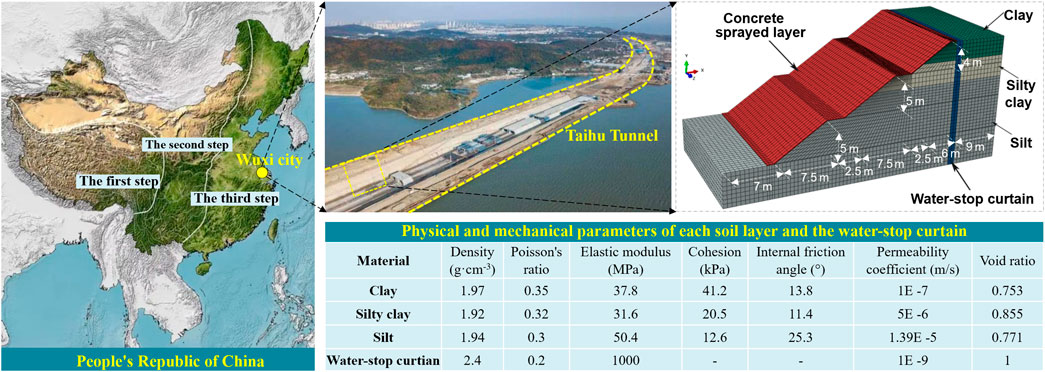
The Taihu Tunnel, located in Wuxi China, is a lake-bottom tunnel of the Su-Xi-Chang southern expressway, as illustrated in Figure 1. The tunnel has a total length of 3,740 m. The width of the foundation pit falls in the range of 43–44 m, and the excavation depth ranges from 2.63 to 20.20 m. The water depth of Taihu Lake is 1.60–5.20 m, and the water level in the tunnel crossing section is generally 1.46–3.03 m.

FIGURE 1. Three-dimensional finite element model of the excavation slope located in the Taihu Tunnel, Wuxi China.
A certain section of the tunnel characterized by three stages is considered. The slope ratio is 1:1.5 with a total height of 14 m. The width of the platform is 2.5 m, and the slope surface is sprayed with C20 concrete with a thickness of 0.1 m. A closed water-stop curtain is adopted to drain the water and is placed 1.0 m outside the slope crest.
A three-dimensional finite element model of the issued slope was established with a geometric size of 42.0 m × 19.0 m × 20.0 m, as illustrated in Figure 1. As the gradient of these three stages is nearly identical with each other, the equivalent gradient of these three stages is postulated in the analysis. The thickness of the water-stop curtain is 1.0 m and is placed along the whole slope. The total width of the slope is assumed to be 28 m, i.e., the width of the sliding soil mass is two times the slope height. The geological survey data show that the excavation is made of clay, silty clay, and silt with the thickness of each soil layer being 2.8, 3.2, and 13 m, respectively. The physical and mechanical parameters for each soil layer and the water-stop curtain are listed in the table. The concrete damage plasticity model is employed to predict the mechanic and deformation behavior of the concrete-sprayed layer. The eight-node hexahedron C3D8P pore pressure element is adapted for the soil and the water-stop curtain. The mesh division of the 3D slope is shown in the graph.
Fluid–Solid Coupling Analysis
The stress field and seepage field in the soil depend on each other. The coupling effect of the seepage field and stress field yields stress and strain in geotechnical materials, altering the stress field and displacement field of soils and therefore resulting in ground subsidence. Conversely, the changes in the stress and strain field lead to the change in soil porosity and permeability, thus altering the fluid seepage and soil consolidation process.
The direct coupling method based on Biot’s consolidation theory is adopted by ABAQUS software. According to the principle of virtual work and the conservation law of matter, the equilibrium equation and seepage continuity equation of the coupled seepage and stress field are obtained, respectively. The Galerkin method is used to solve various flow equations by means of the finite element discretization technique combined under the pore pressure boundary conditions and the flow boundary conditions. The fluid–solid coupling equation can be expressed as:
where K and C are matrices; t is time; u and p are displacements and pore water pressures of element nodes, respectively.
In ABAQUS, solving the stress-seepage coupling problem can be realized by setting the analysis step, and the definition of the seepage boundary can be realized by modifying the keywords.
The strength reduction method pioneered by Zienkiewicz et al. (1975) has been widely used by many scholars in slope stability problems. Based on ABAQUS software, the reduction of soil strength parameters is realized by changing the soil parameters defined by field variables. The inflection points of the displacement of some characteristic positions (e.g., slope crest) are used as the evaluation standard in the slope stability analysis.
Material Strength Parameters
The fast consolidation shear index is adopted, and the physical and mechanical parameters of each soil layer and the water-stop curtain are shown in Figure 1. Experimental evidence and site investigations show that the mechanical and physical properties of unsaturated soils differ with those of saturated soils (Xu, 2004; Gao et al., 2021; Wang et al., 2022). The soil permeability coefficient and saturation both change with the matric suction and their relations can be found as:
where Kws is the permeability coefficient of saturated soil; ua and uw are the pore air pressure and pore water pressure, respectively; Sr, Si, and Sn are the saturation, residual saturation, and maximum saturation, respectively; Si and Sn are taken as 0.08 and 1, respectively; aw, bw, cw, as, bs, and cs are taken as 1,000, 0.01, 1.7, 1, 5 × 10⁻⁵, and 3.5, respectively. Generally, the matric suction declines rapidly as the saturation increases. The permeability coefficient increases sharply as the saturation increases and depends on soil types closely.
Model Boundary Conditions
In three-dimensional slope stability analysis, selection of appropriate boundary conditions is crucial in producing realistic results. The mechanical boundary conditions influence the shape of the failure surface and therefore the corresponding FOS of the slope. In this analysis, the displacement in a normal direction of the left and right boundaries of the model is restricted, that is, the displacement in the x-direction is 0. The bottom boundary of the model is fully constrained, that is, the displacements in x-, y-, and z-directions are all 0. The slope surface and platform are free drainage boundaries, and the rest are impervious boundaries. The left and right sides are subjected to hydrostatic pressure, that is, the water head load. The pore pressure boundary that changes linearly with the elevation is specified to meet the known water head condition, and the pore pressure at the slope surface is set to be zero.
Results
Slope at the Initial Condition
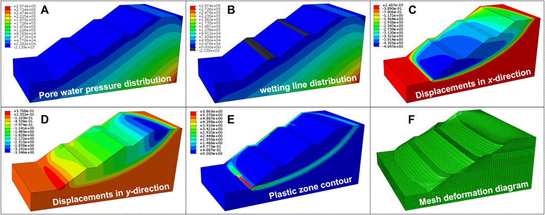
Considering the coupling effect of seepage and stress fields, the excavation at the initial condition is studied, as illustrated in Figure 2. The pore water pressure and wetting line distributions, the displacements in x- and y-directions, the plastic zone contour, and the mesh deformation diagram of the slope failure are presented. It can be found from the graph that the pore water pressure is of layered distribution and remains identical in the normal direction of the slope profile. As the soil depth increases, the pore water pressure increases nearly linearly. The maximum displacement in the x-direction of the slope is 4.667 m and occurs at the toe of the first stage. The maximum displacement in the y-direction of the slope occurs in the upper part. Furthermore, the contour of a potential sliding zone can be observed evidently from the graph, which resembles the actual slope failures. The factor of safety of the slope can be obtained based on the strength reduction method. The factor of safety of the slope at the initial condition is 1.559 and is consistent with that yield from the Swedish slice method.

FIGURE 2. (A) Pore water pressure distribution; (B) wetting line distribution; (C) displacement in x-direction; (D) displacement in y-direction; (E) plastic zone contour; and (F) mesh deformation diagram of the slope at the initial condition.
Effect of the Water-Stop Curtain
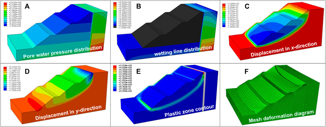
With the presence of the water-stop curtain, the pore water pressure and wetting line distributions, the displacements in x- and y-directions, the plastic zone contour, and the mesh deformation diagram of the slope are obtained, as illustrated in Figure 3. Obviously, with the presence of the water-stop curtain, the pore water pressure variation is slowed down significantly and drops sharply near the water-stop curtain. Furthermore, with the presence of the water-stop curtain, the wetting line distributions of the slope change from a saturated state to an unsaturated one (i.e., the black zone in the graph). The minimum pore water pressure at the slope shoulder drops from −2.139 × 10³ Pa to −5.782 × 10⁴ Pa, indicating that the water-stop curtain is effective in preventing the seepage of water in the soil outside the slope into the soil inside the slope.

FIGURE 3. (A) Pore water pressure distribution; (B) wetting line distribution; (C) displacement in x-direction; (D) displacement in y-direction; (E) plastic zone contour; and (F) mesh deformation diagram of the slope with the water-stop curtain.
Compared with the slope at the initial state, the displacement in the x-direction at the toe is small when the water-stop curtain is considered. This means that the water-stop curtain can reduce the slope sliding effectively. When the water-stop curtain is used, the maximum sliding displacement of the slope is reduced by 28.22% from 4.667 to 3.350 m. The displacement in the y-direction at the slope toe is increased. This indicates that the water-stop curtain is effective in maintaining slope stability. As the distance between the slope toe increases, the displacement in the y-direction is increased slightly. The sliding zone of the slope with the water-stop curtain is identical to that of the slope at the initial state. Only the slip surface near the slope crest is different between these two cases. This is due to the presence of the water-stop curtain that the extension of the critical sliding zone to the slope crest is restricted, and the soil behind the water-stop curtain cannot slide. The factor of safety of the slope with the water-stop curtain is 1.725 and is increased by 10.65% compared with that of the slope at the initial condition.
Effect of the Concrete-Sprayed Layer
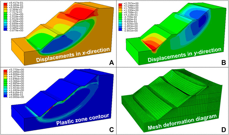
With the presence of the concrete-sprayed layer, the pore water pressure and wetting line distributions, the displacements in x- and y-directions, the plastic zone contour, and the mesh deformation diagram of the slope are obtained, as illustrated in Figure 4. Because the concrete-sprayed layer is placed on the slope surface, the pore water pressure and the wetting line distributions are nearly unchanged.

FIGURE 4. (A) Displacement in x-direction; (B) displacement in y-direction; (C) plastic zone contour; and (D) mesh deformation diagram of the slope with the concrete-sprayed layer.
Compared with the slope with the water-stop curtain, when the concrete-sprayed layer is considered, the displacement in the x-direction at the slope toe becomes small. The sliding displacement is reduced by 41.25% from 3.350 to 1.968 m when the concrete-sprayed layer is used. This indicates that the concrete-sprayed layer can reduce the slope sliding effectively. Furthermore, it is interesting to be noticed that, when the slope is covered with a concrete-sprayed layer, the displacement in the x-direction of the second platform becomes positive. This is because of the constraint of the concrete. Compared with the slope at the initial state, when the concrete-sprayed layer is considered, the displacement in the y-direction at the slope toe is increased. The displacement in the y-direction is increased slightly as the distance between the slope toe increases. The displacement at the slope crest is only 0.929 m, indicating that the concrete-sprayed layer can restrict the slope sliding effectively.
When the slope is covered with a concrete-sprayed layer, the sliding slip surface becomes deeper and passes below the slope toe. A “deep” sliding occurs in this case. For the slope at the initial condition, the maximum plastic strain region occurs at the slope toe, while for the slope with a water-stop curtain, the maximum plastic strain region occurs at the junction of the soil with the water-stop curtain. The factor of safety of the slope with the concrete-sprayed layer is 1.841 and is increased by 18.09% compared with that of the slope at the initial condition. Therefore, the concrete-sprayed layer can improve the slope stability and is significant in slope failure prevention.
Conclusion
This study performed a series of numerical simulations on the stability of a 3D excavation slope located in the Wuxi Taihu Tunnel, China. The fluid–solid coupling effect is considered. In total, three typical cases, i.e., the slopes at the initial state, with the water-stop curtain, and with both the water-stop curtain and concrete-sprayed layer were studied. The variations of pore pressures and wetting lines on the slope stability were studied. The horizontal and vertical displacements and the critical slip surface were presented. Based on the results, the following conclusions can be drawn:
1) The water-stop curtain can restrict the water seepage and improve the wetting line effectively. The extension of the critical sliding zone to the slope crest is restricted, and the slope stability is improved slightly.
2) The water-stop curtain and the concrete-sprayed layer can reduce the sliding displacement significantly. Compared with that of the slope at the initial state, the sliding displacement of the slope with the water-stop curtain is reduced by 28.22%. Compared with that of the slope with the water-stop curtain, the sliding displacement of the slope with the concrete-sprayed layer is reduced by 41.25%.
3) With the presence of the concrete-sprayed layer, the sliding slip surface becomes deeper. Compared with that of the slope at the initial state, the stability of the slope with the water-stop curtain and concrete-sprayed layer is increased by 10.65 and18.09%, respectively.
Data Availability Statement
The original contributions presented in the study are included in the article/Supplementary Material, further inquiries can be directed to the corresponding author.
Author Contributions
LW designed the study, prepared the figures, wrote the manuscript, and provided the financial support. HD collected the data and performed the analysis. MX checked the writing of the manuscript. ZL convinced and designed the analysis and provided the financial support. YN, QH, and WT collected the data. All authors contributed to the interpretation of the results and provided input for the final manuscript.
Funding
The research in this article was supported by the Opening Fund of State Key Laboratory of Geohazard Prevention and Geoenvironment Protection (Grant No. SKLGP 2022K002), the Natural Science Foundation of Jiangsu Province, China (Grant No. BK20210479), the Systematic Project of Guangxi Key Laboratory of Disaster Prevention and Engineering Safety (Grant No. 2020ZDK010), the National Natural Science Foundation of China (Grant Nos 52168046 and 41867034), the Natural Science Foundation of Guangxi Province (Grant Nos 2019GXNSFBA185028 and 2019GXNSFAA245025), and the Fundamental Research Funds for the Central Universities (Grant No. JUSRP121055).
Conflict of Interest
The authors declare that the research was conducted in the absence of any commercial or financial relationships that could be construed as a potential conflict of interest.
Publisher’s Note
All claims expressed in this article are solely those of the authors and do not necessarily represent those of their affiliated organizations, or those of the publisher, the editors, and the reviewers. Any product that may be evaluated in this article, or claim that may be made by its manufacturer, is not guaranteed or endorsed by the publisher.
Acknowledgments
These financial supports are gratefully acknowledged.
References
Adapa, G., Ueda, K., and Uzuoka, R. (2021). Seismic Stability of Embankments with Different Densities and Upstream Conditions Related to the Water Level. Soils Found. 61 (1), 185–197. doi:10.1016/j.sandf.2020.11.007
Chen, C.-Y., Chen, H.-W., and Wu, W.-C. (2021). Numerical Modeling of Interactions of Rainfall and Earthquakes on Slope Stability Analysis. Environ. Earth Sci. 80 (16), 524. doi:10.1007/s12665-021-09855-5
Cheng, H., Wang, D.-S., Li, H.-N., Zou, Y., and Zhu, K.-N. (2021). Investigation on Ultimate Lateral Displacements of Coastal Bridge Piers with Different Corrosion Levels along Height. J. Bridge Eng. 26 (4), 04021015. doi:10.1061/(asce)be.1943-5592.0001696
Dong, S., Jiang, Y., and Yu, X. (2021). Analyses of the Impacts of Climate Change and Forest Fire on Cold Region Slopes Stability by Random Finite Element Method. Landslides 18 (7), 2531–2545. doi:10.1007/s10346-021-01637-1
Gao, Y., Li, Z., Sun, D. A., and Yu, H. (2021). A Simple Method for Predicting the Hydraulic Properties of Unsaturated Soils with Different Void Ratios. Soil Tillage Res. 209, 104913. doi:10.1016/j.still.2020.104913
Hailu, M. B. (2021). Modeling Assessment of Seepage and Slope Stability of Dam under Static and Dynamic Conditions of Grindeho Dam in Ethiopia. Model. Earth Syst. Environ. 7 (4), 2231–2239. doi:10.1007/s40808-020-01006-2
Hu, W., Huang, R. Q., Mcsaveney, M., Zhang, X. H., Yao, L., and Shimamoto, T. (2018). Mineral Changes Quantify Frictional Heating During a Large Low-Friction Landslide. Geology 46 (3), 223–226. doi:10.1130/G39662.1
Kumar, V., Samui, P., Himanshu, N., and Burman, A. (2019). Reliability-based Slope Stability Analysis of Durgawati Earthen Dam Considering Steady and Transient State Seepage Conditions Using MARS and RVM. Indian Geotech. J. 49 (6), 650–666. doi:10.1007/s40098-019-00373-7
Li, Z., Ye, W., Marence, M., and Bricker, J. (2018). Unsteady Seepage Behavior of an Earthfill Dam during Drought-Flood Cycles. Geosciences 9 (1), 17. doi:10.3390/geosciences9010017
Scaringi, G., Hu, W., Xu, Q., and Huang, R. Q. (2018). Shear-Rate-Dependent Behavior of Clayey Bimaterial Interfaces at Landslide Stress Levels. Geophys. Res. Lett. 45 (2), 766–777. doi:10.1002/2017GL076214
Su, Z., and Shao, L. (2021). A Three-Dimensional Slope Stability Analysis Method Based on Finite Element Method Stress Analysis. Eng. Geol. 280, 105910. doi:10.1016/j.enggeo.2020.105910
Sun, D. A., Wang, L., and Li, L. (2019). Stability of Unsaturated Soil Slopes with Cracks under Steady-Infiltration Conditions. Int. J. Geomech. 19 (6), 04019044. doi:10.1061/(asce)gm.1943-5622.0001398
Tschuchnigg, F., Schweiger, H. F., and Sloan, S. W. (2015). Slope Stability Analysis by Means of Finite Element Limit Analysis and Finite Element Strength Reduction Techniques. Part I: Numerical Studies Considering Non-associated Plasticity. Comput. Geotechnics 70, 169–177. doi:10.1016/j.compgeo.2015.06.018
Wang, L., Hu, W., Sun, D. A., and Li, L. (2019a). 3D Stability of Unsaturated Soil Slopes with Tension Cracks under Steady Infiltrations. Int. J. Numer. Anal. Methods Geomech. 43 (6), 1184–1206. doi:10.1002/nag.2889
Wang, L., Liu, W., Hu, W., Li, W., and Sun, D. A. (2021). Effects of Seismic Force and Pore Water Pressure on Stability of 3D Unsaturated Hillslopes. Nat. Hazards 105 (2), 2093–2116. doi:10.1007/s11069-020-04391-0
Wang, L., Sun, D. A., and Li, L. (2019b). 3D Stability of Partially Saturated Soil Slopes after Rapid Drawdown by a New Layer-wise Summation Method. Landslides 16 (2), 295–313. doi:10.1007/s10346-018-1081-2
Wang, L., Sun, D. A., Yao, Y., Wu, L., and Xu, Y. (2020). Kinematic Limit Analysis of Three-Dimensional Unsaturated Soil Slopes Reinforced with a Row of Piles. Comput. Geotechnics 120, 103428. doi:10.1016/j.compgeo.2019.103428
Wang, L., Zhou, A., Xu, Y., and Xia, X. (2022). Consolidation of Partially Saturated Ground Improved by Impervious Column Inclusion: Governing Equations and Semi-analytical Solutions. J. Rock Mech. Geotechnical Eng. doi:10.1016/j.jrmge.2021.09.017
Xu, Y. F. (2004). Fractal Approach to Unsaturated Shear Strength. J. Geotech. Geoenviron. Eng. 130 (3), 264–273. doi:10.1061/(asce)1090-0241(2004)130:3(264)
Zhou, X., He, L., and Sun, D. A. (2022). Three‐dimensional Thermal Modeling and Dimensioning Design in the Nuclear Waste Repository. Num Anal. Meth Geomech. 46 (4), 779–797. doi:10.1002/nag.3321
Keywords: fluid–solid coupling effect, numerical simulation, three-dimensional, excavation slope, suction effect
Citation: Wang L, Deng H, Xu M, Li Z, Nie Y, Huang Q and Tang W (2022) Three-Dimensional Stability of Unsaturated Excavation Slopes Under Different Seepage Conditions: A Case Study. Front. Earth Sci. 10:903728. doi: 10.3389/feart.2022.903728
Received: 24 March 2022; Accepted: 14 April 2022;
Published: 13 May 2022.
Edited by:
Chaojun Jia, Central South University, ChinaReviewed by:
Junran Zhang, North China University of Water Conservancy and Electric Power, ChinaYou Gao, Ningbo University, China
Copyright © 2022 Wang, Deng, Xu, Li, Nie, Huang and Tang. This is an open-access article distributed under the terms of the Creative Commons Attribution License (CC BY). The use, distribution or reproduction in other forums is permitted, provided the original author(s) and the copyright owner(s) are credited and that the original publication in this journal is cited, in accordance with accepted academic practice. No use, distribution or reproduction is permitted which does not comply with these terms.
*Correspondence: Zhihua Li, bGl6aEBqaWFuZ25hbi5lZHUuY24=
 Long Wang
 Hu Deng1