
94% of researchers rate our articles as excellent or good
Learn more about the work of our research integrity team to safeguard the quality of each article we publish.
Find out more
METHODS article
Front. Earth Sci., 11 January 2023
Sec. Geohazards and Georisks
Volume 10 - 2022 | https://doi.org/10.3389/feart.2022.900144
 Dengfeng Yang1,2*
The roof in a fully-mechanized face of a shallow coal seam with large mining height is prone to form a combined cantilever—articulated rock beam structure. When the support resistance is insufficient, the articulated rock beam will sink. This will make the combined cantilever beam rotate and fracture. It is then easy to induce the sliding and instability of the articulated rock beam, which results in large-scale roof cutting and the support crushing. Taking the combined cantilever beam structure as the main research object, and considering the mining damaged characteristics of cantilever beam rock stratum, the rock beam was regarded as a finite plate model with an edge crack of arbitrary dip angle. In addition, a fracture mechanics model controlled by a set of structural planes was established, the instability conditions of rock beam and the main control factors were analyzed, and the method of determining the support resistance were discussed. The results show that the cantilever beam rotates and fractures. This causes a chain reaction of the rock beam that leads to fracture. The combined cantilever beam then loses stability with the increase of the length of the crack length and the crack dip angle, and therefore it is easier to penetrate the cantilever beam and cause roof instability. The necessary condition for rock beam instability was crack activation, and the sufficient condition was the airfoil branch crack propagate through the rock beam. The influence degree of each parameter on the support resistance was thus determined: crack length a > crack dip angle β > rock thickness h > weighting interval l. The theoretical analysis results were proven to be reasonable by an in situ monitoring example of no. 22,310 working face in the Daliuta coal mine, China. On this basis, the reasonable value of support resistance was obtained. The conclusions of this research provide a new method for researching the roof instability mechanism. They are also conducive to the green and sustainable development of mines.
Fully-mechanized mining technology with large mining height and extra-large mining height is widely recognized thanks to its technical advantages, such as high resource recovery rate, low gangue rate, safety, and efficiency in shallow coal seam mining (Wang et al., 2017). With the increase of mining height, the fully mechanized mining roof is prone to form a combined cantilever—articulated rock beam structure (Yan et al., 2011; Yan et al., 2015; Yu and Yan, 2015). Because the larger thickness of the combined cantilever beam, the load of the support increases accordingly. When the support capacity of the support is insufficient, the combined cantilever beam will fracture along the coal wall, the strata behavior is extremely severe, and this results in large-area roof cutting and support crushing accidents (Yan et al., 2015). Therefore, it is necessary to analyze the failure mechanism of the combined cantilever beam to ensure the stability of combined cantilever—articulated rock beam structure and the safety of working face.
Many scholars have already conducted in-depth research on the characteristics of overlying strata, instability mechanism of immediate roof and the relationship between support and surrounding rock in a large mining height face. The height of the collapsed and cracked zone rises in steps with the enlargement of mining height (Gong and Jin, 2008). The overburden failure height was shown to be linearly positively correlated with the mining thickness (Han et al., 2016). Zhao et al. (2021) obtained the fitting equation of fracture development height, mining height and advance distance of working face. Singh and Singh (2009) found that the bulking factor of the caved rock pile increases and resulted in an increase in cover pressure distance as the mining height increases. Ghosh and Sivakumar (2018) divided the microseismic events of the main roof fracture into three stage processes: initial or preliminary, middle or building, and final or falling. Kong et al. (2017, 2021) reported that the stability of a coal wall-support-roof supporting system is a prerequisite to ensure the stability of the surrounding rock. Lou et al. (2021, 2017) established a cantilever beam-sandwich-voussoir beam structure model and calculated the preliminary scheme of support resistance. Yi et al. (2022) clarified the temporal–spatial evolution of overburden movement caused by shallow-seam fully mechanized top coal caving high-intensity mining. Yang (2021) put forward a structural model of a cutting block+squeezing balance arch in super large mining-height working face with 8.8 m support. Liang et al. (2017) put forward two structure patterns and six moving types of key strata. Yu et al. (2016, 2015) pointed out that the key stratum in the near field of fully mechanized caving mining in extra thickness coal seams was a combined cantilever - articulated rock beam structure. Xu and Ju (2011), Ju et al. (2011), Ju and Xu (2015), Li et al. (2018) put forward three moving types of immediate roof: cantilever directly baggy fall type, cantilever bi-directional rotation baggy fall type, and cantilever-voussoir beam alternating movement type. Yan, (2013), 2012, 2015, Yan et al., 2020) constructed a combined cantilever beam-articulated rock beam structural model for the roof, and explained the large and small periodic weighting phenomenon. Li et al. (2014) constructed the up masonry beam and down inverted step combination of cantilever beam structural model, and proposed the calculation method of support resistance. Pang and Wang (2017) established a simplified dynamic model between hydraulic support with large mining height and surround rock, and determined the reasonable support resistance of a 7.0 m mining face. Xu et al. (2022) found to the relationship between roof subsidence and support stiffness is hyperbolic. Yin (2017, 2019) put forward the double period dynamic mechanism of support and surrounding rock. Ren et al. (2016) found that the column expansion allowance was an important evaluation indicator to the yield ability to the pressure of support. Feng et al. (2017, 2018) found that the most dangerous state of the support was the combination broken of the cantilever beam and the masonry beam during coal mining. Huang et al. (2015), Huang and Tang, 2017, Zhou and Huang, 2019) pointed out that the support resistance increases significantly with the increase of the equivalent immediate roof thickness. Wen et al. (2010) revised the concept of immediate roof and main roof in combination with overlying rock structure and movement law of mining a large height working face. Wang and Wang (2015) constructed a dynamic load instability model of the working face with large mining height. Szurgacz and Brodny (2019a, 2019b) analyzed the influence of dynamic loads on the working parameters of a powered roof support’s hydraulic leg through tests. Yang et al. (2020) and Yang et al. (2016) analyzed the instability conditions of the immediate roof in the working face with large mining height. Wang et al. (2014) pointed out that with the increase of KSIR’s thickness or its hardness, or the lower horizon of KSIR, the support working resistance will increase.
Although scholars have obtained a huge amount of research results, their research on immediate roof of large mining height face mainly focuses on its classification, instability characteristics, and the relationship with upper strata and supports. There is less research on the instability mechanism of the equivalent immediate roof composed of multiple rock strata (i.e., combined cantilever beam; as shown in Figure 1) (Yan, 2009; Xu and Ju, 2011; Yu et al., 2012; Xu and Fu., 2021), and the calculation of the support resistance is quite different from the actual value.
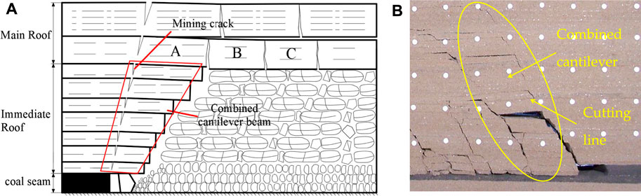
FIGURE 1. The combined cantilever beam structure in a fully-mechanized mining face: (A) roof structural model, (B) physical simulation result of roof cutting.
In addition to supporting the combined cantilever beam, the support also provides a certain support force for the articulated rock beam, so as to control the stability of the combined cantilever—articulated rock beam structure. When the support resistance is insufficient, it is difficult to prevent the excessive subsidence of the overlying roof, and the key block of the articulated rock beam will further sink. This forces the mining damaged area of the combined cantilever beam to expand, and then break and rotate. The rotating and sinking of the combined cantilever beam lead to the reduction of the support resistance acting on the articulated rock beam, which can easily to cause the sliding and instability of the articulated rock beam. This results in the large-scale roof cutting along the coal wall and the support crushing, thus forming the serious and violent strata behavior and the dynamic load impact phenomenon of the support. Therefore, ensuring the stability of combined cantilever beam and making the roof weighting behind the support is conducive to ensuring the safety and stability of the working face (Kong et al., 2010a; Kong et al., 2010b; Kong et al., 2010c; Li et al., 2014; Wang et al., 2014; Yang et al., 2016a; Li et al., 2017).
Currently, fracture mechanics research methods are increasingly being used in the study of coal mine disasters (Chen et al., 2011; Zhang et al., 2014; Yang et al., 2016b; Gao et al., 2017; Wang et al., 2018; Zhao et al., 2019; Wang et al., 2020; Yang et al., 2021). The roof structure model generally assumes that the rock stratum is a homogeneous and continuous medium, which is based on the basic theory and method of the theoretical mechanics or the material mechanics to analyze the stability and fracture of rock beam. However, after long-term tectonic activity and mining damage, there are inevitably some joints and fissures of different sizes, and even faults in the roof rock mass, which destroy the integrity and control the fracture and weighting of the roof. Therefore, each rock strata of the combined cantilever beam can be assumed as a cantilever beam with edge crack. The collapse criteria and supporting conditions of combined cantilever beam can be studied by the principle and method of fracture mechanics.
Therefore, based on the practice of fully mechanized mining of a large mining height, from the perspective of fracture mechanics, combined with the combined cantilever—articulated rock beam structure model, this paper studies the fracture evolution process and characteristics of combined cantilever beam, analyzes the fracture instability mechanical mechanism and its influence on the interaction between support and surrounding rock, and studies the determination method of support resistance.
To analyze the structural characteristics of overlying strata with large mining heights of shallow coal seam, we used the discrete-element numerical simulation software UDEC to construct a numerical model and analyzed the coal mining process with mining heights ranging from 3 to 7 m. The material model is calculated using the Mohr-Coulomb elastic–plastic theory model. The direction of the numerical model was 200 m, and the vertical height was 60 m. The upper boundary of the model was free. The bottom boundary, and the left-hand and right-hand horizontal boundary displacements were fixed.
The simulation results are shown in Figure 2. By comparing the roof fracture characteristics of 3–7 m mining height, it can be found that when the mining height is 3 and 4 m, the roof fracture conforms to the classical voussoir beam structure model (Figures 2A,B). When the mining height increases to 5 m, the rotation space of the roof increases. The roof collapses into the goaf, which makes the position of the voussoir beam structure move up, the thickness of the cantilever beam increases, and the rock beam has a certain scale of cutting (Figure 2C). When the mining height increases to 6 m, the rotation deformation increases after the roof is broken, and the maximum rotation angle reaches 52°, the thickness of cantilever beam increases continuously (Figure 2D). When the mining height increases to 7 m, the roof rotation deformation is greater, and the rotation angle reaches 60°. When the roof fractures, it is difficult to touch the gangue, the original rock strata with voussoir beam structure in small mining height cannot form an articulated structure but exists in the form of a cantilever beam. The fracture of the rock strata develops upward and the thickness increases until the upper strata form an effective support. Finally, the obvious combined cantilever-articulated rock beam structure is formed (Figures 2E,F). When the length of the rock beam exceeds a certain value, the roof of the combined cantilever beam will lose stability along the coal wall. The simulation results show that the greater the thickness of one-time mining in a fully mechanized face is, the easier it is to form a combined cantilever beam structure and the easier it is to lose stability.
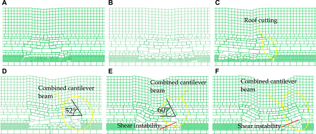
FIGURE 2. Overburden structure under weighting at different mining heights: (A) 3 m; (B) 4 m; (C) 5 m; (D) 6 m; (E) 7 m, first-weighting; (F) 7 m, periodic-weighting.
To analyze the formation process and fracture evolution law of a combined cantilever beam, and discuss the linkage mechanism between combined cantilever beam and overlying strata, I constructed a physical analysis model to simulate and analyze the weighting process of roof under the condition of 7 m mining height. In the physical model, the coal seam open-off cut was 25 cm away from the left-hand boundary, the excavation was from right-hand to left-hand, and was 5 cm each time.
The physical simulation results show that the large mining height increases the rotation space of the roof, the goaf cannot be filled in time after the working face is advanced (Figures 3A–C), the original rock strata that can form voussoir beam is transformed into cantilever beam with the original immediate roof, which increases the number of rock stratum and the thickness of cantilever beam (Figure 3D), Finally, the combined cantilever beam structure is formed (Figure 3E). The strata at higher position continue to collapse until the caving rock fills the goaf, forming a high voussoir beam structure, and the working face eventually forms a combined cantilever—articulated rock beam structure (Figure 3F). When the support resistance is insufficient, with the continuous advance of the working face, the articulated rock beam is unstable. This makes the rock strata of the combined cantilever beam rotate and deform. The damage edge crack of the cantilever beam then begins to expand, until the edge crack propagation and coalescence the rock stratum shear instability occurs (Figures 3B,C,G,H), and the combined cantilever beam cutting along the coal wall forms in a large range (Figure 3G). The interaction between the combined cantilever beam and articulated rock beam has formed the process of instability and weighting of the working face, the roof is cut off along the coal wall, and this results in the strata’s violent behavior. With the continuous advancement of the working face, the process of roof cutting along the coal wall caused by the instability of the combined cantilever beam continues to occur (Figures 3H,I), which creates a considerable hidden danger to the safe production of the working face.
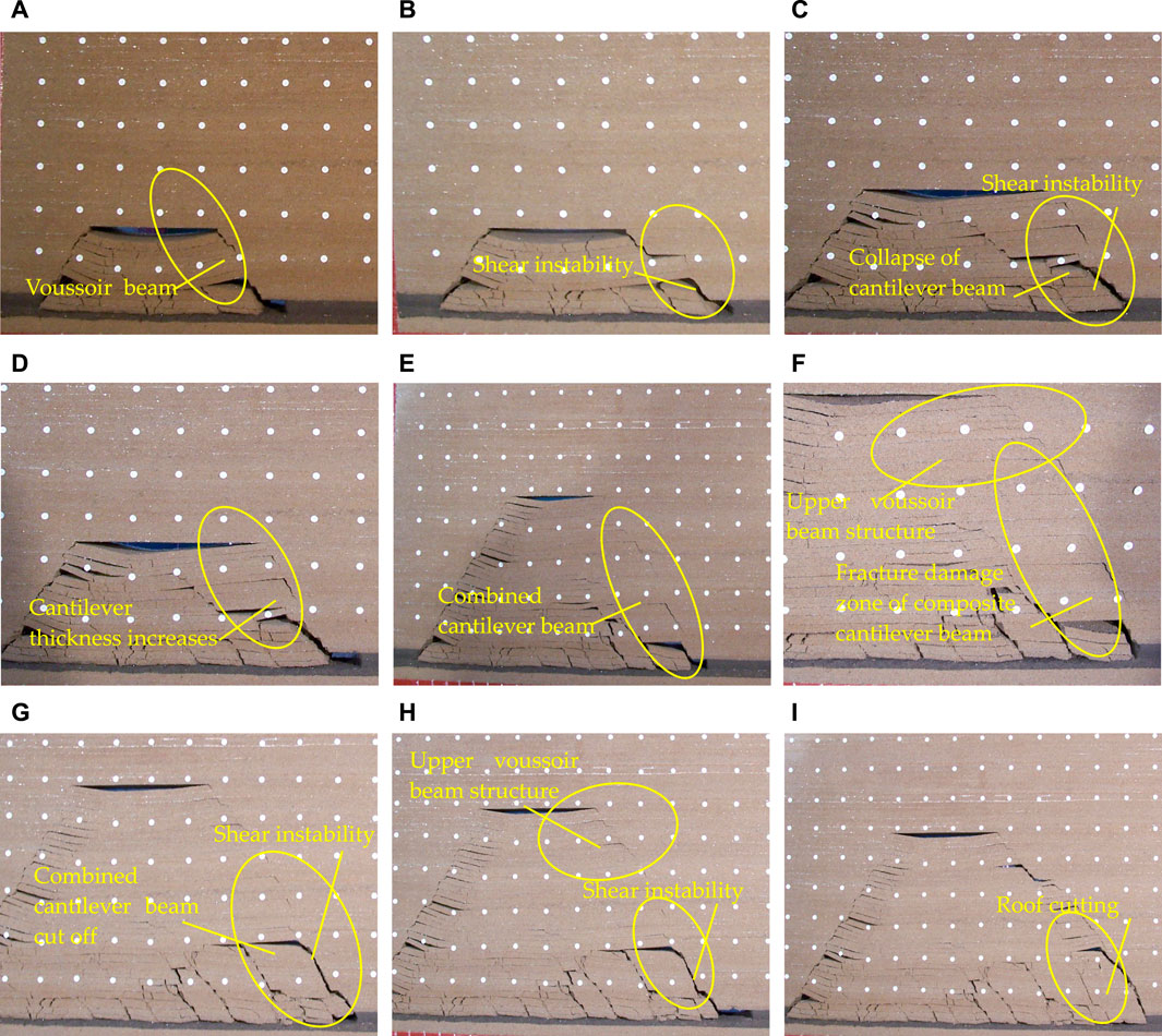
FIGURE 3. Simulation test results of similar materials.
Through simulation test analysis, it can be found that before the combined cantilever beam structure becomes unstable, the rock strata are not completely fractured but a cantilever beam with an edge crack can form. When the support capacity is insufficient, the combined cantilever beam structure rotation deforms, the crack starts to propagate and penetrate, it then forms a cutting line, which eventually leads to the instability along the coal wall of the combined cantilever beam shear structure, resulting in a large-area support crushing accident (Figure 3I). Therefore, in combination with specific engineering geological conditions, the rock strata of a combined cantilever beam are approximately a rock beam with an edge crack of arbitrary dip angle. We can then establish a fracture mechanics analysis model, and analyze the fracture and instability mechanism.
When the support resistance is insufficient, resulting in the sliding instability of the voussoir beam, and the voussoir beam acts on the combined cantilever beam, this can result in the fracture and collapse of the cantilever beam (Yan et al., 2015). The load of the support includes two parts: combined cantilever beam and articulated rock beam. The action of overlying strata on blocks A and B of the voussoir beam structure is set as the uniform load action ql. The load action of the voussoir beam structure on the lower support structure is analyzed by the model in (Yan, 2013). The model is shown in Figure 4.
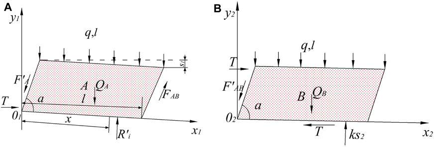
FIGURE 4. Force calculation of roof: (A) block A; (B) block B.
The load of voussoir beam can be expressed as (Yan et al., 2015):
where QA is the sum of the gravity of block A and the strata load controlled by it, kN; H and L are the thickness and weighting interval of “voussoir beam”, m; T is the horizontal stress, kN; α is the crack dip angle, (°); s1 is the subsidence of block A, m; FAB is the friction force between blocks A and B; QB is the sum of the gravity of block B and the strata load controlled by it, kN; K is the rigidity of gangue in goaf, kN/m; s2 is the compression of gangue in goaf (
The combined cantilever beam is cut by a set of structural planes inclined outward, and it controls the stability of rock beam (as shown in Figure 5A). Each rock stratum is horizontal, with a total height of h, the thickness of rock block is hi (i = 1, 2, ... , n), the length of structural plane is ai (i = 1, 2, ... , n), and the length of cantilever section is li (i = 1, 2,..., n) (Yan., 2015; Wang., 2020).
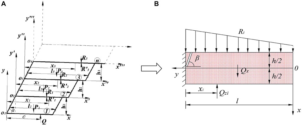
FIGURE 5. The construction of mechanical model: (A) force analysis of the model, (B) simplified mechanical analysis model of the ith cantilever beam.
To facilitate the calculation, according to the geometric characteristics of the combined cantilever beam structure, a simplified mechanical model is established to analyze the stress of the ith potential unstable rock beam. The analysis model is shown in Figure 5B. The loads on the model include the upper voussoir beam or cantilever beam structural load Ri and the lower support or cantilever beam supporting force QZi. Under the condition of large mining height, it is difficult for the beam-end gangue to form a supporting effect on the cantilever beam, so the supporting effect of gangue is not considered. Because the crack in the roof is usually a compound crack under complex loads, it is generally understood as a compression-shear crack. It is difficult to directly calculate the stress-intensity factor on the crack tip, so the cantilever beam rock stratum is regarded as a finite plate model with an oblique edge crack.
Since the combined cantilever beam is not subjected to horizontal stress, only the shear stress and bending moment are considered in the analysis of crack stress. The decomposed stress-intensity factor calculation models of the two simple loads are shown in Figure 6. The overburden load is decomposed into the concentrated force ql and bending moment M, the upper voussoir beam or cantilever beam structural load Ri, the gravity Qxi of the cantilever beam and the supporting force QZi of the lower rock beam or supports forms a shearing effect on the oblique edge cracks of the cantilever beam.
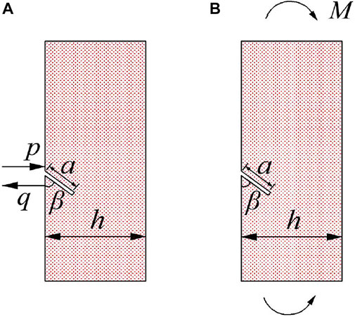
FIGURE 6. Stress-intensity factor calculation for two basic loads: (A) shear stress, (B) bending moment.
According to the equation of the finite plate model, the equation for calculating the stress-intensity factor under various simple loads is as follows (wang et al., 2020; Chinese Aeronautical Establishment, 1993):
(1) The calculation of the stress-intensity factor of the crack under the action of the shear stress (Figure 6A).
The shear force on the crack caused by the concentrated load of the roof, the gravity of the cantilever beam and the supporting force is simplified into the force model of the rock beam with oblique edge crack under uniaxial compression. The resultant shear force is
where Fτ can be obtained from the stress-intensity factor handbook.
(2) The calculation of the stress-intensity factor of the crack under the action of the bending moment (Figure 6B).
The bending stress of the rock beam is decomposed. The shear force obtained by decomposition counteracts each other and are omitted, only the stress-intensity factor under the action of σx is considered, where σx=6qL02 y/h3, y∈(-h/2, h/2).
where σ is the stress value of σx when y=h/2. Substituting
where FM can be obtained from the stress-intensity factor handbook.
The stress-intensity factor at the crack tip of the rock beam is the superposition of the stress-intensity factor under the above two simple loads, namely,
where Qxi is the gravity of the cantilever beam rock block of the ith layer; hi and li are the thickness and length of the cantilever beam rock block of the ith layer, m; β is the crack dip angle, (°); Ri is the additional load of the high rock strata, kN; and xi is the distance between the additional load Ri and the fracture point of the rock strata, m.
From Eq. 5, it can be found that the stress-intensity factor at the crack tip of cantilever beam is not only directly related to the length of the crack, the crack dip angle, and the thickness of the rock beam, but is also related to overlying strata load Ri, the weighting interval l of cantilever beam, and the supporting force Qzi. These factors determine the activation and propagation of the crack. With the increase of crack length a, KI and KII increase, which proves that the increase of crack length is more conducive to crack propagation. With the increase of the crack dip angle β, KI increase, KII increases first (0<β<45°) and then reduces (45<β<90°) with increasing of crack dip angle. When the thickness of the rock beam increases, KI decreases in the form of a negative third power function, while KII is unaffected. With the increase of overburden load Ri, the homogeneity of KI and KII increases, which indicates that the crack is easier to reach the fracture toughness of rock beam with the increase of overburden load, resulting in crack propagation, which is similar to the analysis conclusion of crack length a. With the increase of support force Qzi, KI and KII decrease, and the stability of rock beam increases. This indicates that the increase of support force is conducive to the stability of roof and the working face. These analysis results are consistent with the engineering practice, which verifies the correctness of the theoretical model.
According to a large number of experiments and field studies (Yu et al., 1991; Liu et al., 2008), the fracture criterion of rock and concrete materials can be expressed as follows:
where λ is the compression ratio of crack propagation, and KC is the fracture toughness of the rock.
By substituting Eq. 5 into Eq. 6, the fracture condition of the cantilever beam rock strata can be obtained as follows:
The key of the support controlling the stability of the overlying strata is to control the voussoir beam structure. The support not only provides the resistance of supporting the cantilever beam but also provides a certain supporting force for the voussoir beam structure, so as to control the stability of the combined cantilever - articulated rock beam structure.
From Eq. 7, the load force of the rock stratum on the next rock stratum can be obtained when any cantilever beam is instability, as follows:
The force of the ith cantilever beam in contact with the articulated rock beam on the i-1 stratum can then be expressed as:
By substituting Eq. 1 into Eq. 9, the supporting reaction force on the ith layer can be obtained:
Under the action of load, the uppermost rock stratum of combined cantilever beam is the first to lose stability. Through the iterative calculation of Eq. 9, the force Ri−1 of the i-1 rock stratum on the i-1 rock stratum can be obtained, which is the reaction force required for each stratum to maintain the limit equilibrium. The actual stability of each rock strata can be reflected by the size of Ri−1. In the same way, through iterative calculations, the force R1 of rock strata contacting with the support is the resistance value provided by the support for the first rock stratum. The stability of the combined cantilever beam can be judged by the iterative value R1 of the rock stratum (i.e., the support resistance), and the support resistance can be determined.
By iteration of Eq. 9, the equation for calculating the support resistance can be obtained (here xi=c):
where c is the distance between the action point of support force and the coal wall.
By analyzing the support resistance Eq. 13 calculated by the fracture mechanics method, it can be found that a fracture in the combined cantilever beam is unavoidable during the weighting process. If a reasonable support resistance is provided, then the stress environment is improved, and the combined cantilever beam will have a certain bearing effect. At the same time, the original immediate roof of the roof can maintain relatively good integrity due to the weakening of the upper load and maintain the safety of working face. Therefore, reasonable support resistance will weaken the appearance of strata behavior. However, when the support resistance is insufficient, it is easy to induce the expansion of the main control crack on the cantilever beam. Therefore, the support resistance is one of the necessary conditions for the edge crack propagation of the cantilever beam.
To thoroughly analyze the influencing factors of support resistance, we combined with the engineering geological conditions of the no. 22,310 coal mining face in the Daliuta mining area. According to the Eq. 11, the influence of rock thickness h, crack length a, weighting interval l, and crack dip angle β on support resistance were analyzed, as shown in Figure 7.
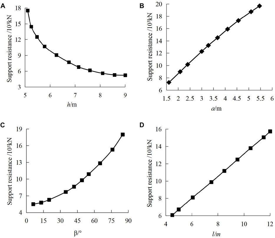
FIGURE 7. Support resistance calculation for three basic loads: (A) rock thickness, (B) crack length, (C) crack dip angle, and (D) weighting interval.
It can be found from the curves in Figure 7 that the support resistance has a curve decreasing relationship with the thickness of the cantilever beam h, a positive parabolic linear correlation with the crack length a, an approximately linear positive correlation with the cantilever beam weighting interval l, and a parabola with the crack dip angle β. With the increase of rock thickness, the difficulty of the roof collapse increases. The rotation angle decreases after the collapse, which reduces the force on the support. With the increase of crack dip angle β and crack length a, the support resistance increase. The main reason is that with the increase of crack angle and length, it is easier to meet the stress intensity factor conditions of crack propagation, and the crack initiation stress is reduced, so the main control crack is easy to expand and penetrate the cantilever beam structure. The influence of the crack length on the support resistance is realized through the roof fracture and instability (when a = h, the combined cantilever beam will cut directly along the coal wall). When the cantilever beam weighting interval l increases, the rock load acting on the support increases, and greater support resistance is needed to balance the overlying rock load. By comparing the four parameters, we find that the influence weight on the support resistance is as follows: crack length a > crack dip angle β > rock thickness h > weighting interval l.
Figure 8 shows a compression-shear crack model under complex load. The crack length is a, which is under the action of the maximum and minimum principal stresses σ1 and σ3. Because σn on the crack surface is a tensile stress, the crack propagation is the expansion of I and II compound cracks. Assuming that σ1 is the maximum compressive stress, the branch cracks generated during crack propagation will grow along the direction of the maximum compressive stress. When the crack propagation length of the airfoil branch crack reaches W (W=h−a) (i.e., the branch crack penetrates the rock strata) it will cause the rock fracture. Therefore, it is a sufficient condition for the cantilever beam to fracture and weighting when the branch fracture penetrates the cantilever beam or the propagation length reaches W.
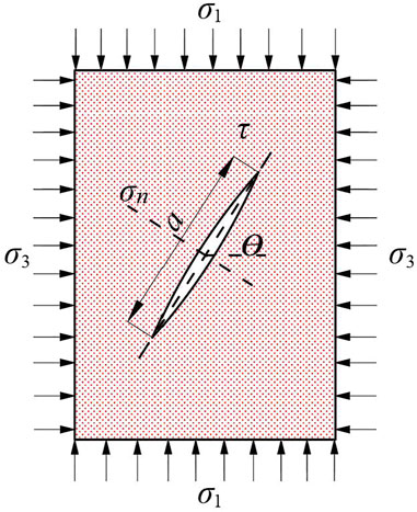
FIGURE 8. Compressive shear model of the crack.
The stress state on the crack surface can be expressed as:
where θ is the angle between the long axis direction of the crack and the minimum principal stress the direction of the crack.
The stress-intensity factor of the branch crack tip is composed of the stress-intensity factor (KI)1 generated by the shear stress on the crack surface and the stress-intensity factor (KI)2 produced by the far-field lateral stress σ3 (Chen, et al., 2011; Wang, et al., 2018).
where s is the length of the branch crack.
According to the principle of fracture mechanics, under the influence of mining stress, the lateral stress is a tensile stress in the fracture process of cantilever beam. Stress concentration and energy accumulation will occur at the tip of crack. The stress-intensity factor and crack length at the tip of branch crack will increase until the cantilever beam is penetrated. Under the action of lateral compressive stress, the stress-intensity factor KI of the branch crack tip decreases with the increase of the crack length, and the crack stops expanding When KI=KIc. Therefore, the length of the airfoil crack propagation can be expressed as:
The cantilever beam protection thickness W decreases with the accumulation of crack propagation length, when the crack propagation length s reaches W, it indicates that the crack penetrates through the cantilever beam, and the weighting occurs. This is a sufficient condition for the combined cantilever beam to fracture. It can be found from Eq. 14 that the length of the branch crack is proportional to the square of the stress-intensity factor at the crack tip and it is negatively related to the square of the resultant force on the crack surface. In other words, the lower the strength of the rock, the longer the length of the crack expansion, and the easier it is to penetrate the cantilever beam. According to the theory of elasticity, the stress-intensity factor increases much faster than the stress.
The Daliuta no. 22310 mining face is located in no.3 panel of 2−2 coal seam, with an average coal seam thickness of 7.55 m, and the dip angle of the coal seam is 1°–3°, the working face adopted domestic ZY16800/32/70 double column shield type hydraulic support, and the rated support resistance was 16,800 kN, the first weighting interval was 47.6 m, and the thickness of the coal seam was stable. The thickness of overlying bedrock was 125–300 m. The immediate roof was mainly composed of siltstone and sandy mudstone, and the floor was mainly composed of mudstone and siltstone. A comprehensive histogram is shown in Table 1.
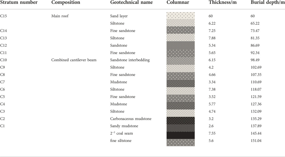
TABLE 1. Lithology of the no. 22310 working face.
The mining height of Daliuta no. 22310 fully mechanized mining face was 7.0 m, a total of 144 supports were installed on the mining face, taking the monitoring results of no.63 support as an example to analyze the characteristics of strata behavior. With the advance of the working face, periodic changes of one big and the other small for the weight interval and dynamic load coefficient in the working face were made. The specific roof weighing characteristic of the working face and the pressure curve of support no.63 are shown in Table 2; Figure 9. It can be found that the small periodic weighting interval is 9.1–10.8 m, with an average of 9.9 m, and the big periodic weighting interval is 11.9–16.1 m, with an average of 14.2 m. The small dynamic load coefficient is 1.34–1.41, with an average of 1.38, and the big dynamic load coefficient is 1.39–1.44, with an average of 1.4. The average support pressure is 16,037 kN, and the average continuous length is 4.0 m.
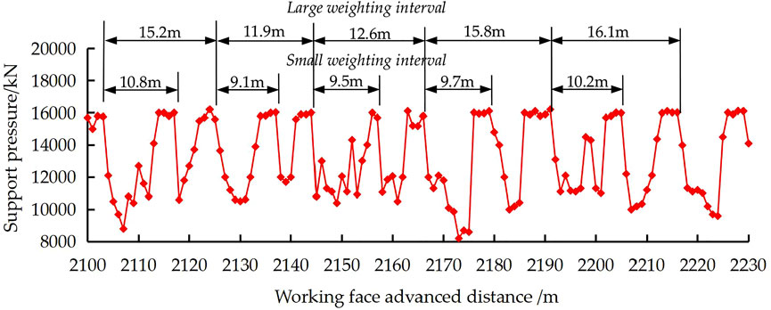
FIGURE 9. Resistance curve of no.63 support.
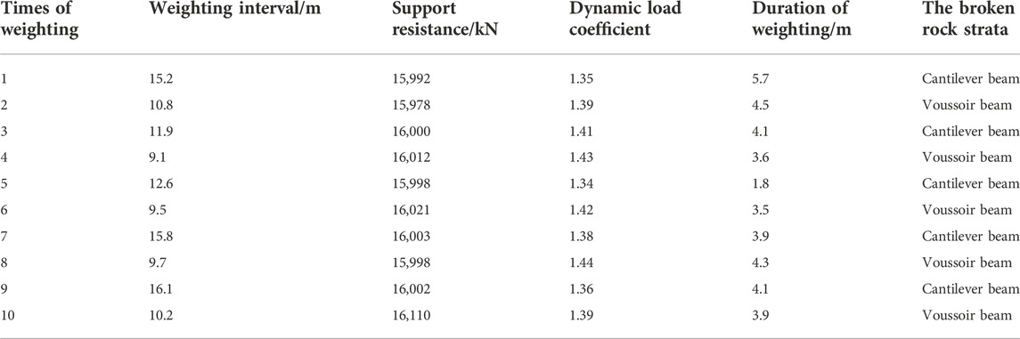
TABLE 2. The weighing characteristic of no.63 support.
From the comprehensive field monitoring data (Table 2; Figure 9), it can be found that the 9.9 m weighting interval of the working face corresponds to the instability of the voussoir beam structure, and the 14.2 m weighting interval corresponds to the instability of the lower cantilever beam structure. The instability ahead of time of the cantilever beam is caused by the instability of the voussoir beam, so the weighting interval of the voussoir beam is 14.2 + 9.9 = 24.1 m. Because of the bigger periodic weighting interval of the upper voussoir beam structure, the load applied to the support is also bigger, and so the corresponding dynamic load coefficient is also bigger. Finally, the periodic weighting interval and dynamic load coefficient (i.e., weighting intensity) of the working face show the phenomenon of alternating change, and the big weighting interval corresponds to the small dynamic load coefficient.
When the no. 22,310 fully mechanized mining face advances to 61.8 m, the first periodic weighting occurs. The large-scale roof weighting causes large-scale rib fall of the coal wall and serious end roof leakage. The rib fall depth was 1,250–1,470 mm (Figure 10A), and the height of the leaking gangue accumulation reached 3.4–4.8 m. During the period of weighting, the working face had obvious subsidence and obvious cracks on the surface, and the sinking amount was between 205 and 230 mm, with an average of 215 mm (Figure 10B). The support safety valve opened frequently and the roof sunk rapid, which presented a greater risk. Therefore, it was necessary to analyze the applicability of the hydraulic support with a rated working resistance of 16,800 kN.
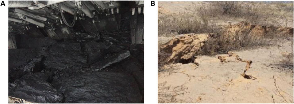
FIGURE 10. Roof disasters of no. 22,310 fully mechanized mining face: (A) rib fall of the coal wall, (B) step sinking of the ground.
Combined with the results of theoretical analysis, we analyzed the stability of the Daliuta coal mine no. 22,310 working face, the adaptability of support resistance was analyzed, and the rationality of theoretical analysis was verified. According to the actual mining conditions of the working face, the following parameters are determined: the support width is b=1.75 m, the top distance of the support control is lk=2.2 m, the length of the top support beam is 5.5 m, the distance from the coal wall to the centerline of the support column is 3.8 m, μ = 0.9, q = 1.12 MPa, RT = 3.7 MPa, σ1 = 0.73 MPa, σ3 = 0.32 MPa, λ = 1, Kc = 1.03 MN/m3/2, α = 35°, c = 3.5 m, λm=14.5 kN/m3.
According to the structural model of a cantilever beam-articulated rock beam, the roof rock stratum that satisfies Δji-Δmi ≤0 is the immediate roof, when Δji-Δmi ≥0, the rock stratum is the main roof, where Δji is the ultimate settlement (i=1, 2,···,13), Δmi is the possible subsidence (i=1, 2,···,13) (Yan, 2009; Yu, et al.,2012). The calculation method is as follows:
where H is the thickness of the rock stratum analyzed; K is the coefficient, k = 0.1 h; Q is the line load; l is the weighting interval of the analyzed strata; [σc] is the allowable compressive strength, [σc]=(0.30 ∼ 0.35)Rc, Rc is the compressive strength; p1 is the coal loss rate; hc is the mining height; hf is the drawing height; hf is the caving height; Kp is the bulking coefficient; and hm is the accumulated thickness of the immediate roof from the mth rock stratum.
The main roof and the immediate roof are judged according to the judgment criteria of the immediate roof strata.
Then, the C1-th rock stratum belongs to the immediate roof strata.
Then, the C2-th rock stratum belongs to the immediate roof strata.
We calculate and judge each rock stratum in turn, when i = 11,
It can be judged that the C11 and above rock strata are all main roof. The C1∼C10 strata will collapse into the goaf in the form of a combined cantilever beam.
Therefore, the stable state and weighting interval of the combined cantilever beam can be judged according to the theoretical analysis results, and the reasonable support resistance value can be discussed.
(1) Judgment of crack propagation and penetration
The stability judgment of the cantilever beam is calculated by taking the top ith rock stratum of the combined cantilever beam as an example.
The minimum safety thickness of C10 stratum is 6.85 m, which is more than 6.15 m, and meets the sufficient condition of a cantilever beam fracture. Under the current mining conditions, the rock strata will fracture and rotate, which further causes the lower rock strata to fracture, and forms the combined cantilever beam instability and support crushing.
(2) Calculation of the minimum support resistance
Continuously substituting from the ith rock stratum into the Eq. 12 for iterative calculations, the force R1 acting on the first rock stratum of the combined cantilever beam is 4,308 kN. The support resistance is calculated by substituting the R1 and the rock parameters into Eq. 11.
Based on the fracture mechanics analysis model of a combined cantilever beam, the insufficient support resistance in Daliuta no. 22,310 coal mine is the main cause of coal wall rib fall and ground subsidence. The reasonable support resistance is 17,752 kN through theoretical calculation. Therefore, it is necessary to increase the support resistance, optimize support parameters and performance to improve support strength, and reduce pressure and weighting intensity of fully-mechanized face to ensure the safe and efficient mining of the working face.
The 22,315 fully mechanized mining face is the replacement face of the 22,310 fully mechanized mining face, and the average thickness of the coal seam is 7.1 m. Combined with the above calculation results, the support strength of no. 22,315 working face is improved, and ZY19000/28/52 large mining height fully mechanized support is selected. The dynamic load coefficient of the no. 22,315 working face under big periodic weighting is shown in Table 3. The distribution curve of support resistance at no. 22,315 fully mechanized mining face is shown in Figure 11.
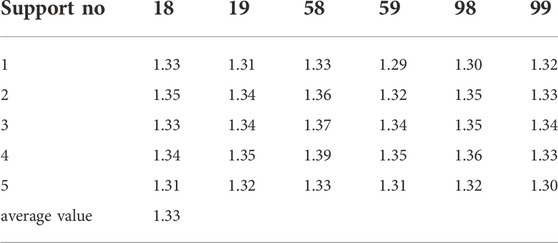
TABLE 3. Statistics of dynamic load coefficient in no. 22,315 working face under big periodic weighting.
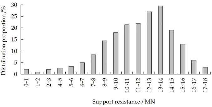
FIGURE 11. Support resistance distribution in a fully mechanized mining face.
The on-site strata behavior monitoring shows that the working face also has the phenomenon of large and small periodic weighting, and the average periodic weighting interval is 13.96 m, which is slightly smaller than that of no. 22,310 fully mechanized face. It can be found from Table 3 and on-site observations that the characteristics of strata behavior of no. 22,315 fully mechanized face are similar to those of no. 22,310 fully mechanized face, but the support adaptability is better and the dynamic load coefficient when roof weighting that is applied is much smaller than that of no. 22,310 working face (Figure 11). The roof is effectively controlled, and the weighting on the working face and the weighting intensity are alleviated. In the course of actual mining, there was no large-area roof cutting and support crushing accident.
To verify the rationality of the theoretical analysis results, the ground pressure measurement results of two fully mechanized mining faces with large mining height of 22,317 working face in Bulianta coal mine and 31,206 working face in Shigetai coal mine are compared with the 22,303 working face. Comprehensive histograms of the two working faces are given in Tables 4, 5.
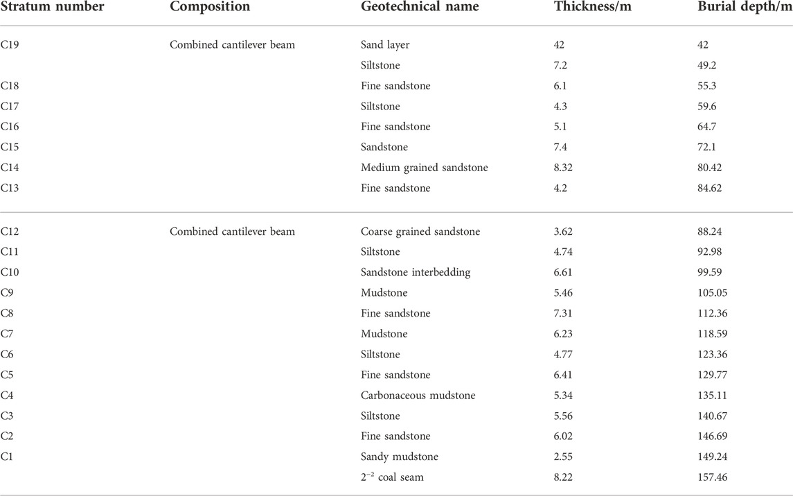
TABLE 4. Lithology of the no. 22,317 working face.
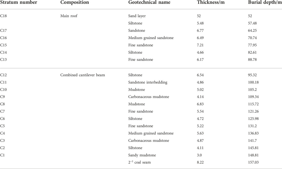
TABLE 5. Lithology of the no.60 support in 31,206 working face.
According to Eq. 15, the structural state of the roof formed by the weighting process of two fully mechanized face with large mining height is discriminated. It can be judged from the calculation results of each rock strata in two working faces that the C13 and above rock strata are all main roof, the C1∼C12 strata will collapse into the goaf in the form of a combined cantilever beam (the 22,317 working face), the C14 and above rock strata are all main roof, the C1∼C13 strata will collapse into the goaf in the form of a combined cantilever beam (the 22,317 working face). In Tables 6, 7, the dynamic load coefficient variation characteristics during the weighting process of the working face are counted, and it is also proved that the combined cantilever—articulated rock beam structure is formed when the roof is broken. Therefore, the reasonable support resistance value can be discussed according to the results of the theoretical analysis.

TABLE 6. The weighing characteristic of no.75 support in 22,317 working face.
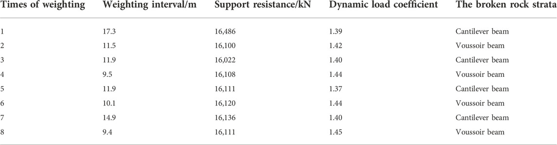
TABLE 7. The weighing characteristic of no.60 support in 31,206 working face.
The support resistance is calculated by substituting the rock parameters into Eq. 11. According to the calculation results, the reasonable support resistance is 17,131 kN in Shigetai no. 31206 coal mine, and the reasonable support resistance is 16,975 kN in Shigetai no. 31206 coal mine. Tables 5, 6 summarize the characteristics of strata behaviors of the two working faces. Comparing the theoretical calculation results, it can be found that the supports of the two working faces meet the production requirements.
In this paper, a mechanical model was developed to study the combined cantilever beam fracture mechanism based on the fracture mechanics theory, and the roof cutting instability mechanism with a large mining height face in a shallow coal seam was discussed. The calculation method of the support resistance to ensure the stability of working face were obtained, and the variation characteristics of the main control factors were analyzed. The validity of the theoretical analysis was verified with an engineering example. The following conclusions can be drawn through the analysis results:
(1) Comprehensive physical simulation and numerical analysis show that when the mining height of one-time mining in a fully mechanized face is larger, then the face will be more prone to instability of the combined cantilever beam. When the support resistance is insufficient, the rotation instability of the upper articulated rock beam causes the fracture instability of the combined cantilever beam.
(2) The fracture mechanics model of a combined cantilever beam was established, and the expressions of stress-intensity factor of cantilever beam breaking were derived. The calculation equations of the support resistance were deduced, the influence weights of each parameter on the support resistance are as follows: crack length a > crack dip angle β > rock thickness h > weighting interval l.
(3) When the crack propagation length s of the airfoil branch reaches the critical value W, the crack penetrates the cantilever beam. This is a sufficient condition for the cantilever beam to fracture. The insufficient support resistance causes the overlying strata to rotate and cause the crack propagation, which is one of the necessary conditions for the cantilever beam to fracture.
(4) The stability of the Daliuta no. 22,310 working face was analyzed using the theoretical analysis results. The results show that the working face meets the instability conditions, which was consistent with the monitoring results. The support resistance should be greater than 17,752 kN to ensure the stability of the combined cantilever—articulated rock beam, which is conducive to the support type that is chosen.
It should be pointed out that the instability criterion of the combined cantilever beam was derived by the fracture mechanics method. However, the research methods of rock material failure are complex and diverse, and the differences in the fracture characteristics of roof rock beams under different failure criteria need to be further studied. The composite cantilever beam is composed of multi-layer strata, including the key strata. However, whether or not its fracture motion forms as envisaged needs further verification.
At present, there is a lack of reasonable and effective research on the strata behavior mechanism of a shallow coal seam with a large mining height. This paper studies the fracture mechanism, support resistance, weighting interval, and other contents of the combined cantilever beam structure. This is helpful for the analysis and control of roof disasters in the process of weighting, has a certain guiding significance for the safety and stability of the working face, and is also conducive to reducing the occurrence of mining geohazards and eco-environmental issues, such as land subsidence, collapse, and water and soil loss.
The original contributions presented in the study are included in the article/supplementary material, further inquiries can be directed to the corresponding author.
YD: put forward the study ideas, YD: designed the article structure and wrote the paper, YD: conducted the theoretical derivation and analyzed the data, YD: collected and analyzed the data from mine site, YD: revised the English writing, YD: have read and agreed to the published version of the manuscript.
This research was funded by the National Natural Science Foundation of China (Grant no. 51704173), the Key R and D Projects of Shandong Province (Grant no. 2019GSF111029), the Science and Technology Program of Colleges and Universities in Shandong Province (Grant no. J17KA203), and the Qingdao Postdoctoral Researcher Application Research Project, and the open fund of Engineering Laboratory of Deep Mine Rockburst Disaster Assessment, Shandong Province (LMYK2021007).
The author declares that the research was conducted in the absence of any commercial or financial relationships that could be construed as a potential conflict of interest.
All claims expressed in this article are solely those of the authors and do not necessarily represent those of their affiliated organizations, or those of the publisher, the editors and the reviewers. Any product that may be evaluated in this article, or claim that may be made by its manufacturer, is not guaranteed or endorsed by the publisher.
QA, The sum of the gravity of block A and the strata load controlled by it; H and L, The thickness and weighting interval of “articulated rock beam”; T, The horizontal stress; a, The crack dip angle; s1, The subsidence of block A; FAB, The friction force between blocks A and B; QB, The sum of the gravity of block B and the strata load controlled by it; K, The rigidity of gangue in goaf; s2, The compression of gangue in goaf; kp1, The bulking coefficient of gangue; kp2, The residual swelling bulking coefficient of gangue; f, The friction coefficient between rock blocks; h, The total height of combined cantilever beam; hi, The thickness of rock block; ai, The length of structural plane; li, The length of cantilever section; Ri, The cantilever beam structural load; QZi, The lower support or cantilever beam supporting force; Qxi, The gravity of the antilever beam rock block of the ith layer; σ, the stress value of σx when y=h/2; β, The crack dip angle; RT, The ultimate tensile strength of rock; s, The length of the branch crack; Δmi, The possible subsidence; Δji, The ultimate settlement; W, The thickness of the analyzed rock stratum.
Chen, Z. H., Hu, Z. P., Li, H., and Chen, Q. F. (2011). Fracture mechanical model and criteria of insidious fault water inrush in coal mines. J. China Univ. Min. Technol. 40, 673–677.
Chinese Aeronautical Establishment (1993). Handbook of stress intensity factors. Beijing, China: Science Press, 320–321.
Feng, J. F., Zhou, Y., Zhang, K. Z., Jiang, D. J., and Liu, C. (2017). The influence of mining height increase on weighting intervals in the fully-mechanized panels of Shendong coal field. J. Min. Saf. Eng. 34, 632643–633636.
Feng, J. F., Zhou, Y., Zhang, K. Z., Xu, Y. L., and Li, H. G. (2018). Fracture characteristics of thick key stratum and calculation of shield work load under multiple coal seam mining gobs with shallow depth. J. Min. Saf. Eng. 35, 332–338. doi:10.13545/j.cnki.jmse.2018.02.014
Gao, M. S., Liu, Y. M., Zhao, Y. C., Gao, X. J., and Wen, Y. Y. (2017). Roof burst instability mechanism and dynamic characteristic of deep coal roadway subjected to rock burst. J. China Coal Soc. 42, 1650–1655.
Ghosh, G. K., and Sivakumar, C. (2018). Application of underground microseismic monitoring for ground failure and secure longwall coal mining operation: A case study in an Indian mine. J. Appl. Geophys. 150, 21–39. doi:10.1016/j.jappgeo.2018.01.004
Gong, P. L., and Jin, Z. M. (2008). Mechanical model study on roof control for fully-mechanized coal face with large mining height. Chin. J. Rock Mech. Eng. 27, 193–198.
Han, J., Zhang, H. W., Gao, Z. Y., Rong, H., Zhao, X. Z., Yang, F. W., et al. (2016). Failure height of weak overburden by layered fully-mechanized mining in extremely thick coal seam. J. Min. Saf. Eng. 33 (226–230), 237.
Huang, Q. X., Ma, L. T., Dong, B., and Shen, B. H. (2015). Research on equivalent immediate roof and roof structure of large mining height face. J. Xian Univ. Sci. Technol. 35, 541–546.
Huang, Q. X., and Tang, P. F. (2017). Roof structure analysis on large mining height longwall face in shallow coal seam. J. Min. Saf. Eng. 32, 187–191.
Ju, J. F., and Xu, J. L. (2015). Surface stepped subsidence related to top-coal caving longwall mining of extremely thick coal seam under shallow cover. Int. J. Rock Mech. Min. Sci. 78, 27–35. doi:10.1016/j.ijrmms.2015.05.003
Ju, J. F., Xu, J. L., and Wang, Q. X. (2011). Cantilever structure moving type of key strata and its influence on ground pressure in large mining height workface. J. China Coal Soc. 36, 2115–2120.
Kong, D. Z., Pu, S. J., Cheng, Z. H., Wu, G. Y., and Liu, Y. (2021). Coordinated deformation mechanism of the top coal and filling body of gob-side entry retaining in a fully mechanized caving face. Int. J. Geomech. 21 (4). doi:10.1061/(ASCE)GM.1943–5622.000197210.1061/(asce)gm.1943-5622.0001972
Kong, D. Z., Yang, S. L., Gao, L., and Ma, Z. Q. (2017). Determination of support capacity based on coal face stability control. J. China Coal Soc. 42, 590–596.
Kong, L. H., Jiang, F. X., and Liu, J. (2010b). Relationship between supportand strata in extra-thick coal seam fully-mechanized sublevel cavingmining based on high precision microseismic monitoring technology. Chin. J. Geotechnical Eng. 32, 401–407.
Kong, L. H., Jiang, F. X., and Wang, C. W. (2010c). Study of reasonable working resistance of support in fully-mechanized sublevel caving face in extra-thick coal seam. Chin. J. Rock Mech. Eng. 29, 2312–2318.
Kong, L. H., Jiang, F. X., Yang, S. H., Song, J. W., and Wang, C. W. (2010a). Movement of roof strata in extra-thick coal seams in top-coal caving mining based on a high precision micro-seismic monitoring system. J. Univ. Sci. Technol. Beijing 32, 552–558.
Li, H. M., Jiang, D. J., and Li, D. Y. (2014). Analysis of ground pressure and roof movement in fully-mechanized.top coal caving with large mining height in ultra-thick seam. J. China Coal Soc. 39, 1956–1960.
Li, H. M., Zhang, Q. L., Liu, C., Shen, L. l., and Li, H. G. (2017). Analysis on overburden strata movement and mine strata pressure behavior of high cutting mining in ultra thick seam. Coal Sci. Tech. 45, 27–33.
Li, Z., Xu, J. L., Yu, S. C., Ju, J. F., and Xu, J. M. (2018). Mechanism and prevention of a chock support failure in the longwall top-coal caving faces: A case study in datong coalfield. China. Int. J. energies. 288, 1–17.
Liang, Y. P., Li, B., Yuan, Y., Zou, Q. L., and Jia, L. X. (2017). Moving type of key strata and its influence on ground pressure in fully mechanized mining face with large mining height. J. China Coal Soc. 42, 1380–1391. doi:10.13225/j.cnki.Jccs.2016.1320
Liu, J. Y., Lin, G., Fan, L. S., Du, J. G., and Hu, Z. Q. (2008). The calculation of stress intensity factor including the effects of surface tractions. Chin. J. Comput. Mech. 25, 621–626.
Lou, J. F., Gao, F. Q., Yang, J. H., Ren, T. F., Li, J. Z., Wang, X. Q., et al. (2021). Characteristics of evolution of mining-induced stress field in the longwall panel: Insights from physical modeling. Int. J. Coal Sci. Technol. 8, 938–955. doi:10.1007/s40789-020-00390-5
Lou, J. F., Kang, H. P., Gao, F. Q., Yang, J. H., and Li, J. Z. (2017). Determination of largeheight support resistance based on multi-factor analysis. J. China Coal Soc. 42, 2808–2816. doi:10.13225/j.cnki.Jccs.2017.0695
Pang, Y. H., and Wang, G. F. (2017). Hydraulic support with large mining height structural optimal design and adaptability analysis. J. China Coal Soc. 42, 2518–2527. doi:10.13225/j.cnki.Jccs.2017.0233
Ren, Y, F., Ning, Y., and Xu, G. (2016). Dynamic interaction between support and roof in shallow coal seam. J. China Coal Soc. 41, 1905–1911. doi:10.13225/j.cnki.Jccs.2015.1771
Singh, G. S. P., and Singh, U. K. (2009). A numerical modeling approach for assessment of progressive caving of strata and performance of hydraulic powered support in longwall workings. Comput. Geotechnics 36, 1142–1156. doi:10.1016/j.compgeo.2009.05.001
Szurgacz, D., and Brodny, J. (2019a). Analysis of the influence of dynamic load on the work parameters of a powered roof support’s hydraulic leg. Sustainability 11, 2570. doi:10.3390/su11092570
Szurgacz, D., and Brodny, J. (2019b). Tests of geometry of the powered roof support section. Energies 12, 3945. doi:10.3390/en12203945
Wang, G. F., Pang, Y. H., Li, M. Z., Ma, Y., and Liu, X. H. (2017). Hydraulic support and coal wall coupling relationship in ultra large height mining face. J. China Coal Soc. 42, 518–526.
Wang, J. C., Yang, S. L., Li, Y., and Wang, Z. H. (2015). A dynamic method to determine the supports capacity in longwall coal mining. Int. J. Min. Reclam. Environ. 29, 277–288. doi:10.1080/17480930.2014.891694
Wang, J. C., and Wang, Z. H. (2015). Stability of main roof structure during the first weighting in shallow high-intensity mining face with thin bedrock. J. Min. Saf. Eng. 32, 175–181.
Wang, J. L., Yuan, Y., Tu, Shihao., and Li, B. (2014). Roof structure characteristics in fully mechanized coal face with large mining height and reasonable loading of support. J. Min. Saf. Eng. 31, 512–518.
Wang, J. M., Chen, Z. H., Zhang, L. F., Zhou, Z. H., Qian, F., and Zhou, H. J. (2020). Instability mechanism of counter-tilt layered rock slope by fracture mechanics analysis. Chin. J. Comput. Mech. 37, 75–82.
Wang, J. S., Yao, D. X., and Huang, H. (2018). Critical criterion and physical simulation research on progressive ascending water inrush in hidden faults of coal mines. J. China Coal Soc. 43, 2014–2020.
Wen, Z. J., Zhao, X. D., Yin, L. M., and Xia, H. C. (2010). Study on mechanical model and reasonable working-condition parameters in mining stope with large mining height. J. Min. Saf. Eng. 27, 255–258.
Xu, G., Zhang, Z., Yang, J. Z., Liu, Q. J., Fan, Z. Z., and Z, L, J. (2022). Interaction between support and surrounding rock in 8.8m super mining height working face. J. China Coal Soc. 47, 1462–1472. doi:10.13225/j.cnki,jccs.2021.0080
Xu, J. L., and Ju, J. F. (2011). Structural morphology of key stratum and its influence on strata behaviors in fully-mechanized face with super-large mining height. Chin. J. Rock Mech. Eng. 30, 1547–1556.
Xu, Y. J., and Fu, Z. P. (2021). Instability mechanism of rib in high:strength mining face beside gob with thick coal seam. Coal Sci. Technol. 12, 75–81.
Yan, S. H. (2013). New consideration of mine strata pressure behavior law and relationship between hydraulic powered support and surrounding rock in fully-mechanized top coal caving mining. Coal Sci. Technol. 41, 96–99.
Yan, S. H. (2009). Theory study on the load on support of long wall with top coal caving with great mining height in extra thick coal seam. J. China Coal Soc. 5, 590–593.
Yan, S. H., Xu, G., Zhang, X. L., and Zhang, Z. (2015). Reason analyses on large area roof cutting and collapse of hydraulic supports at fully-mechanized top coal caving mining face in ultra thick coal seams. J. Coal Sci. Technol. 43 (14–18), 140.
Yan, S. H., Yin, X. W., Xu, H. J., Xu, G., Liu, Q. M., and Yu, L. (2011). Roof structure of short cantilever-articulated rock beam and calculation of support resistance in full-mechanized face with large mining height. J. China Coal Soc. 36, 1816–1820.
Yang, D. F. (2021). Analysis of fracture mechanics theory of the first fracture mechanism of main roof and support resistance with large mining height in a shallow coal seam. Sustainability 13 (4), 1678. doi:10.3390/su13041678
Yang, D. F., Chen, Z. H., Hong, Q. F., and Zhang, S. S. (2016a). Catastrophic analysis of support crushing disasters while roof cutting in shallow seam mining. J. Min. Saf. Eng. 33 (122–127), 133.
Yang, D. F., Zhang, L. F., Chai, M., Li, B., and Bai, Y. F. (2016b). Study of roof breaking law of fully mechanized top coal caving mining in ultra-thick coal seam based on fracture mechanics. Rock Soil Mech. 37, 2034–2039.
Yang, D. F., Zhang, Y. J., and Chen, Z. H. (2020). Analysis on catastrophe theory during first weighting sliding instability and support crushing of main roof with large mining height in shallow coal seam. Appl. Sci. (Basel). 10, 5408. doi:10.3390/app10165408
Yang, J. Z., Liu, Q. J., Xu, G., and Zhang, Z. (2021). Strata behavior regularity and overlying strata broken structure of super large mining-height working face with 8.8 m support. J. Min. Saf. Eng. doi:10.13545/j.cnki.jmse.2020.0083
Yi, T., Han, X., Weitao, Y., Wenbing, G., Erhu, B., Tingye, Q., et al. (2022). Study on the overburden failure law of high-intensity mining in gully areas with exposed bedrock. Front. Earth Sci. 10, 833384. doi:10.3389/feart.2022.833384
Yin, X, W. (2017). Double period dynamic mechanism of support and surrounding rock in fully mechanized mining face. J. China Coal Soc. 42, 3072–3080. doi:10.13225/j.cnki.Jccs.2017.1297
Yin, X. W. (2019). Cutting block structure model of overburden with shallow buried coal seam and ultra-large mining height working face. J. China Coal Soc. 44, 1961–1970. doi:10.13225/j.Cnki.Jccs.2019.0375
Yu, B., Zhao, J., Kuang, T. J., and Meng, X. B. (2015). In situ investigations into overburden failures of a super-thick coal seam for longwall top coal caving. Int. J. Rock Mech. Min. Sci. 78, 155–162. doi:10.1016/j.ijrmms.2015.05.009
Yu, B., Zhu, W. B., Gao, R., and Liu, J. R. (2016). Strata structure and its effect mechanism of large space stope for fully-mechanized sublevel caving mining of extremely thick coal seam. J. China Coal Soc. 41, 571–580.
Yu, L., Yan, S. H., and Liu, Q. M. (2012). Determination of support working resistance of top coal caving in extra thick coal seam. J. China Coal Soc. 37, 737–742.
Yu, L., and Yan, S. H. (2015). Roof structure moving type and its influence on ground pressure of top coal caving in extra thick coal seam. Coal Sci. Technol. 43 (40–44), 59.
Yu, X. Z., Qiao, C. X., and Zhou, L. Q. (1991). Rock and concrete fracture mechanics. Changsha, China: Central South University of Technology Press, 230–278.
Zhang, J. G., Miao, X. X., Huang, Y. L., and Li, M. (2014). Fracture mechanics model of fully mechanized top coal caving of shallow coal seams and its application. Int. J. Min. Sci. Technol. 24, 349–352. doi:10.1016/j.ijmst.2014.03.011
Zhao, J. W., Zhou, H. W., Xue, D. J., Su, T., Deng, H. L., and Yang, H. Z. (2019). Expansion law of seepage path in the concealed structural floor of coal seam in deep confined water. J. China Coal Soc. 44, 1836–1845.
Zhao, Y. X., Ling, C. W., Liu, B., and He, X. (2021). Fracture evolution and energy dissipation of overlying strata in shallow-buried underground mining with ultra-high working face. J. Min. Saf. Eng. 38 (9–18), 30.
Keywords: large mining height, combined cantilever beam, stress-intensity factor, roof cutting, support resistance
Citation: Yang D (2023) Analysis on fracture mechanics theory of roof cutting instability mechanism with large mining height face in shallow coal seam. Front. Earth Sci. 10:900144. doi: 10.3389/feart.2022.900144
Received: 16 May 2022; Accepted: 01 July 2022;
Published: 11 January 2023.
Edited by:
Candan Gokceoglu, Hacettepe University, TurkeyReviewed by:
Ilie Onica, Universitatea Din Petrosani, RomaniaCopyright © 2023 Yang. This is an open-access article distributed under the terms of the Creative Commons Attribution License (CC BY). The use, distribution or reproduction in other forums is permitted, provided the original author(s) and the copyright owner(s) are credited and that the original publication in this journal is cited, in accordance with accepted academic practice. No use, distribution or reproduction is permitted which does not comply with these terms.
*Correspondence: Dengfeng Yang, eWFuZ19kZW5nZmVuZ0BxdXQuZWR1LmNu
Disclaimer: All claims expressed in this article are solely those of the authors and do not necessarily represent those of their affiliated organizations, or those of the publisher, the editors and the reviewers. Any product that may be evaluated in this article or claim that may be made by its manufacturer is not guaranteed or endorsed by the publisher.
Research integrity at Frontiers
Learn more about the work of our research integrity team to safeguard the quality of each article we publish.