 Dongdong Pang
 Kai He
 Yatao Xu3
95% of researchers rate our articles as excellent or good
Learn more about the work of our research integrity team to safeguard the quality of each article we publish.
Find out more
ORIGINAL RESEARCH article
Front. Earth Sci. , 10 May 2022
Sec. Geohazards and Georisks
Volume 10 - 2022 | https://doi.org/10.3389/feart.2022.885681
This article is part of the Research Topic Deep Rock Mass Engineering: Excavation, Monitoring, and Control View all 22 articles
To study the evolution law of axial force and shear stress of a full-length anchorage bolt in a rectangular roadway during roadway driving and working face mining, based on the stress analysis of the bolt, considering the elastic parameters and geometric size of the bolt, the effect of a bearing plate on surrounding rock, roadway cross-section shape, roadway deformation degree, and roadway elastic parameters, elastic mechanics and mathematical analysis methods were used to establish the mechanical model describing the interaction between the bolt and surrounding rock, and the mechanical formulas for calculating the axial force and shear stress of the bolt were derived. Taking the mining roadway of 1,131(1) working face in the Zhujidong coal mine of the Huainan mining area as the engineering background, the axial force and shear stress of the bolt in the middle of the roof and side of the rectangular roadway with the advance of driving face and working face were analyzed. The mechanical model and theoretical analysis results are verified by installing force measuring bolts with the same mechanical properties as the field and observing the real axial force distribution of the bolts.
The rectangular roadway has been widely used in coal mining roadways because of its advantages of fast driving speed and convenient construction. A rectangular roadway with bolts and cable support has become the most important design scheme for the coal mining roadway. With the continuous increase of coal mining depth, the support strength of mining roadways continues to improve. The full-length anchoring bolt can not only provide the surface force but also effectively prevent the deformation of the shallow surrounding rock of the roadway, which has become a powerful measure to improve the support strength. However, because of the complexity of the surrounding rock stress distribution of a rectangular roadway, the stress of its full-length anchoring bolt is obviously different from that of regular section roadways such as circular, oval, and straight wall semicircular arch, which has attracted the attention of many coal mine engineers and technicians (Lv et al., 2018; Mei et al., 2020).
Many scholars at home and abroad have carried out significant research on the mechanical properties of full-length anchoring bolts through theoretical analysis, numerical simulation, laboratory tests, or field tests. Wang et al. established the dynamic response model of full-length anchorage bolts. Based on structural dynamics and the explosion spherical wave theory, they calculated and analyzed the variation characteristics and distribution law of axial stress and shear stress of bolts with time under a blasting dynamic load (Wang et al., 2018; Zou and Zhang, 2021). Wang et al. systematically studied the mechanical characteristics of the full-length anchorage bolt under different working conditions, developed the anchor algorithm, carried out numerical tests, and analyzed the effects of continuous deformation magnitude, crack parameters, and confining pressure-drawing conditions on the distribution of the axial force and shear stress of the full-length anchoring bolt. Li et al., based on the deformation of the surrounding rock, established the bolt-surrounding rock interaction model, and deduced the analytical expressions of the distribution of axial force and shear stress along the bolt body during the normal support process and critical failure of the bolt (Wu et al., 2018; Zhao et al., 2020). Chang et al. proposed a simplified method to analyze the interaction between full-length anchoring bolts and rock mass in circular roadways under hydrostatic stress field. In this process, the relative motion between the rock mass and bolt is determined by considering the interfacial shear stiffness. In addition, the elastic elongation of the bolt is also considered. The rock bolt interaction is simulated in the initial and final states (Cheng et al., 2015; Chang et al., 2019). Zhou et al. proposed a numerical model based on the double exponential curve shear slip-model of the anchorage interface and the linear strengthened elastoplastic constitutive model of the bolt, and verified the model through the pull-out test (Cui et al., 2021). Chen et al. established an analytical model to study the load transfer characteristics of the full-length anchoring bolt and verified the theoretical model by the field pull-out test. It is found that the axial load of the bolt attenuates from the loading end to the free end, which is independent of the pull-out load (Chen et al., 2020). Zou et al. proposed a dynamic bond-slip model to describe the dynamic evolution characteristics of the bond strength of the bolt rock interface, and deduced the analytical solutions of the shear stress distribution, load-displacement relationship, and relative displacement of the bolt considering the free end slip (Jin-feng and Peng-hao, 2019). Aghchai et al. studied the interaction between the full-length anchoring bolt and slurry and the surrounding rock in the pull-out test, considered different stages such as complete bonding and partial anchoring, and analyzed and obtained the load-displacement curve of the anchor head (Aghchai et al., 2020). Liu et al. considered the combined action of axial force and shear force of the bolt, and proposed an improved prediction method for the shear strength contribution of full-length anchoring bolts (Liu and Li, 2020). Liu et al. established the analytical model of the interaction between the bolt and surrounding rock, deduced the control differential equation of load transfer, obtained the stress distribution of the anchor body, and proposed the calculation method of the bolt considering the shear damage of the anchorage interface based on the finite element method (Liu et al., 2017; Lyu et al., 2018). Liu and Li analyzed the load distribution and deformation characteristics of the deflection section of the full-length anchoring bolt, and established the structural mechanics model. Based on the force method equation and deformation coordination relationship, the analysis method of the influence of axial force and shear force at the intersection of the bolt and joint surface on the stability of the rock slope is established, and the influence of bolt inclination on the joint surface is discussed (Liu and Li, 2017; Li and Liu, 2019). There are many similar research results, such as those achieved by Liu et al., (2017) and Sun et al. (2021). Although the existing studies have carried out detailed research on the mechanical properties of full-length anchoring bolts and have achieved rich research results, the existing research methods seldom consider the influence of the roadway section shape and roadway surrounding rock deformation characteristics on the full-length anchoring bolt. This leads to many conclusions which cannot be directly applied to production practice.
To sum up, this study refers to the existing research results, fully considers the section shape of the mining roadway and the deformation of the surrounding rock of the mining roadway, establishes and solves the mechanical model of the bolt through the stress analysis of the bolt, and deduces the mechanical formula for calculating the axial force and shear stress of the bolt. Based on the engineering background of 1,131(1) working face of the Zhujidong coal mine in the Huainan mining area, the variation law of axial force and shear stress of full-length anchoring bolts in the middle of the roof and side of a rectangular roadway with the advance of the driving face is analyzed. The change of axial force of full-length anchoring bolts during roadway driving is observed by the force measuring bolt, which verifies the correctness of theoretical analyses. It provides a theoretical basis for bolt support design.
It is assumed that the surrounding rock is an isotropic elastomer without considering the influence of an anchoring agent. At the same time, it is assumed that the bolt is a one-dimensional elastomer without considering the transverse deformation of the bolt. It is assumed that the stress and displacement of the bolt are continuous at the anchorage surface. The coordinate system is established as shown in Figure 1, and mechanical model is obtained for calculating the axial force and shear stress of the bolt by analyzing the stress of the bolt and deformation of the surrounding rock.
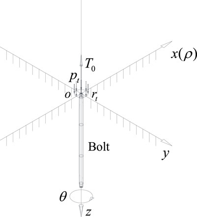
FIGURE 1. Stress diagram of the bolt and surrounding rock.
In Figure 1,
The stress of the bolt is shown in Figure 2.
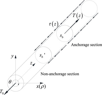
FIGURE 2. Bolt stress diagram.
The bolt body from the end of the anchor to the section
In Eq. 1,
According to the field observation data and the design requirements of the bolt support, the bolts are in the elastic state during roadway driving. Therefore, the relationship between the axial normal stress
In Eq. 3, E represents the elastic modulus of the bolt. Substituting Eq. 3 into Eq. 2, we can get
By substituting Eq. 4 into Eq. 1, the relationship between the bolt surface shear stress
The shear stress and strain of the surrounding rock at the anchorage surface are the same as the shear stress and axial strain of the bolt. Then, the shear stress and strain of the surrounding rock at the anchorage surface can be substituted into Eq. 5. By solving Eq. 5, the expressions of axial force and shear stress of the bolt are derived.
Assuming that the extrusion force of the bearing plate on the surrounding rock is uniformly distributed and there is no shear load on the surrounding rock, the force of the bearing plate on the surrounding rock is shown in Figure 3:
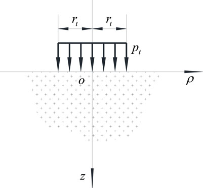
FIGURE 3. Force of the bearing plate on the rock wall.
In Figure 3, the calculation method of
In Eq. 6,
In Eq. 7,
In Eq. 8,
By substituting the Love displacement function Eq. 7 into Eq. 9, the displacement distribution law of the surrounding rock when it is squeezed by the bearing plate can be obtained.
In Eq. 9,
Assuming that the stress distribution of roadway surrounding rock is a plane strain problem, the proposed complex function method is used to solve the strain distribution law of rectangular roadways (Muskhelishvili and Noordhoff, 1953; Feng et al., 2014; Tran Manh et al., 2015; Shen et al., 2017; Chang et al., 2020). The stress of a rectangular roadway is shown in Figure 4.
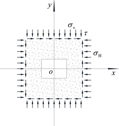
FIGURE 4. Stress diagram of the rectangular roadway.
The stress distribution of the surrounding rock of a rectangular roadway can be characterized by two complex functions
In Eq. 10, the function
In Eq. 11,
In Eq. 12,
The load function
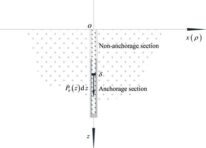
FIGURE 5. Schematic diagram of
Take microelements on the bolt for analysis. At this time, the surrounding rock
In Eq. 13, the function
In Eq. 14,
Integrate Eq. 13 on the bolt body to obtain the Love displacement function:
Through Eq. 16, the effect of the distribution load
In Eq. 17, the sum of tensors
According to the uniqueness theorem of solution in elasticity, there is only one exact solution satisfying the corresponding boundary conditions. The contact surface between the bolt and the surrounding rock can be regarded as a boundary condition. When the surrounding rock is taken as the research object, it has two boundaries. The first is the free surface of the surrounding rock and the second is the contact surface between the bolt and the surrounding rock, that is, the anchorage surface. When the two boundary conditions are consistent, the stress-strain state in the surrounding rock is unique and determined. The boundary condition of the surrounding rock at the free surface is not affected by the bolt. When the anchorage surface does not slide, the stress and strain are continuous on the anchorage surface. The stress and strain on the anchorage surface meet both the mechanical equation of the surrounding rock and the mechanical equation of the bolt. Therefore, the stress and strain of the surrounding rock at the anchorage surface can be substituted into the mechanical equation of the bolt, and the functional equation with the distributed load function
Substituting the values of stress and strain at the anchorage surface into Eq. 5, we can get
In Eq. 18,
Substitute Eq. 17 into Eq. 18 and simplify it to obtain
Eq. 20 is the first kind of Fredholm integral equation (Mesgarani and Azari, 2019; Khan et al., 2020), in which the function
According to the relevant theory of integral equation, the outgoing load function
Substituting Eq. 22 into Eq. 1, and then differentiating and sorting Eq. 1, the expression of the surface shear stress
By substituting the stress variables of the surrounding rock under different engineering conditions into Eq. 18, the distribution curves of the bolt axial force and shear stress under the corresponding engineering conditions can be obtained.
The schematic diagram of a driving roadway is shown in Figure 6. When the roadheader cuts out the complete roadway section, some bolts are installed immediately to support the roadway, and its position is shown at point A of Figure 6. At this time, the surrounding rock is supported by the front coal wall without deformation or the deformation is very small, which can be ignored compared with the deformation of the surrounding rock in the later stage. When it is far away from the coal wall, as shown at point B, the bolt is affected by the deformation of the surrounding rock and the axial force of the bolt changes (Chang et al., 2021).
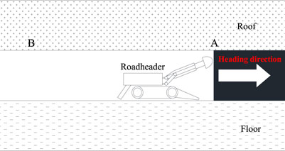
FIGURE 6. Schematic diagram of the driving roadway.
In Eq. 24, the parameter a1 reflects the severity of the surrounding rock deformation within the influence range of the driving face; l represents the distance between the bolt and the working face;
In Eq. 25, function H( ) represents the Heaviside step function; l represents the distance from the working face;
Based on the engineering background of 1,131(1) working face of the Zhujidong coal mine in the Huainan mining area, the distribution law of the axial force and shear stress of full-length anchoring bolts in a rectangular roadway during driving is studied. The mining roadway of 1,131(1) working face has a width of 5.2 m and a height of 3.2 m, which is supported by the bolt and a cable. The bolt support parameters are shown in Table 1 and the roadway section and support structure are shown in Figure 7.
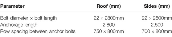
TABLE 1. Bolt support parameters.
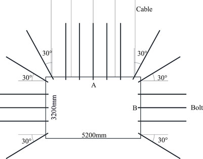
FIGURE 7. Schematic diagram of the roadway support scheme.
The roof and floor of 1,131(1) working face are mudstone, which is similar to the mechanical properties of a coal seam and can be combined. Through the measurement test of rock mechanical parameters, the shear modulus G of the surrounding rock is 1.72 GPa and Poisson’s ratio v is 0.21. According to the tensile test results of a bolt, the elastic modulus E of the bolt is 203 GPa. According to the in-situ stress test results, the vertical pressure of the roadway
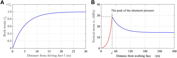
FIGURE 8. Influence of mining stress: (A) variation curve of the surrounding rock strain with an advance of the driving face; and (B) the abutment pressure curve.
Taking bolts A and B in the middle of the roof and side as examples, the evolution law of the axial force and shear stress of full-length anchoring bolts during driving roadway is studied. To verify the theoretical analysis results, during roadway driving, some force measuring bolts with the same mechanical parameters and geometric dimensions as the on-site bolts are used to replace bolts A and B to observe the axial force distribution of bolts. The force measuring bolt is shown in Figure 9A and the force measuring bolt installed on site is shown in Figure 9B.
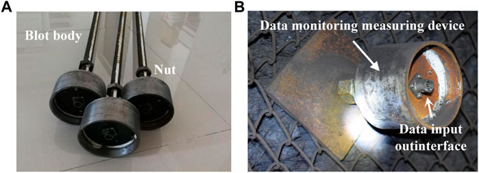
FIGURE 9. Force measuring bolt: (A) force measuring bolt in the laboratory; and (B) force measuring bolt installed on site.
Six groups of axial force-monitoring points are arranged on each force measuring bolt and the distance between each group of axial force-monitoring points and the bearing plate is shown in Table 2.

TABLE 2. Location of measuring points.
By substituting the relevant data into the bolt mechanical model, the variation curve of the axial force of a full-length anchoring bolt in a rectangular roadway during roadway driving and working face mining can be obtained. The variation curve of the axial force of the bolts A and B with the advance of driving face and working face is shown in Figure 10.
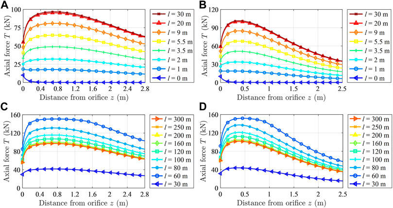
FIGURE 10. Distribution law of the axial force of the bolt with the bolt body: (A) Variation law of the axial force of bolt A with the advance of the driving face; (B) Variation law of the axial force of bolt B with the advance of the driving face; (C) Variation law of the axial force of bolt A with the advance of the working face; and (D) variation law of the axial force of bolt B with the advance of the working face.
It can be seen from Figure 10 that for the full-length anchoring bolt in the middle of the roof and side of the rectangular roadway, the distribution law of its axial force along the bolt body direction is roughly the same. With the advance of the driving face, the axial force rapidly evolves from a monotonous decreasing trend to the change law of first increasing and then decreasing. But with the advance of the working face, the axial force increases first and then decreases. The axial force change of the bolt in the middle of the roof is gentler than that in the middle of the side. The maximum axial force point of the bolt quickly stabilizes at the neutral point from the orifice position with the advance of the driving face. The neutral point of the bolt in the middle of the roof is 0.75 m away from the orifice, and the neutral point of the bolt in the middle of the side is 0.40 m away from the orifice. The neutral point of the bolt on the roadway side is closer to the roadway surface. The working resistance of the bolt shows a monotonous increasing trend with the advance of the driving face and the working face.
According to Eq. 23, the distribution curve of the shear stress of the bolt body can be obtained. The evolution curve of the shear stress of the bolt body with the advance of the driving face and the working face is shown in Figure 11. In Figure 11, the sub coordinate system is a local magnification of the main coordinate system.
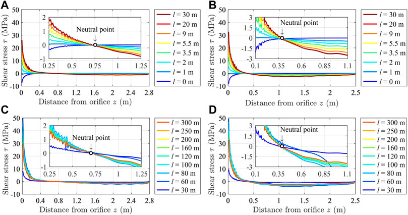
FIGURE 11. Distribution law of the shear stress of the bolt with the bolt body: (A) Variation law of the shear stress of bolt A with the advance of the driving face; (B) Variation law of the shear stress of bolt B with the advance of the driving face; (C) the variation law of the shear stress of bolt A with the advance of the working face; and (D) variation law of the shear stress of bolt B with the advance of the working face.
It can be seen from Figure 11 that the evolution law of the shear stress in the middle of the roof and the bolt in the middle of the side is the same with the advance of the driving face and the working face. When there is no neutral point in the bolt, that is, when the bolt is installed in the surrounding rock, the shear stress of the bolt shows a monotonous increasing trend. When there is a neutral point in the bolt, that is, when the bolt is far away from the driving face, the shear stress of the bolt shows a monotonous decreasing trend. The variation range of the shear stress of the bolt in the middle of the side is greater than that of the bolt in the middle of the roof. The shear stress curve of the bolt intersects at one point, that is, the neutral point of the bolt, which indicates that the neutral point position of the bolt does not change during roadway driving and working face mining.
Comparing Figures 10, 11, it can be seen that when the shear stress of the bolt is less than 0, the axial force of the bolt decreases. When the shear stress of the bolt is greater than 0, the axial force of the bolt increases. On both sides of the neutral point of the bolt, the sign of the shear stress of the bolt is different, which is consistent with the neutral point theory.
The mining roadway of 1,131(1) working face is driving for 4.8 m every day. After installing the force measuring bolt, it is observed twice on the first day and once every day, after that, for a total of 7 days. The observed data are shown in Figure 12.
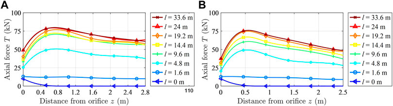
FIGURE 12. Variation curve of the axial force of a force measuring bolt: (A) Force measuring anchor bolt A in the middle of the roof and (B) force measuring anchor bolt B in the middle of the side.
It can be seen from Figure 12 that the axial force distribution law of the bolt measured by the force measuring bolt is basically consistent with the axial force distribution law obtained by theoretical calculations. When the force measuring bolt is installed into the surrounding rock, the axial force of the bolt shows a monotonous decreasing trend. When it is far from the driving face, the axial force of the bolt increases first and then decreases. The maximum value is reached at the neutral point of the bolt. The neutral point of the roof force measuring bolt is between 0.52 and 1.04 m. The neutral point of the side force measuring bolt is about 0.46 m, which is consistent with the theoretical calculation results. The variation range of the axial force of the force measuring bolt in the middle of the roadway side is greater than that of the force measuring bolt in the middle of the roof. The working resistance of the force measuring bolt in the middle of the roadway side is less than that of the force measuring bolt in the middle of the roof, which is consistent with the theoretical calculation results. The correctness of the theoretical calculation results can be verified from the observation data of the force measuring bolt.
To study the evolution law of the axial force and shear stress of full-length anchoring bolts in a rectangular roadway during roadway driving and working face mining, considering the deformation of the surrounding rock, the mechanical model of the bolt is established and solved through the stress analysis of the bolt. Then, the mechanical formulas for calculating the axial force and the shear stress of the bolt are deduced. Taking the mining roadway of 1,131(1) working face in the Zhujidong coal mine as the engineering background, the evolution law of the axial force and the shear stress of the full-length anchoring bolt in the middle of the roof and the side of the rectangular roadway with the advance of the driving and the working face are analyzed. The theoretical analysis results are verified by the observation data of the force measuring bolt. The axial force distribution law of the bolt in the middle of the roof and the bolt in the middle of the roadway side is the same. When the bolt is installed, the axial force of the bolt decreases monotonically along the direction of the bolt. The axial force of the bolt first increases and then decreases along the direction of the bolt, and the maximum value appears at the neutral point. The neutral point position remains unchanged. The distribution law of the shear stress of the bolt body in the middle of roof and side is the same. The shear stress of the bolt shows a monotonous increasing trend along the direction of the bolt. At different distances from the driving face or the working face, the shear stress of the bolt converges at the neutral point. The variation range of the shear stress of the bolt body in the middle of the roadway is greater than that of the bolt in the middle of the roof.
All claims expressed in this article are solely those of the authors and do not necessarily represent those of their affiliated organizations, or those of the publisher, the editors, and the reviewers. Any product that may be evaluated in this article, or claim that may be made by its manufacturer, is not guaranteed or endorsed by the publisher.
The original contributions presented in the study are included in the article/Supplementary Material; further inquiries can be directed to the corresponding author.
DP wrote the main manuscript text. KH and YX established and solved the theoretical mode. JC designed the experiments. XN and CL collected field test data. All authors reviewed the manuscript.
This work was supported by the National Natural Science Foundation of China (nos. 51774009, 52174103, and 52174105); Key Research and Development Projects in Anhui Province (No. 202004a07020045), and the Natural Science Foundation of Anhui Provincial Natural Science Foundation (No. 2008085ME147).
The authors declare that the research was conducted in the absence of any commercial or financial relationships that could be construed as a potential conflict of interest.
Aghchai, M. H., Maarefvand, P., and Salari Rad, H. (2020). Analytically Determining Bond Shear Strength of Fully Grouted Rock Bolt Based on Pullout Test Results. Period. Polytech. Civ. Eng. 64 (1), 212–222. doi:10.3311/PPci.15195
Baddoo, P. J., and Crowdy, D. G. (2019). Periodic Schwarz-Christoffel Mappings with Multiple Boundaries Per Period. Proc. R. Soc. A 475 (2228), 20190225. doi:10.1098/rspa.2019.0225
Badreddine, M., DeLillo, T. K., and Sahraei, S. (2019). A Comparison of Some Numerical Conformal Mapping Methods for Simply and Multiply Connected Domains[J]. Discrete Continuous Dyn. Syst. - Ser. B 24 (1), 5. doi:10.3934/dcdsb.2018100
Chang, C.-Y., Chang, E.-C., and Huang, C.-W. (2019). In Situ Diagnosis of Industrial Motors by Using Vision-Based Smart Sensing Technology. Sensors 19, 5340. doi:10.3390/s19245340
Chang, J., He, K., Pang, D., Li, D., Li, C., and Sun, B. (2021). Influence of Anchorage Length and Pretension on the Working Resistance of Rock Bolt Based on its Tensile Characteristics. Int. J. Coal Sci. Technol. 8 (6), 1384–1399. doi:10.1007/s40789-021-00459-9
Chang, J., He, K., Yin, Z., Li, W., Li, S., and Pang, D. (2020). Study on the Instability Characteristics and Bolt Support in Deep Mining Roadways Based on the Surrounding Rock Stability Index: Example of Pansan Coal Mine. Adv. Civ. Eng. 2020, 1–16. doi:10.1155/2020/8855335
Chen, J., He, F., and Zhang, S. (2020). A Study of the Load Transfer Behavior of Fully Grouted Rock Bolts with Analytical Modelling. Int. J. Min. Sci. Technol. 30 (1), 105–109. ISSN 2095-2686. doi:10.1016/j.ijmst.2019.12.010
Cheng, L., Zhang, Y., Ji, M., Cui, M., Zhang, K., and Zhang, M. (2015). Theoretical Calculation and Analysis on the Composite Rock-Bolt Bearing Structure in Burst-Prone Ground. Math. Problems Eng. 2015, 1–6. Article ID 434567. doi:10.1155/2015/434567
Cui, L., Sheng, Q., Dong, Y., Ruan, B., and Xu, D.-D. (2021). A Quantitative Analysis of the Effect of End Plate of Fully-Grouted Bolts on the Global Stability of Tunnel. Tunn. Undergr. Space Technol. 114, 104010–202110. ISSN 0886-7798. doi:10.1016/j.tust.2021.104010
Feng, Q., Jiang, B.-S., Zhang, Q., and Wang, L.-P. (2014). Analytical Elasto-Plastic Solution for Stress and Deformation of Surrounding Rock in Cold Region Tunnels. Cold Regions Sci. Technol. 108, 59–68. doi:10.1016/j.coldregions.2014.08.001
He, K., Chang, J., Pang, D., Sun, B., Yin, Z., and Li, D. (2022). Iterative Algorithm for the Conformal Mapping Function from the Exterior of a Roadway to the Interior of a Unit Circle. Arch. Appl. Mech. 92, 971–991. doi:10.1007/s00419-021-02087-w
Jin-feng, Z., and Peng-hao, Z. (2019). Analytical Model of Fully Grouted Bolts in Pull-Out Tests and In Situ Rock Masses. Int. J. Rock Mech. Min. Sci. 113, 278–294. ISSN 1365-1609,. doi:10.1016/j.ijrmms.2018.11.015
Khan, F., Arshad, T., Ghaffar, A., Sooppy Nisar, K., and Kumar, D. (2020). Numerical Solutions of 2D Fredholm Integral Equation of First Kind by Discretization Technique. AIMS Math. 5 (3), 2295–2306. doi:10.3934/math.2020152
Li, Y., and Liu, C. (2019). Experimental Study on the Shear Behavior of Fully Grouted Bolts. Constr. Build. Mater. 223, 1123–1134. ISSN 0950-0618. doi:10.1016/j.conbuildmat.2019.06.207
Liu, C. H., and Li, Y. Z. (2017). Analytical Study of the Mechanical Behavior of Fully Grouted Bolts in Bedding Rock Slopes. Rock Mech. Rock Eng. 50 (9), 2413–2423. doi:10.1007/s00603-017-1244-9
Liu, C., and Li, Y. (2020). Predicting the Shear Resistance Contribution of Passive Full-Length Anchoring Bolts to Jointed Rock[J]. Int. J. Geomechanics 20 (2), 1–11. doi:10.1061/(asce)gm.1943-5622.0001581
Liu, G., Xiao, M., Chen, J., and Zhou, H. (2017). Study on Mechanical Characteristics of Fully Grouted Rock Bolts for Underground Caverns under Seismic Loads[J]. Math. Problems Eng. 2017, 12. doi:10.1155/2017/1657369
Lv, Z., Qin, Q., Jiang, B., Luan, Y., and Yu, H. (2018). Comparative Study on the Mechanical Mechanism of Confined Concrete Supporting Arches in Underground Engineering. PLoS ONE 13 (2), e0191935. doi:10.1371/journal.pone.0191935
Lyu, X., Zhao, Z., Ma, Q., Wang, X., and Gao, X. (2018). 2D Semimodel of Full-Section Anchorage in Thick Soft Rock Roadway. Shock Vib. 2018, 1–15. doi:10.1155/2018/9853853
Mei, Y., Li, W., Yang, N., Wang, G., Li, T., and Sun, L. (2020). Failure Mechanism and Optimization of Arch-Bolt Composite Support for Underground Mining Tunnel. Adv. Civ. Eng. 2020, 18. doi:10.1155/2020/5809385
Mesgarani, H., and Azari, Y. (2019). Numerical Investigation of Fredholm Integral Equation of the First Kind with Noisy Data. Math. Sci. 13, 267–278. doi:10.1007/s40096-019-00296-7
Muskhelishvili, N. I. (1953).. Editor P. Noordhoff. 4th edition (Holland: Groningen).Some Basic Problems of the Mathematical Theory of Elasticity[M
Nazem, A., Hossaini, M., Rahami, H., and Bolghonabadi, R. (2015). Optimization of Conformal Mapping Functions Used in Developing Closed-form Solutions for Underground Structures with Conventional Cross Sections[J]. Int. J. Min. Geo-Engineering 49 (1), 93–102. doi:10.22059/ijmge.2015.54633
Shen, W., Wang, X., Bai, J., Li, W., and Yu, Y. (2017). Rock Stress Around Noncircular Tunnel: A New Simple Mathematical Method. Adv. Appl. Math. Mech. 9 (6), 1330–1346. doi:10.4208/aamm.2016.m1530
Sun, Z., Zhang, D., Fang, Q., Liu, D., and Dui, G. (2021). Displacement Process Analysis of Deep Tunnels with Grouted Rockbolts Considering Bolt Installation Time and Bolt Length. Comput. Geotechnics 140, 104437–202137. ISSN 0266-352X. doi:10.1016/j.compgeo.2021.104437
Tran Manh, H., Sulem, J., and Subrin, D. (2015). A Closed-form Solution for Tunnels with Arbitrary Cross Section Excavated in Elastic Anisotropic Ground. Rock Mech. Rock Eng. 48, 277–288. doi:10.1007/s00603-013-0542-0
Wang, W., Song, Q., Xu, C., and Gong, H. (2018). Mechanical Behaviour of Fully Grouted GFRP Rock Bolts under the Joint Action of Pre-tension Load and Blast Dynamic Load. Tunn. Undergr. Space Technol. 73, 82–91. ISSN 0886-7798. doi:10.1016/j.tust.2017.12.007
Wu, C., Chen, X., Hong, Y., Xu, R., and Yu, D. (2018). Experimental Investigation of the Tensile Behavior of Rock with Fully Grouted Bolts by the Direct Tensile Test. Rock Mech. Rock Eng. 51, 351–357. doi:10.1007/s00603-017-1307-y
Yuan, M., Peng, H., and Lei, Y. (2018). Applied Symmetrical Principle to Solve Schwarz-Christoffel Parameter Problem[J]. Proc. Jangjeon Math. Soc. 21 (4), 599–616. doi:10.17777/pjms2017.28.4.599
Zhao, C., Li, Y., Liu, G., Chen, D., and Meng, X. (2020). Research on the Stress Distribution Law of Fully Anchored Bolt and Analysis of Influencing Factors under the Condition of Surrounding Rock Deformation. Adv. Civ. Eng. 2020, 14. Article ID 8818375. doi:10.1155/2020/8818375
Keywords: rectangular roadway, full-length anchorage, force measuring bolt, neutral point, stress distribution
Citation: Pang D, He K, Xu Y, Chang J, Niu X and Li C (2022) Stress Distribution Law of Full-Length Anchorage Bolt in Rectangular Roadway. Front. Earth Sci. 10:885681. doi: 10.3389/feart.2022.885681
Received: 28 February 2022; Accepted: 11 April 2022;
Published: 10 May 2022.
Edited by:
Kun Du, Central South University, ChinaReviewed by:
Jianbiao Bai, China University of Mining and Technology, ChinaCopyright © 2022 Pang, He, Xu, Chang, Niu and Li. This is an open-access article distributed under the terms of the Creative Commons Attribution License (CC BY). The use, distribution or reproduction in other forums is permitted, provided the original author(s) and the copyright owner(s) are credited and that the original publication in this journal is cited, in accordance with accepted academic practice. No use, distribution or reproduction is permitted which does not comply with these terms.
*Correspondence: Kai He, ZS0yNzE4QGZveG1haWwuY29t
Disclaimer: All claims expressed in this article are solely those of the authors and do not necessarily represent those of their affiliated organizations, or those of the publisher, the editors and the reviewers. Any product that may be evaluated in this article or claim that may be made by its manufacturer is not guaranteed or endorsed by the publisher.
Research integrity at Frontiers
Learn more about the work of our research integrity team to safeguard the quality of each article we publish.