 Jun Li1,2,3
 Bin Li
- 1Institute of Geomechanics, Chinese Academy of Geological Sciences, Beijing, China
- 2Chinese Academy of Geological Sciences, China University of Geosciences, Beijing, China
- 3Key Laboratory of Active Tectonics and Geological Safety, Ministry of Natural Resources, Beijing, China
- 4School of Geoscience and Surveying Engineering, China University of Mining and Technology, Beijing, China
- 5China Geological Survey, Beijing, China
In this study, theoretical analysis and numerical simulation methods were used to investigate the mechanical mechanism of the migration failure of the overlying strata and the development characteristics of the water-conducting fractured zone (WCFZ) in the mountainous carbonate areas in southwestern China. Due to the block-shaped rock mass structure characteristics of carbonate rocks, this paper considered the rock mass structure of the overlying strata. For the three-hinged arch structure of the block-shaped rock mass, the theory of damage mechanics was used to deduct the recursive calculation formula for the ultimate subsidence of the three-hinged arch structure of the overlying strata. Then, a method for determining the height of the WCFZ (HWCFZ) in the overlying strata under mining conditions was developed. Numerical simulations were carried out to study the stress field, plastic zone, and displacement field of the overlying strata and the dynamic evolution of the WCFZ during the mining process, and it was revealed that there was a positive feedback effect between them. After the mine was mined, due to the change of the stress field of the overlying strata, the overlying strata were mainly subjected to three types of plastic deformation during the fracturing process: tension, shearing, and tensile-shearing. There was a plastic partitioning phenomenon in the overlying strata. Among them, the tensile-slip failure zone was the most severely damaged. And the boundary of the WCFZ and the bending subsidence zone were determined based on the change characteristics of the displacement field. The HWCFZ obtained from the numerical simulations was consistent with the theoretical calculated value (93 vs. 92.5 m), validating the reliability and accuracy of the theoretical calculation method. Underground mining activities are active in the mountainous carbonate areas in southwestern China, and there are many landslide disasters due to overlying strata collapse, resulting in serious casualties. Therefore, prediction of HWCFZ and stability analysis of mountain need to be carried out for different mines in order to effectively carry out geological disaster prevention and mitigation research.
1 Introduction
The Yunnan-Guizhou Plateau in southwestern China is an important energy reservoir containing coal and other mineral resources. With the rapid development in western China, the demand for energy has increased significantly, resulting in the exponential expansion of the scale of thin-bed mining. After the ore is mined, a pressure relief zone is formed in the goaf, causing the overlying strata to deform, fracture, and migrate (Jin et al., 2015). As a result, the stress in the overlying strata is redistributed. According to the deformation and failure characteristics of the overlying strata, the strata can be divided into a caved zone, fracture zone, and bending subsidence zone from bottom to top. The caved zone and fracture zone are also called the water-conducting fractured zone (WCFZ) (Aitao and Kai, 2018; Mondal et al., 2020). During mining operations in mountainous or hilly areas, due to the large fluctuations in the terrain, the surface movement is very different than that related to mining under flat ground. The presence of these three zones often leads to uneven subsidence, shearing, and compression failure of the weak strata at the bottom of cliffs (especially around the foot of the slope), which can in turn cause severe landslide disasters (Kang et al., 2000; Altun et al., 2010; Zheng et al., 2015; Li et al., 2016a; Fathi Salmi et al., 2017). Therefore, it is of great significance to study the migration and failure of the overlying strata and to quantitatively predict the height of the WCFZ (HWCFZ) for the prevention and control of geological disasters in mining areas. Currently, extensive studies have been conducted on this topic. For example, based on field measurement HWCFZ data, Liu (1981) used statistical correlation analysis and the least squares method to obtain a series of empirical equations for calculating the HWCFZ in overlying strata with various degrees of hardness. These equations meet the safety production requirements of most mines in the northern plain area of China. Xu et al. (2009); Xu et al. (2012) performed theoretical analysis, experimental simulations, and engineering detection to study the influence of the location of the key overlying strata layers on the HWCFZ and proposed a method for estimating the HWCFZ based on the location of the key overlying strata layers. Moreover, based on the theory of plates and shells in elastic mechanics, Liu et al. (2017) proposed an equation for calculating the maximum deflection of the overlying strata by determining the roof fracture based on the relationship between the roof’s tensile stress and the ultimate tensile stress. Then, they used the ultimate deflection value of the thin plate and the height of the free space below it to calculate the maximum HWCFZ of the Jurassic strata in China under mining conditions. Zhu et al. (2020) calculated the tensile strain of a rock stratum using the integral method and compared it with the measured yield tensile strain to determine the failure state of the rock mass. Then, they studied the development of the WCFZ in bedrock and in loess strata. In addition, they used the block plastic zone simulated by the UDEC software to determine HWCFZ. Based on the masonry beam Sliding–Rotation (S-R) stability theory, the key strata theory, and the cantilever beam theory, Ning et al. (2019) calculated the separation distance and the ultimate subsidence of the overlying strata and proposed a revised HWCFZ calculation equation, which they compared with the traditional empirical equations. Based on the key strata theory, Li et al. (2020b) proposed a method for calculating the HWCFZ in the overlying strata under backfill mining, and they verified their method using the UDEC numerical simulation and by monitoring the quantity of flush fluid circulation loss. Fan et al. (2020) used the rock layer’s tensile ratio to determine whether there were connected fractures in the roof stratum due to tension deformation. Furthermore, the HWCFZ developed in overlying strata covered by thin bedrock and a thick clay layer was identified and the Rock Failure Process Analysis (RFPA) software was used to simulate the development of the WCFZ during the mining process. In addition, Chen and Zhu (2020) predicted the HWCFZ of a working face based on the key strata theory and the composite strata theory. The HWCFZ was calculated based on the plastic zone simulated using the UDEC software, and the influence of the lithological assemblage of the roof on the HWCFZ was analyzed. This revealed that the HWCFZ of a roof composed of hard strata was the largest, while the HWCFZs of hard-soft and soft-hard combinations of strata were relatively small. Tan et al. (2022) studied the overburden fractures and the height of “two zones” in the working face through experiments and theoretical analysis, and discussed the height of “two zones” in the overburden based on the changes of mine water inflow. They believed that the prediction formula of the HWCFZ based on the traditional “three-zone” mode was inapplicable to the “two-zone” high-intensity mining mode, which resulted in the relatively small calculated result.
Since the movements of the rock strata and the surface are the results of numerous geological and mining factors (Wang et al., 2007), the HWCFZ is affected by a variety of factors, including the mining height, mining depth, ore seam inclination, the length of the working face, the advancement speed of the working face, the lithology of the roof, and the strength and structure of the rock mass (Hu et al., 2012; Liu et al., 2015; Zhang J. et al., 2016; Hou et al., 2020). Therefore, there are large differences in the HWCFZs developed in overlying strata with different depositional ages, lithological combinations, and rock mass structures and under different mining conditions. Currently, few studies have focused on the HWCFZ in the carbonate strata in southwestern China, which is composed of thin ore seams and thick structural bedrock. Therefore, based on the geological and mining conditions of a working face in the Zengziyan Bauxite Mine, in this study, we combined theoretical mechanical calculations and UDEC numerical simulations to explore the mechanical mechanism of the migration and failure of the overlying strata and the development characteristics of the fracture zone. Through theoretical analysis, a method for predicting the HWCFZ was developed based on a three-hinged arch structure (Diederichs and Kaiser, 1999; Nomikos et al., 2002). The theoretical results were compared with the numerical simulation results, thereby validating the feasibility and accuracy of the theoretical method. Thus, the proposed method provides a reference for HWCFZ prediction in mines with similar conditions.
2 Background
The Zengziyan Bauxite Mine is located in the river valley of Nanchuan District, Chongqing, China (Figure 1A), and it has a three-level cliff-type topography with nearly horizontal layered strata. The third-level cliff is mainly composed of limestone of Longtan Formation (P2l) of the Permian System, its height is 30–70 m, and the elevation range is 1820–2000 m. The second-level cliff is composed of limestone of 3rd, 4th and 5th part of Maokou Formation (P1m3+4+5), its height is 100–236 m, and the elevation range is 1,550–1930 m. The first-level cliff is about 70–110 m high and the elevation range is 1,400–1,560 m. It is mainly composed of limestone of 1st part of Maokou Formation (P1m1) and Qixia Formation (P1q). The bottom of the cliff is bauxite of the Liangshan Formation (P1l) of the Permian System, with burial depths of 300–450 m, and the ore bed is continuous and stable, with an average thickness of 2.05 m. The roof and bottom plate are mainly composed of claystone. The area between the 1st and 2nd-level cliff is a slope composed of the shale intercalated with limestone of the 2nd part of the Maokou Formation (P1m2). The area below the first-level cliff is a slope landform composed of silty shale of Hanjiadian Formation (S2h) of the Middle Silurian System and Quaternary deposits (Q4) (Figures 1B,C and Table 1). Field measurements have revealed that the layer thickness of the overlying strata is 0.2–0.8 m. There are multiple groups of dominant longitudinal structural planes perpendicular to the strata, and the joint spacing ranges from 0.2 to 1.0 m. The layered rock strata are divided into blocks (Figure 1D).
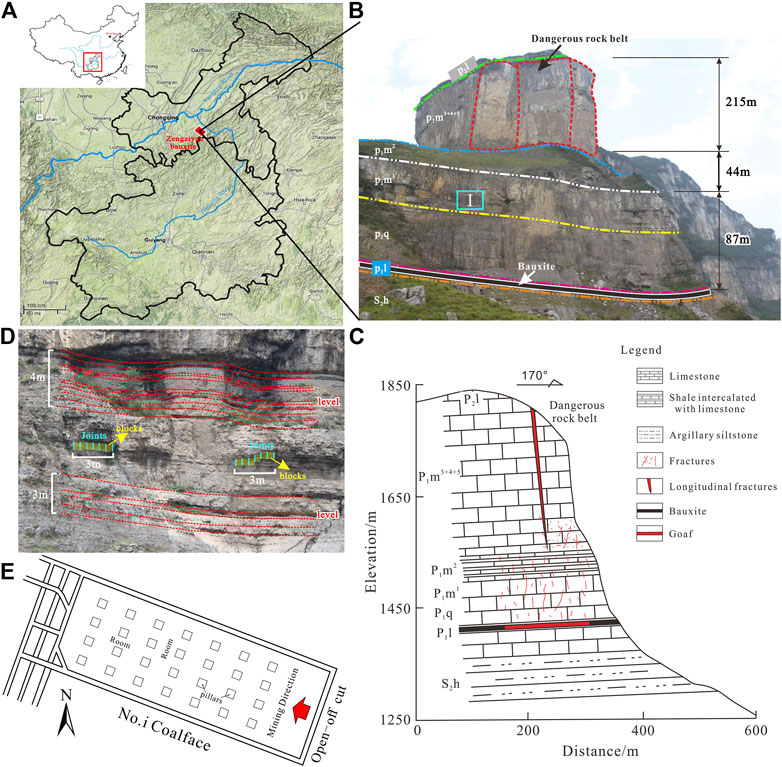
FIGURE 1. Zengziyan Bauxite Mine in Nanchuan District, Chongqing: (A) Location of Zengziyan Bauxite Mine (refer to Feng et al., 2014); (B) Mining geological conditions; (C) Section of overlying strata; (D) Stratigraphic structure (region I in Figure 1B); (E) Room-and-pillar mining face.
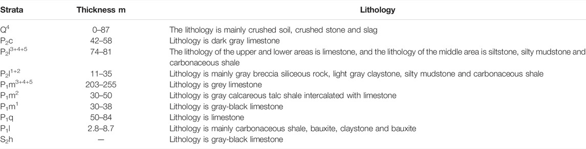
TABLE 1. Stratigraphy of the study area.
Room-and-pillar mining is the mining method. The maximum working face width (in the inclination direction) is 16 m. The specifications of the safety pillars are 5–8 m in the mining area (Figure 1E). The roof subsidence and floor bulging at the working faces in the Zengziyan Bauxite Mine are very common. Due to the long-term mining activities, 30 × 104 m3 of goaf have been formed. A series of dangerous rock collapse zones have formed above the goaf along the edge of the cliff, and several collapse failures have occurred. According to the field investigation report on the dangerous rock belt (Chongqing Geology and Mineral Exploration and Development Bureau, 2009) and previous studies (Feng et al., 2014; He, 2015), the soft foundation of shale intercalated with limestone of Maokou Formation (P1m2) of Permian System at the bottom of the rock collapse zones has undergone uneven subsidence and compression deformation. It is thought that the WCFZ is close to or has even reached the bottom of the soft foundation. However, according to the aditional mining experience, after thin-layer mining, the range of WCFZ is relatively small, and the WCFZ will not approach or reach the bottom of the damaged foundation, and thus, it will have no effect on the stability of the mountain foundation and will not cause mountain failure. Therefore, we carried out this study to analyze the mechanism of the migration and failure of the overlying strata and the development characteristics of the WCFZ in the mountainous carbonate areas in southwestern China.
3 Mechanical Method for Determining HWCFZ
3.1 Mechanism of Overlying Strata Failure
Prior to underground mining, the rock strata are subjected to the gravity of the overlying strata, and the surrounding rock is usually in an elastic deformation state under three-way compression. After the ore body is mined, the goaf becomes a pressure relief zone, and the stress of the original rock strata is redistributed. According to the new stress distribution in the surrounding rock, the overlying strata can be divided into a reduced stress area, an increased stress area, and an unchanged stress area (Qian et al., 2010). The block-shaped rock mass above the goaf is the reduced stress area, which is in an unloaded state. Since the vertical joints oriented perpendicular to the strata are relatively developed in the mountainous carbonate areas in southwestern China, the roof cannot be suspended above the goaf for an extended period of time. Under its own weight, it bends and migrates toward the goaf, causing horizontal separation fractures to form between the layers of the strata. In the vertical direction, the rock mass is subjected to tension, and the dominant longitudinal joints oriented perpendicular to the strata expand, forming connected and unconnected fractures. These two types of longitudinal fractures cause the rock mass to gradually break into blocks. During the crushing of the rock blocks, a typical three-hinged arch structure is formed (Yang, 2010; Gou and Chen, 2011). As the underground mining activities progress, the equilibrium state of the three-hinged arch structure of the roof is gradually broken from bottom to top, and instability of the roof periodically occurs, during which the unconnected fractures transform into connected fractures. During this process, the separation fractures crisscross with the connected fractures oriented perpendicular to the strata, forming the WCFZ. As the HWCFZ increases, the free space of the goaf continuously decreases due to the fragmentation heave characteristics of the rock blocks. When the height of the free space in the goaf is less than the ultimate subsidence of the three-hinged arch, that is, the unconnected fractures can no longer be transformed into connected fractures, the structure reaches an equilibrium state, and the WCFZ reaches its maximum height at this point (Figure 2). Because the three-hinged arch structure of the upper strata is not completely unstable, it only experiences bending and subsidence, with no connected fractures. This area is defined as the bending subsidence zone. Therefore, the stability of the three-hinged arch structure can be used as an indicator of whether the HWCFZ in the overlying strata reaches the maximum value. It should be noted that the roof is usually composed of rock formations with various thicknesses and strengths. During the fracturing process, failures occur throughout the entire thick stratum macroscopically, yet from the microscopic perspective, the failures occur layer by layer according to the layered structure of the rock mass, especially in sedimentary rocks such as limestone and sandstone. Based on the blocky structure of the rock mass in the study area, the three-hinged arch model and the theory of damage mechanics (Xie, 1990) were used to calculate the equivalent compressive strength

FIGURE 2. Sketch map of rock layer’s three-hinge arch failure after mining.
3.2 Ultimate Subsidence Si
3.2.1 Equivalent Compressive Strength
Due to the development of structural planes, especially vertical structural planes, in the study area, the rock mass was cut into blocks. Under mining disturbances, the overlying strata fractured into two blocks along the vertical structural plane first, and then, under their own weight, the two blocks subsided, with the middle joint acting as a hinge. In this situation, block 1 and block 2 formed a three-hinged arch (Figures 2, 3). According to previous researchers’ research on the rock mass structure, migration laws and equilibrium conditions of the overlying strata in the stope (Fayol, 1885; Evans, 1941; Qian, 1981; Qian and Miao, 1995a), after underground mining, due to the different curvatures of the displacement curves of the upper and lower strata, there are separation between layers. Therefore, itcan be considered that the upper and lower strata moved synchronously, without vertical contact, to maintain the three-hinged arch during the vertical subsidence. The stability of the three-hinged arch completely depends on the equivalent compressive strength and the equivalent bearing stress of the two blocks (Qian et al., 1994), and the crushing and failure of the contact surface lead to instability of the arch structure. Since the overlying strata is damaged media, the stress on the hinged blocks is usually concentrated, and the maximum compressive stress is often greater than the compressive strength of the rock mass, that is, the contact surface (CC´DD’) experiences compressive failure first. Therefore, in this study, we mainly considered the compressive force perpendicular to the contact surface.
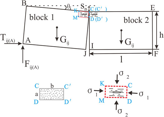
FIGURE 3. Three-hinged arch structure and damage area of contact surface (Note: Rectangle CC´DD’ is the contact surface of compression damage between rock blocks, and the rectangle CDKM is the magnified display of the tensile fractures caused by the compression during the crushing of the rock blocks, σ1, σ2, σ3 are the 1st, 2nd, and 3rd principal stress in the contact area, respectively, and their directions are the direction of mutual extrusion between the two rock blocks, Parallel to the direction of the longitudinal section between the blocks and parallel to the direction of the cross section of the stope.).
To calculate the equivalent compressive strength
FIGURE 4. Force diagram of rock block 1 in three-hinged arch structure.
The bending moment equation for point B:
Here, Tij(A) is the horizontal force of the left rock block on rock block 1, Tij(C) is the horizontal force of the right rock block on rock block 1, and Fij(A) is the vertical supporting force of the lateral rock wall. The layer thickness of the overlying strata is hi, and the joint spacing is lj. Gij is the weight of rock block 1,
The force balance equation in the vertical direction:
The force balance equation in the horizontal direction:
By combining Eqs 2–4, the horizontal force is obtained:
Based on the geometric relationships shown in Figure 4,
By combining Eqs 5–6, the horizontal force is obtained:
As mining progresses, the two rock blocks continue to migrate towards the goaf. During the crushing process, the rectangular contact surface (CC´DD´) (Figure 4) deforms first due to the stress concentration. The actual damage area is
where a is the occlusal thickness between the rock blocks (m), and
Therefore, the equivalent compressive strength between the two rock blocks is
3.2.2 Equivalent Bearing Stress
The brittle tensile fracturing is governed by the tensile strain ε3 (Sun and Sun, 2011). According to Hooke’s law,
where μ is the Poisson’s ratio of the overlying strata, ε3 is the tensile strain under three-dimensional compression, and E is the elastic modulus.
When the tensile strain ε3 is equal to the ultimate three-dimensional compressive tensile strain ε3,0, the rock mass undergoes tensile failure. It is assumed that during the migration of the three-hinged arch before the instability stage, the upper surface has never been in direct contact with the overlying stratum and the lower surface has never been in contact with the loose rock pile, that is, there is free space above and below the three-hinged arch. Thus, the intermediate principal stress is
If ε0 is the ultimate strain under uniaxial compression, then
where the third principal stress σ3 is equal to the horizontal stress σH of the deep fractured strata, i.e.,
By combining Eqs 10–12, the first principal stress perpendicular to the contact surface of the two blocks is obtained:
where w is the burial depth of the fractured roof, γ is the unit weight of the rock mass, and σc is the uniaxial compressive strength of the rock mass.
Considering the damage and deformation caused by the crushing effect of the two rock blocks, when the rock mass experiences compression-tension failure, the equivalent bearing stress
Substituting Equation (13) into Equation (14) gives
3.2.3 Ultimate Subsidence Si
Based on the equivalent compressive strength
When k = 1, the structure is in a stable state. By substituting Eqs 9, 15 into Eq. 16, the calculation formula for the ultimate subsidence Si of the three-hinged arch is obtained:
3.3 Height of the Free Space
After the ith roof stratum collapses and accumulates in the goaf. The distance between the top of the deposit and the incompletely caved roof is defined as the height of the free space
where M is the thickness of the ore layer, and h0 is the caving thickness of the directly overlying roof (the 0th roof). h1 is the caving thickness of the first roof stratum. hi is the caving thickness of the ith roof stratum.
The broken expansion coefficient of the 1st to ith roof strata can be replaced by the average broken expansion coefficient kave, which can be calculated using the following equation (Zhang et al., 1998):
where Wn is the subsidence at measuring point n, and h is the height at point n.
3.4 Calculation Flow-Process of HWCFZ
As mining progresses, the roof strata continue to undergo bending deformation, separation, and collapse, causing the height of the free space in the goaf to continuously decrease, and the HWCFZ of the overlying strata gradually increases. Using Eq. 17, the ultimate subsidence Si+1 of the three-hinged arch structure of the (i+1)th overlying stratum can be obtained. The HWCFZ is then calculated by comparing Si+1 and Hi. When Si+1 < Hi, the HWCFZ formed by the overlying strata reaches the maximum value. Thus, the criteria for determining the maximum height of the WCFZ is as follows (Figure 5).
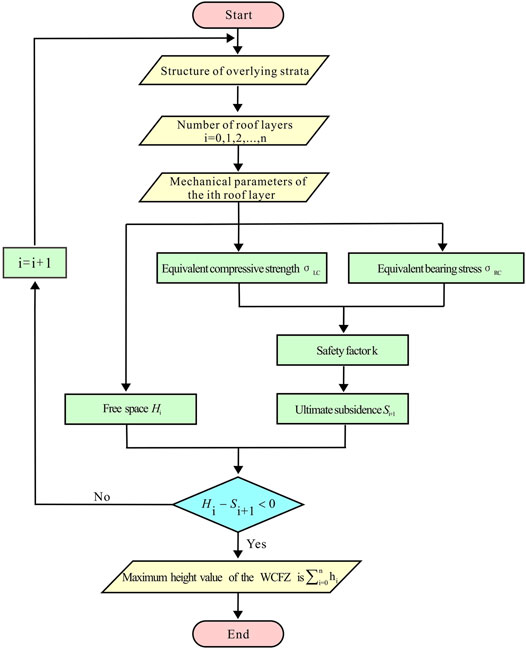
FIGURE 5. Calculation flow-process diagram of the maximum height of the WCFZ.
When
When
3.5 Calculation of HWCFZ
The overlying strata in the Zangziyan Bauxite Mine have a consistent lithology, i.e., layered limestone of medium thickness. Since the HWCFZ is relatively small compared to the burial depth of the overlying strata overall, the maximum value of 450 m was used to calculate the burial depth w of the fractured strata in the WCFZ in each cycle. According to Eq. 12, the confining pressure of the deep rock mass is σ3 = 2,385 kPa. Based on the vertical distance from each measurement point on line 4 to the ore and the Y-displacement measured at each point (refer to displacement field analysis in numerical simulation section), the average broken expansion coefficient kave of the roof strata was calculated to be 1.02 using Eq. 19. According to the field measurement data and a previous study (He, 2015), the mechanical parameters of the overlying strata were obtained (Table 2). Taking the second roof layer in the overlying strata as an example, the parameters were substituted into Eq. 17 to obtain the ultimate subsidence S2 of the three-hinged arch formed after the roof stratum collapsed, and a value of 0.3527 m was obtained. Then, using Eq. 18, the height of free space under the second roof stratum was calculated to be H1 = 2.18 m, so S2 = 0.3527 < H1 = 2.18 m. According to the criteria expressed in Eq. 20, the second roof stratum is currently in a fractured state, and thus, the HWCFZ will continue to increase. Similarly, the ultimate subsidence of the three-hinged arch formed by the collapse of the 3rd, 4th, … , (i+1)th layers was calculated, as well as the height of the free space Hi. Table 3 summarizes the fracture state of each roof stratum. Based on these calculations, the HWCFZ was obtained by adding the thicknesses hi of all of the collapsed roof strata, and a value of 92.5 m was obtained. The top surface of the WCFZ was located in the lower part of the P1m2 shale, which is intercalated with limestone.
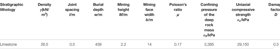
TABLE 2. Calculating parameters of HWCFZ in Zengziyan Bauxite.
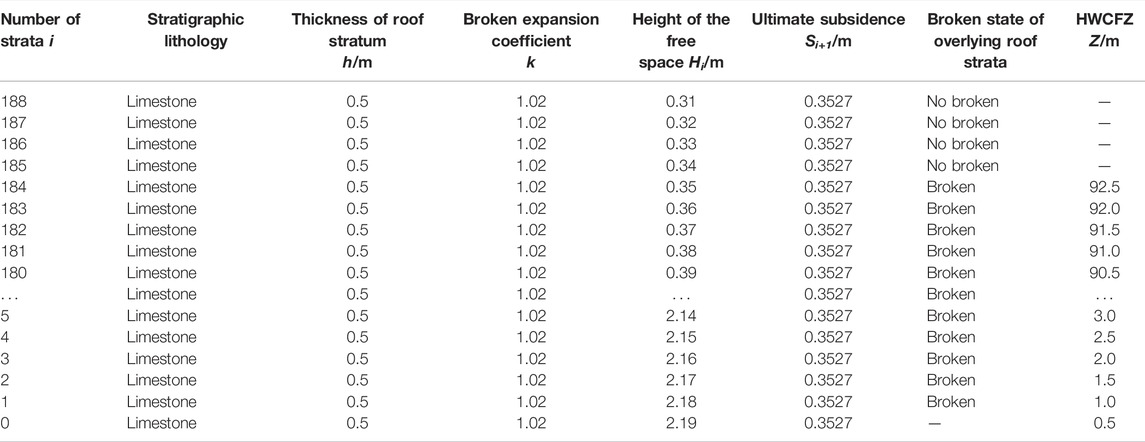
TABLE 3. Broken state of overburden roof strata of goaf.
4 Numerical Simulations
4.1 Establishing the Numerical Model
The UDEC software (Itasca, United States), which is based on the discrete element method, was used to create a two-dimensional numerical model of the Zengziyan Bauxite Mine according to the geology and mining scheme. This model was used to simulate the stress field, plastic zone, displacement field, and WCFZ development characteristics of the strata overlying the working face. The actual depth of the overlying strata was 450 m, the modeled depth was 131 m, and the thickness of the bedrock was about 17 m. The interface between the large thick P1m3+4+5 limestone and the P1m2 shale intercalated with limestone was set as the upper boundary of the model. The size of the model was 400 m × 150 m, and the thickness of the ore layer was 2.2 m. To eliminate the influences of the boundaries, 70 m safety pillars were set on each side of the model. The simulated mining procedure was as follows. The total mining distance was 258 m. The room and pillar method was used for the mining. The room width was 16 m, and the pillar width was 6 m. A total of 12 rooms were mined, and 11 pillars were created and then mined. The mining process was divided into three stages, including 14 steps (steps 1–4, 5–9, and 10–14). In each stage, four rooms were excavated simultaneously as a group, which were then connected after a certain distance to form square pillars. When mining the rooms, the pillars temporarily supported the roof. After the four rooms in each mining stage were mined, all of the pillars used in the previous stage were mined. Figure 6 shows mining steps 1 to 14. The boundary conditions were as follows: since the actual depth of the overlying strata was 450 m and the simulations only included 131 m, an initial vertical principal stress of 8.5 MPa was applied at the top of the model to simulate the weight of the 319 m of overlying strata. The Poisson’s ratio was used to calculate the horizontal stress component, which was applied to both sides to simulate the initial stress field. In the subsequent excavation simulations, the bottom was set as a fixed hinge support, i.e., fixed vertically with horizontal displacement, and the horizontal displacements of the sides of the model were fixed. The Mohr-Coulomb yield criterion was adopted. In order to measure the changes in the displacement field and stress field in each area of the model during the mining process, a total of four lines were set up at different positions in the rock strata. Specifically, three horizontal lines with lengths of 280 m were distributed from the top surface of the model to the top of the ore bed. Their distances to the top of the ore bed were 131, 87, and 30 m. Each line consisted of eight measurement points, with a spacing of 40 m. A longitudinal line (#4) was set up in the middle of the model. This line was 118 m long and consisted of six measurement points arranged from 11 m from the top of the ore layer to the top of the model, and the spacing between the six points was 30 m, except for point 4, which was located at the interface between P1m1 and P1m2 to monitor the displacement (Figure 6). The parameters used in the numerical simulations were the same as in a previous study (He, 2015) (Table 4).
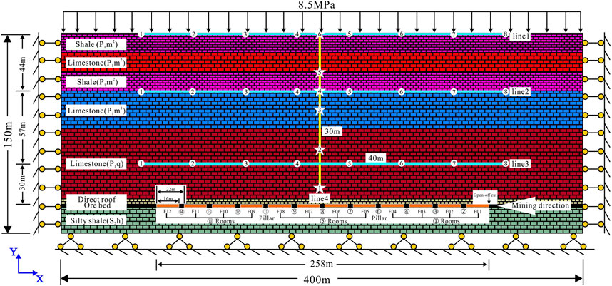
FIGURE 6. Engineering geological rock groups and boundary condilions of numerical model.
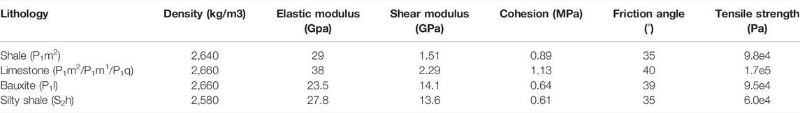
TABLE 4. Physical–mechanical parameters of the rock mass used in the numerical models.
4.2 Results and Analysis
4.2.1 Stress Field
In order to illustrate the stress changes in the overlying strata during the mining process, the first mining stage (i.e., steps 1–4) was analyzed. After the simultaneous mining of the four rooms began in the first stage, the stress of the overlying stratum behind the open-off cut and at the front of the working face did not change significantly compared with the original stress state; whereas the stress in the roof above the goaf was redistributed, and the stress path deflected from the original longitudinal direction into an arch pattern. The stress on the surrounding rock decreased from the 8 MPa compressive stress caused by gravity and the overlying pressure to 1 MPa. Moreover, the high stress area was transferred to the pillars on the sides of the goaf, causing the compressive stress to increase from 8 to 15 MPa (Zhu et al., 2022). The roof strata formed a typical pressure arch (Figure 7A). The pressure arch supported the rock strata from above the arch to the top of the model, and the upper rock strata did not experience bending and subsidence. With the recovery of the safety pillars, the pressure arch in the roof strata shifted forward as the working face continuously advanced from 70 to 76 m–80 m. In addition, the scale of the pressure arch expanded longitudinally and laterally, and the roof strata in the range of the pressure arch exhibited a decrease in the compressive stress or even the tensile stress. From the macroscopic perspective, the overlying strata experienced unloading relaxation and open fractures were generated (Figures 7B,C,D) (Zhang Y. et al., 2016).
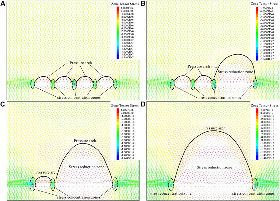
FIGURE 7. The dynamic change of the tensor stress zone of the overlying strata in the model, mining distance of coalface: (A) 64 m, (B) 70 m, (C) 76 m, (D) 82 m.
4.2.2 Characteristics of the Plastic Zone
In order to illustrate the changes in the plastic zone during the mining process, the first mining stage (i.e., steps 1–4) was analyzed. After the simultaneous mining of the four rooms began in the first stage, due to the pressure relief, the original compressive stress of the roof and floor strata of the goaf and the ore body was released, resulting in varying degrees of plastic deformation (Guo et al., 2018). Here, we only discuss the plastic deformation of the roof strata, which can be divided into three types: tensile deformation, shear deformation, and tensile-shear deformation. In this stage, due to the relatively small span of the goaf, the overall plastic deformation was small. The direct roof underwent tension deformation first, i.e., opening of the rock block along the dominant longitudinal joints, and the small area of old roof above the direct roof and the area above the mining boundary underwent shear deformation (Figure 8A).
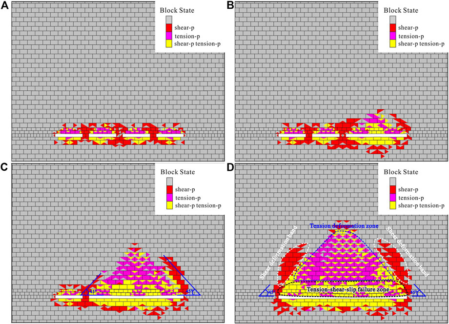
FIGURE 8. The dynamic change of the plastic zone of the overlying strata in the model, mining distance of coalface: (A) 64 m, (B) 70 m, (C) 76 m, (D) 82 m.
When the working face had continuously advanced to 70 m, the plastic deformation range became larger than that in the previous stage, and the type of plastic deformation of the roof changed. The middle of the roof at the maximum mining distance exhibited tensile-shear deformation, while the area on both sides of the roof and the area above exhibited tensile deformation. This was mainly due to the fact that the strata in the middle of the roof near the goaf were the first to form a three-hinged arch and to undergo tensile deformation. After the three-hinged arch became unstable, shear-slip failure occurred along the dominant longitudinal structural plane (Figure 8B). With the continuous advancement of the working face, the suspended area of the roof gradually increased, and the plastic zone in the roof strata increased significantly, exhibiting obvious zoning characteristics from bottom to top. Specifically, the lower roof mainly underwent tensile-shear deformation, forming a tension-slip failure zone. The upper roof was dominated by tensile deformation, forming a large tensile deformation zone. Shear deformation occurred in the area above the boundaries on both sides, forming a symmetrical shear deformation zone with a 45° angle towards the goaf. The tensile-slip failure zone was the most severely damaged and contained many connected fractures. This was the main area in which the WCFZ developed (Figures 8C,D).
4.2.3 Displacement Field
Figure 9 shows the Y-displacement at different measurement points on the three horizontal lines after mining. Based on the data, the closer the roof was to the goaf, the larger the longitudinal displacement was. Measurement points 3–6 experienced the maximum displacement (1.82 m), while the maximum displacements on line 2 and line 1 occurred at measurement point 5 near the middle of the goaf. Their longitudinal displacements were 0.68 and 0.33 m, respectively. Line 1 was located at the top of the model. It can be seen from Figure 9 that after the mining, a depression centered on the middle of the goaf appeared on the top of the model. The main reason for the differences in the longitudinal displacements in the different areas was that as the mining progressed, the separated rock strata gradually migrated downward to fill the goaf. Due to the fragmentation heave characteristics, the larger the distance from the roof strata to the goaf was, the smaller the height of the free space was, that is, the less space was available for the migration of the upper strata, and the smaller the displacement was. Line 4 in Figure 10 shows the dynamic change in the longitudinal displacement of the overlying strata in the middle of the goaf during the different mining stages. The overall migration speed exhibited a slow-fast-slow pattern. In steps 1–7, the measurement points on line 4 were not displaced. This is mainly because the ore seam in this area had not been mined. In step 8, point 1 was the first to undergo slight longitudinal displacement. In step 9, since the working face had advanced beyond the horizontal projection point of measurement point 1, the rock strata near this point were free to migrate toward the goaf, and the displacement of point 1 increased significantly (to 0.4 m). In addition, point 2 on line 4 started to experience longitudinal displacement. In step 11, measurement points 3, 4, 5, and 6 on line 4 all began to exhibit different degrees of displacement, and the migration rates of these points followed a certain pattern, i.e., 3 > 4 > 5 = 6. Point 4 was located at the interface between P1m1 and P1m2. When the mining was complete, the longitudinal displacement of point 4 was 0.47 m, which was larger than those of the other points on line 4, indicating that the WCFZ had reached the interface. This is consistent with the findings of the field investigation. In addition, points 5 and 6 moved synchronously after the migration began, indicating that there was no separation within the P1m2 shale intercalated with limestone. Thus, this area was a bending subsidence zone. Based on the above analysis, the top surface of the WCFZ was located between points 4 and 5 on line 4, i.e., the maximum range of the HWCFZ was 87–101 m. It should be noted that when the mining reached step 13, the longitudinal displacement of measurement point 1 on line 4 reached the maximum value of 1.98 m, and then, it remained unchanged during the subsequent mining. This indicates that under the action of the overlying strata and its own weight, all of the separation fractures in the strata below this point were completely closed, and there was no space available for further migration.
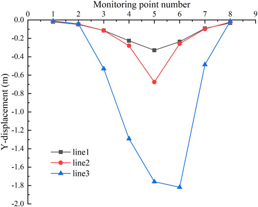
FIGURE 9. Y-displacement of horizontal lines.
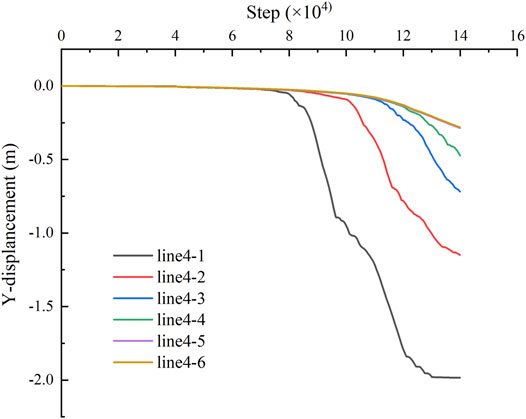
FIGURE 10. Y-displacement of line 4.
4.2.4 Dynamic Evolution of the WCFZ
The dynamic evolution of the HWCFZ is shown in Figure 11. After the commencement of the simultaneous mining of the four rooms in the first stage, because three 6 m safety pillars were temporarily retained, the roof overhang length was small, the roof strata were relatively stable, and thus, a WCFZ did not develop. When the working face had continuously advanced to 60 m, due to the long overhang length of the roof, bending and separation failure occurred in some areas in the overlying strata, which led to the formation of connected fractures. At this time, the HWCFZ was 17 m. When the last safety pillar from the first stage was mined, the maximum overhang length of the roof was 82 m; the WCFZ expanded upward; and its height reached 25 m. With the continuous advancement of the working face, the roof strata experienced periodic failure in the form of a three-hinged arch, which migrated toward the goaf. As a result, the HWCFZ gradually increased. When the working face had continuously advanced to 192 m, the HWCFZ was 85 m, which was near the interface between P1m1 and P1m2. When the working face had continuously advanced to 214 m, the HWCFZ developed in the lower shale strata of P1m2. At this time, the WCFZ reached the maximum height of 93 m. After this, the HWCFZ remained unchanged. However, the horizontal range of the WCFZ continued to increase with the advancement of the working face. The top of the fissure arch was an approximately horizontal line, and it was saddle-shaped (Liu et al., 2017). This is consistent with the HWCFZ range of 87–101 m obtained from the displacement analysis (Section 4.2.3). Moreover, it is also consistent with the HWCFZ of 92.5 m calculated using the theoretical equation (Section 3.5). Thus, the results demonstrate the effectiveness of the theoretical calculations and numerical simulations.
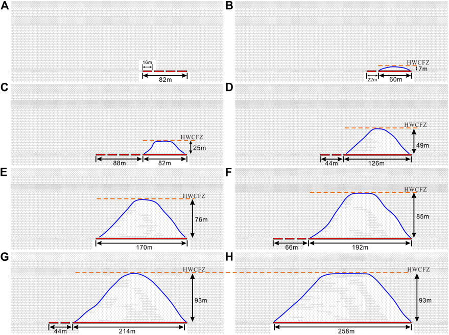
FIGURE 11. Height of the WCFZ as mining: (A) advancing 16 m continuously, (B) advancing 60 m continuously, (C) advancing 82 m continuously, (D) advancing 126 m continuously, (E) advancing 170 m continuously, (F) advancing 192 m continuously, (G) advancing 214 m continuously, (H) advancing 258 m continuously.
4.2.5 Common Law
With the continuous advancement of the working face, the stress field, plastic zone, displacement field and HWCFZ of overlying strata would change dynamically, but there was a positive feedback effect between them, that is, after the mine was mined, the stress field of the overlying strata was redistributed, and the roof strata formed a typical pressure arch. The overlying strata within pressure arch mainly underwent three types of plastic deformation, namely, tensile deformation, shear deformation, and tensile-shear deformation, and the plastic deformation exhibited obvious zonal characteristics. The closer the overlying strata was to the goaf, the greater the degree of deformation, which was mainly manifested as tensile-shear deformation, and the displacement field was also larger. In this situation, the roof strata experienced periodic failure in the form of a three-hinged arch, which migrated toward the goaf. As a result, the HWCFZ gradually increased. As the goaf was gradually filled by the overlying strata, the variation of the stress field of overlying strata from the bottom to top gradually weakened, the plastic deformation and the change of the displacement field became slower, and the HWCFZ grew slowly. When the separation fractures in the strata were basically closed, the HWCFZ no longer increased and it reached the maximum value. At this time, its outline was saddle-shaped.
5 Discussion
5.1 Inapplicability of Traditional Empirical Formulas
Currently, the empirical formulas for calculating the HWCFZ given in the Regulation for Coal Pillar Retention and Coal Mining in Buildings, Water Bodies, Railways, and Mine Shafts is widely used (State Administration of Work Safety, 2017). In this paper, the HWCFZ was calculated by substituting the physical and mechanical parameters of the overlying strata in the Zengziyan Bauxite Mine into empirical formulas 1 and 2, and the results were compared with those obtained based on the theoretical formula and numerical simulations considering the structural rock mass. The results are shown in Table 5. The values calculated from the theoretical formula and the numerical simulations were much higher (2.5–3.7 times and 8.4 times, respectively) than the values calculated from the empirical formula. This suggests that the results from the traditional empirical formulas have large errors and are not applicable to calculating the HWCFZ in the mining areas of mountainous carbonate areas in southwestern China. This is mainly because the empirical formulas were derived based on measurement data for mines in northern China, and these mines mainly have loose strata structures or thick loose strata-bedrock structures. The traditional empirical formulas only consider the thickness of the ore seam and the rough strength of the strata, and they do not consider the structure, the physical or mechanical parameters of the rock mass (e.g., the rock mass’s strength and broken expansion behavior), or the burial depth of the ore body. Therefore, the prediction of the HWCFZ in different mines should be performed based on the actual local geological conditions and mining conditions, rather than by directly adopting existing methods. Only in this way can accurate predictions be achieved and science-based support provided for safe production. Of course, for many mines in the mountainous carbonate areas in southwestern China, there are multiple sets of mineable layers under the ground. Compared with single-layer mining, multiseam mining tends to cause more serious failure to the overlying strata, and the development height of WCFZ is higher. This study only considers the influence of single-layer mining on the migration and failure of overlying strata and development of the HWCFZ. The theoretical method proposed in this study should be updated and expanded in the later stage, and it should be applied to research the migration and failure of overlying strata and development of the HWCFZ during the multiseam mining process.
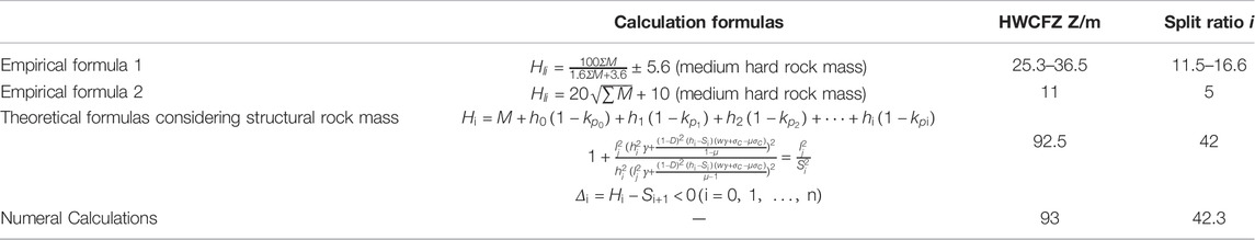
TABLE 5. Comparison of calculation results between the empirical formulas, theoretical formulas, and numerical simulations.
5.2 Instability Mechanism of Mining-Type Mountains
The mountainous carbonate areas in southwestern China (e.g., Sichuan-Chongqing, Yunnan-Guizhou, western Hunan, and western Hubei) are folded mountainous areas. The rock masses were mainly deposited in a marine-terrestrial interaction-terrestrial depositional environment, and the stratigraphic lithologies are mainly composed of Permian and Triassic carbonate rocks such as limestone and dolomite, and clastic rocks such as sandstone. The average layer thickness of the rock mass is less than 1 m. The proportion of the overlying strata that is composed of hard rock is >90%. The burial depth of the ore bed in this area is generally 40–300 m (Xie and Wang, 2012), and the thickness of the ore bed is generally less than 2.5 m. That is, this area is characterized by a shallow burial depth and a thin mining thickness. The geological structure is complex, and there are multiple sets of dominant longitudinal structural planes, which are densely developed. The thin-layered and medium-thickly layered rock mass is cut into massive structures (Figure 12), and the spacing between the structural planes is 0.2–1.0 m. Thin ore layers are mined under loose cohesive soil layers, soft rock layers, and thick and extremely thick structural hard rock masses. Previous studies have concluded that after thin-layer mining in this area, the WCFZ will not reach the bottom of the thick and extremely thick structural hard rock mountain, so the base will not be damaged, and thus, the WCFZ will have no effect on the stability of the base of the mountain. However, a large number of case studies have shown that with the continuous intensification of the mining of the thin ore beds in the southwestern carbonate mountainous areas, many overall collapse disasters have occurred in the overlying mountains (Yin et al., 2010; Zhao et al., 2016a; Li et al., 2016b; Cui et al., 2021). Through field investigations in recent years, it has been found that the overlying strata are bent, deformed, and fractured due to underground mining, gradually forming fracture zones, and the HWCFZ formed as a result of the underground mining under the hard rock caprock has increased significantly (Chen and Zhu, 2020). The increase in the WCFZ in the overlying strata causes uneven subsidence of the upper strata near the base of the dangerous rock mass, forming an uneven subsidence zone, which in turn causes damage and fracturing of the base of the dangerous rock mass and pulling of the top of the rock mass. The combined effect described above has resulted in the overall instability of the mountain (Figure 13) (Li et al., 2015; Li et al., 2016b; Zhao et al., 2016b; Li et al., 2020a). The closer the top boundary of the WCFZ is to the bottom boundary of the folded mountain collapse zone, the more prone the mountain is to instability. Therefore, the HWCFZ of the structural rock mass is the key factor controlling the stability of the mining-type mountains. The focus of future research should be on the influence of the increase in the HWCFZ in the overlying strata on the stability of the upper part of the mountain, and subsequently, the instability process and mechanism of the mining-type Mountains should be studied. Considering that the deformation of hard rock mountain induced by thin-bed mining is a long-term process, the fissure flow formed by groundwater often leads to accelerating deformation of the structural overlying strata. Furthermore, the long-term monitoring of some parameters such as the stress field, displacement field and groundwater field of the overlying strata should be carried out, which is conducive to the later study about the instability process and mechanism of mining-type mountain.
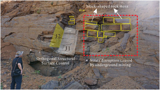
FIGURE 12. Typical blocky structure of overlying strata in the southwest carbonate mountainous area.
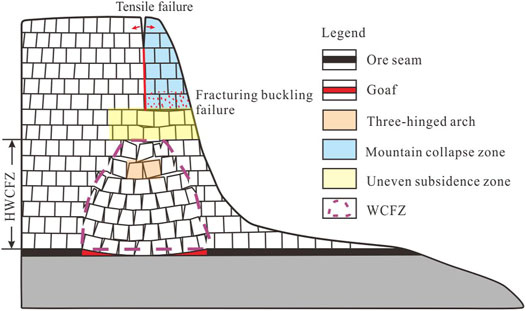
FIGURE 13. Typical slope instability model in the southwest carbonate mountainous area.
6 Conclusion
In this study, through theoretical analysis and numerical simulations, we investigated the geological structure characteristics of underground mining, the migration and failure mechanism of the overlying strata and the development of the HWCFZ during the mining process in the Zengziyan Bauxite Mine. The main conclusions are as follows.
1) In the process of underground mining in the mountainous carbonate areas in southwestern China, it is necessary to consider the block-shaped rock mass structure characteristics of carbonate rocks, and the instability model of three-hinged arch structure can be used to determine the HWCFZ. This analysis method makes the prediction result of overlying strata slump height more accurate, which is beneficial to the evaluation of mountain stability.
2) Numerical analysis revealed the variation characteristics of stress field, plastic zone and displacement field of structural overlying strata during the mining process. After mining and pressure relief, there were mainly three types of plastic deformation in the range of pressure arch, including tensile deformation, shear deformation and tensile-shear deformation, and the plastic deformation exhibited obvious zonal characteristics. The HWCFZ obtained through the numerical calculations was consistent with the results of the theoretical calculations (93 vs. 92.5 m), which validated the reliability and accuracy of the theoretical calculation method.
3) In the mountainous carbonate areas in southwestern China, underground mining leads to the significant increase of the HWCFZ in the overlying structural strata, resulting in landslide disasters in the overlying mountains. Therefore, it is necessary to pay attention to the monitoring of the main areas, including the WCFZ in the overlying strata in the goaf, the uneven subsidence zone, and the mountain collapse zone.
Data Availability Statement
The original contributions presented in the study are included in the article/Supplementary Material, further inquiries can be directed to the corresponding author.
Author Contributions
JL and BL analyzed, wrote, and processed the data; YG provided opinions on the writing of the paper; FC participated in the numerical calculations; KH participated in the field survey; JL and HL modified the format. All of the authors have read and agreed to the published version of the manuscript.
Funding
The authors would like to sincerely thank the funding agencies that supported this research. This work was supported by the National Key R&D Program of China (No. 2018YFC1504806) and the National Science Foundation of China (No. 41907257).
Conflict of Interest
The authors declare that the research was conducted in the absence of any commercial or financial relationships that could be construed as a potential conflict of interest.
Publisher’s Note
All claims expressed in this article are solely those of the authors and do not necessarily represent those of their affiliated organizations, or those of the publisher, the editors and the reviewers. Any product that may be evaluated in this article, or claim that may be made by its manufacturer, is not guaranteed or endorsed by the publisher.
References
Aitao, Z., and Kai, W. (2018). A New Gas Extraction Technique for High-Gas Multi-Seam Mining: A Case Study in Yangquan Coalfield, China. Environ. Earth Sci. 77 (4), 1–16. doi:10.1007/s12665-018-7291-z
Altun, A. O., Yilmaz, I., and Yildirim, M. (2010). A Short Review on the Surficial Impacts of Underground Mining. Sci. Res. Essays. 5 (21), 3206–3212. doi:10.5897/SRE.9000106
Chen, Y., and Zhu, S. (2020). Determination of Caved and Water-Conducting Fractured Zones of "two Soft and One Hard" Unstable Coal Seam. Acta Geod Geophys. 55 (3), 451–475. doi:10.1007/s40328-020-00300-w
Chongqing Geology and Mineral Exploration and Development Bureau (2009). Investigation and Evaluation Report on the Dangerous Rock Belt from Zengziyan to Guanyin Cave in Jinfo Mountain. Chongqing: Nanchuan District.
Cui, F., Li, B., Xiong, C., Yang, Z., Peng, J., Li, J., et al. (2021). Dynamic Triggering Mechanism of the Pusa Mining-Induced Landslide in Nayong County, Guizhou Province, China. Geomatics, Nat. Hazards Risk 13 (1), 123–147. doi:10.1080/19475705.2021.2017020
Diederichs, M. S., and Kaiser, P. K. (1999). Tensile Strength and Abutment Relaxation as Failure Control Mechanisms in Underground Excavations. Int. J. Rock Mech. Mining Sci. 36 (1), 69–96. doi:10.1016/S0148-9062(98)00179-X
Fan, H., Wang, L., Lu, Y., Li, Z., Li, W., and Wang, K. (2020). Height of Water-Conducting Fractured Zone in a Coal Seam Overlain by Thin Bedrock and Thick Clay Layer: A Case Study from the Sanyuan Coal Mine in North China. Environ. Earth Sci. 79 (6), 1–11. doi:10.1007/s12665-020-8873-0
Fathi Salmi, E., Nazem, M., and Karakus, M. (2017). Numerical Analysis of a Large Landslide Induced by Coal Mining Subsidence. Eng. Geology. 217, 141–152. doi:10.1016/j.enggeo.2016.12.021
Fayol, M. (1885). Sur Les Movements De Terain Provoques Par L’exploitation Des Mines. Bull. Soc. L'ind Minerale. 14, 818.
Feng, Z., Li, B., Yin, Y. P., and He, K. (2014). Rockslides on Limestone Cliffs with Subhorizontal Bedding in the Southwestern Calcareous Area of China. Nat. Hazards Earth Syst. Sci.Earth Sys 14 (9), 2627–2635. doi:10.5194/nhess-14-2627-2014
Gou, X., and Chen, R. (2011). Three-Hinged Arch Structure Stability of Mining Overlying Strata. J. Liaoning Tech. Univ. (Nat Sci). 30 (S1), 70–73.
Guo, W., Zhao, G., Lou, G., and Wang, S. (2018). A New Method of Predicting the Height of the Fractured Water-Conducting Zone Due to High-Intensity Longwall Coal Mining in China. Rock Mech. Rock Eng. 52 (8), 2789–2802. doi:10.1007/s00603-018-1567-1
He, K. (2015). Research on Collapse Mechanism of Tower Rock. PhD Thesis. Xi’an, China: Chang’an University.
Hou, E., Wen, Q., Ye, Z., Chen, W., and Wei, J. (2020). Height Prediction of Water-Flowing Fracture Zone with a Genetic-Algorithm Support-Vector-Machine Method. Int. J. Coal Sci. Technol. 7 (4), 740–751. doi:10.1007/s40789-020-00363-8
Hu, X., Li, W., Cao, D., and Liu, M. (2012). Index of Multiple Factors and Expected Height of Fully Mechanized Water Flowing Fractured Zone. J. China Coal Soc. 37 (4), 613–620. doi:10.13225/j.cnki.jccs.2012.04.026
Jin, K., Cheng, Y., Wang, L., Dong, J., Guo, P., An, F., et al. (2015). The Effect of Sedimentary Redbeds on Coalbed Methane Occurrence in the Xutuan and Zhaoji Coal Mines, Huaibei Coalfield, China. Int. J. Coal Geology. 137, 111–123. doi:10.1016/j.coal.2014.11.009
Kang, J., He, W., and Hu, H. (2000). Analysis of Surface Deformation and Slope Stability Caused by Mining in Mountainous Areas. Beijing: China Science and Technology Press.
Li, B., Feng, Z., Zhang, Q., Zhao, C., Yan, J., Gao, Y., et al. (2016a). Researches on Formation Modes and Early Identification of Mega-Landslides in the Mountainous Karst Areas. Beijing: Science Press.
Li, B., Feng, Z., Wang, G., and Wang, W. (2016b). Processes and Behaviors of Block Topple Avalanches Resulting from Carbonate Slope Failures Due to Underground Mining. Environ. Earth Sci. 75 (8), 1–26. doi:10.1007/s12665-016-5529-1
Li, B., Wang, G., Feng, Z., and Wang, W. (2015). Failure Mechanism of Steeply Inclined Rock Slope Induced by Underground Mining. Chin. J. Rock Mech. Eng. 34 (6), 1148–1161. doi:10.13722/j.cnki.jrme.2014.0974
Li, J., Chu, H., Li, B., He, K., and Gao, Y. (2020a). The Key Scientific Issues of the Landslide Disasters Research Induced by Underground Mining in the Coal-Related Sedimentary Rock Strata Mountain Area of Southwestern China. Carso Sin 39 (4), 453–466. doi:10.11932/karst20200401
Li, L., Li, F., Zhang, Y., Yang, D., and Liu, X. (2020b). Formation Mechanism and Height Calculation of the Caved Zone and Water-Conducting Fracture Zone in Solid Backfill Mining. Int. J. Coal Sci. Technol. 7 (1), 208–215. doi:10.1007/s40789-020-00300-9
Liu, S., Li, W., and Wang, Q. (2017). Height of the Water-Flowing Fractured Zone of the Jurassic Coal Seam in Northwestern China. Mine Water Environ. 37 (2), 312–321. doi:10.1007/s10230-017-0501-1
Liu, T. (1981). Mining Influence Caused by Large-Scale Stope and its Temporal and Spatial Distribution. Mine Surv. (1), 70–77.
Liu, X., Tan, Y., Ning, J., Tian, C., and Wang, J. (2015). The Height of Water-Conducting Fractured Zones in Longwall Mining of Shallow Coal Seams. Geotech. Geol. Eng. 33 (3), 693–700. doi:10.1007/s10706-015-9851-2
Mondal, D., Roy, P. N. S., and Kumar, M. (2020). Monitoring the Strata Behavior in the Destressed Zone of a Shallow Indian Longwall Panel with Hard Sandstone Cover Using Mine-Microseismicity and Borehole Televiewer Data. Eng. Geology. 271, 105593. doi:10.1016/j.enggeo.2020.105593
Ning, J., Wang, J., Tan, Y., and Xu, Q. (2020). Mechanical Mechanism of Overlying Strata Breaking and Development of Fractured Zone during Close-Distance Coal Seam Group Mining. Int. J. Mining Sci. Technology 30 (2), 207–215. doi:10.1016/j.ijmst.2019.03.001
Nomikos, P. P., Sofianos, A. I., and Tsoutrelis, C. E. (2002). Structural Response of Vertically Multi-Jointed Roof Rock Beams. Int. J. Rock Mech. Mining Sci. 39 (1), 79–94. doi:10.1016/S1365-1609(02)00019-9
Qian, M. (1981). Equilibrium Conditions of Overlying Strata in the Stope. J. Chin. Aca. Min. Tech. (2), 34–43.
Qian, M., Miao, X., and He, Fu. (1994). Key Block Analysis of "Masonry Beam" Structure in the Stope. J. China Coal Soc. 19 (6), 557–563.
Qian, M., and Miao, X. (1995a). Morphology and Stress Analysis of the Overlying Strata in the Stope. Chin. J. Rock Mech. Eng. 14 (2), 97–106.
Qian, M., and Miao, X. (1995b). Theoretical Analysis on the Structural Form and Stability of Overlying Strata in Longwall Mining. Chin. J. Rock Mech. Eng. 14 (2), 97–106.
Qian, M., Shi, P., and Xu, J. (2010). Mine Pressure and Rock Formation Control. Xuzhou: China University of Mining Tech Press.
State Administration of Work Safety (2017). Regulation for Coal Pillar Retention and Coal Mining in Buildings, Water Bodies, Railways and Main Shafts. Beijing: Coal Industry Press.
Wang, J., Zhao, Z., and Hou, Z. (2007). Study on the Catastrophic Collapse of Surface Land Induced by Mining under A Shallow and Hard Strata. J. China Coal Soc. 32 (10), 1051–1056.
Xie, H. (1990). Damage Mechanics of Rock and Concrete. Jiangsu: China University of Mining and Technology Press.
Xie, H., and Wang, M. (2012). Geological Hazards of Coal-Mining Subsidence and Types of Subsidence Area in Guizhou. J. Guizhou Univ. (Nat. Sci). 29 (3), 128–131. doi:10.15958/j.cnki.gdxbzrb.2012.03.035
Xu, J., Wang, X., Liu, W., and Wang, Z. (2009). Effects of Primary Key Stratum Location on Height of Water Flowing Fracture Zone. Chin. J. Rock Mech. Eng. 28 (2), 380–385.
Xu, J., Zhu, W., and Wang, X. (2012). New Method to Predict the Height of Fractured Water-Conducting Zone by Location of Key Strata. J. China Coal Soc. 37 (5), 762–769. doi:10.13225/j.cnki.jccs.2012.05.002
Yang, Z. L. (2010). Stability of Nearly Horizontal Roof Strata in Shallow Seam Longwall Mining. Int. J. Rock Mech. Mining Sci. 47 (4), 672–677. doi:10.1016/j.ijrmms.2010.03.001
Yi, T., Han, X., Weitao, Y., Wenbing, G., Erhu, B., Tingye, Q., et al. (2022). Study on the Overburden Failure Law of High-Intensity Mining in Gully Areas with Exposed Bedrock. Front. Earth Sci. 10, 295. doi:10.3389/feart.2022.833384
Yin, Y., Sun, P., Zhang, M., and Li, B. (2010). Mechanism on Apparent Dip Sliding of Oblique Inclined Bedding Rockslide at Jiweishan, Chongqing, China. Landslides 8 (1), 49–65. doi:10.1007/s10346-010-0237-5
Zhang, D., Deng, K., and Zhou, M. (1998). Study on the Change Law of the Broken Expansion Coefficient of Mining Rock Mass. Jiangsu Coal (1), 3–5.
Zhang, J., Zhang, K., Cao, Z., and Zhang, Y. (2016). Mining-Bursting Simulation and Height Calculation Method for Conducting-Water Fractured Zone. J. China Coal Soc. 42 (6), 1557–1564. doi:10.13225/j.cnki.jccs.2016.1720
Zhang, Y., Ye, J., Ji, H., and Wang, J. (2016). Identifying the Development of Mining-Induced Fractures Zone Using Dynamic Stress Tracing Method. Rock Soil Mech. 37 (11), 3291–3298+3323. doi:10.16285/j.rsm.2016.11.031
Zhao, J., Lin, B., Ma, Y., Zhang, X., Lan, Z., and Huang, R. (2016a). Physical Modeling on Deformation Characteristics of Overlying Rock Mass above Mined-Out Area in Gently Inclined Coal Seam. J. China Coal Soc. 41 (6), 1369–1374. doi:10.13225/j.cnki.jccs.2015.1408
Zhao, J., Xiao, J., Lee, M. L., and Ma, Y. (2016b). Discrete Element Modeling of A Mining-Induced Rock Slide. Springerplus 5 (1), 1–19. doi:10.1186/s40064-016-3305-z
Zheng, D., Frost, J. D., Huang, R. Q., and Liu, F. Z. (2015). Failure Process and Modes of rockfall Induced by Underground Mining: A Case Study of Kaiyang Phosphorite Mine Rockfalls. Eng. Geology. 197, 145–157. doi:10.1016/j.enggeo.2015.08.011
Zhu, T., Li, W., Wang, Q., Hu, Y., Fan, K., and Du, J. (2020). Study on the Height of the Mining-Induced Water-Conducting Fracture Zone under the Q2l Loess Cover of the Jurassic Coal Seam in Northern Shaanxi, China. Mine Water Environ. 39 (1), 57–67. doi:10.1007/s10230-020-00656-z
Keywords: mountainous carbonate areas in southwestern China, thin-bed mining, structure of overlying strata, HWCFZ, calculation method
Citation: Li J, Li B, Gao Y, Cui F, He K, Li J and Li H (2022) Mechanism of Overlying Strata Migration and Failure During Underground Mining in the Mountainous Carbonate Areas in Southwestern China. Front. Earth Sci. 10:874623. doi: 10.3389/feart.2022.874623
Received: 12 February 2022; Accepted: 14 March 2022;
Published: 12 April 2022.
Edited by:
Faming Huang, Nanchang University, ChinaReviewed by:
Jinyu Dong, North China University of Water Conservancy and Electric Power, ChinaQihang Li, Jiangxi University of Science and Technology, China
Junwen Zhang, China University of Mining and Technology, Beijing, China
Copyright © 2022 Li, Li, Gao, Cui, He, Li and Li. This is an open-access article distributed under the terms of the Creative Commons Attribution License (CC BY). The use, distribution or reproduction in other forums is permitted, provided the original author(s) and the copyright owner(s) are credited and that the original publication in this journal is cited, in accordance with accepted academic practice. No use, distribution or reproduction is permitted which does not comply with these terms.
*Correspondence: Bin Li, NTI1NzI3MDZAcXEuY29t