 Cong Liu
 Bo Wu
Bo Wu Rui Li3
94% of researchers rate our articles as excellent or good
Learn more about the work of our research integrity team to safeguard the quality of each article we publish.
Find out more
ORIGINAL RESEARCH article
Front. Earth Sci., 25 April 2022
Sec. Geohazards and Georisks
Volume 10 - 2022 | https://doi.org/10.3389/feart.2022.870710
This article is part of the Research TopicApplications of Geotechnical Mechanics in Underground EngineeringView all 41 articles
The presence of a base cavity will degrade the bearing capacity of tunnel bottom structures, and will also have a noteworthy impact on its fatigue performance. In order to study the fatigue performance and cumulative damage to tunnel bottom structure, a series of bending fatigue tests are conducted by reference to a heavy haul railway tunnel with a base cavity. Through the tests, fatigue evolution characteristics of tunnel bottom structure with cavity are obtained, then based on the expression of S-N curves, a non-linear fatigue cumulative damage model is therefore proposed, the deflection evolution and cumulative damage evolution can be divided into three stages, and characterized with an “s-shaped” curve. The tests results reveal that the damage to the tunnel bottom structure develops rapidly when a cavity exists in the base rock, fatigue occurs more easily, and the fatigue life of specimens decreases with the increase of the stress level and cavity width.
Railway capacity and efficiency have improved considerably along with the increase in train axle load (Tian, 2015), so railway departments all over the world are competing to improve the axle load of freight railways (Lei et al., 2019; Huang et al., 2020). However, with the increasing operation period and axle load resulting from intensive development of heavy haul transportation, basal degradation is emerging in more and more heavy-haul railway tunnels (Tian, 2014), and it is very difficult to deal with owing to the distinguishing features of heavy haul railway tunnels in China: high traffic density, short maintenance interval, and limited working space. This seriously restricts the economic benefits of heavy haul railway. For example, the Daqin heavy haul railway in China is the world’s leading railway by freight volume; after more than two decades of operation, many severe cases of tunnel basal degradation were found, such as cavities and mud pumping, which resulted in serious train shaking (Hu, 2015). Nowadays, the probability of basal diseases in Daqin railway is increasing with the increase in operation period (Liu et al., 2020). Severe tunnel bottom diseases also emerged in Shuohuang heavy haul railway (Yin et al., 2013), and Wari heavy haul railway (Li et al., 2021), most of the basal deterioration is appearing on the side of the full-load track.
For a long time, through a series of experimental studies, researchers reported fatigue would not occur in the tunnel bottom structure (Van Rickstal et al., 1999). Therefore, in the past, the design of tunnel bottom structures has been relatively thin and vulnerable. Nowadays, researchers have found that support conditions affect the fatigue performance of tunnel bottom structures remarkably (Liu et al., 2020).
Fatigue failure would be unlikely to occur when the tunnel bottom structure lies on a continuous and stable foundation. For example, Han et al. (2017) and Qian et al. (2019) indicated that segments of the shield tunnel bottom would be stable for the designed service life (100 years) using fatigue tests, Liu et al. (2019) suggested that fatigue failure will not occur in the bottom structures of a newly designed heavy haul railway tunnel within 100 years if bedrock defects are lacking and the pressure of the surrounding rock is not excessive.
When the basement supporting conditions deteriorated, such as cavities existing in the base rock, the stress of the tunnel bottom structure will increase obviously, and its fatigue performance will be reduced sharply (Zhang et al., 2020), then leading to deterioration and failure of the liner (Wang et al., 2014). Through numerical simulation, Zhang et al. (2018) indicated that the settlement and principal stress of tunnel bottom structures would increase when a base cavity exists and suggested that fatigue failure would occur in tunnel bottom structures if the base cavity width is greater than 2 m. Liu et al. (2016) implies that fatigue failure will occur in tunnel bottom structures within 100 years if the base cavity width is larger than 1 m. Based on bending fatigue tests, Liu et al. (2020) indicated that base cavities have multiple adverse effects on fatigue performance of tunnel bottom structures, and the probability of fatigue failure in heavy haul railway tunnels will be greatly increased. By model testing, Dong et al. (2020) studied the dynamic response of crossing tunnels under heavy haul train load, the results revealed that the vibration of intersections are more significant than in the common sections, because of the presence of the lower tunnel (like a void). Through field investigation and experiments, Li et al. (2021) indicated that the tunnel base cavity is mainly caused by the long-term coupling effect of train load and groundwater erosion.
The smoothness of tunnel base directly affects the safety of train operation (Cai et al., 2019; Lazorenko et al., 2019), and tunnel base diseases are usually difficult to detect and deal with due to the distinguishing features of heavy haul railway in China; hence, base diseases become one of the most harmful tunnel diseases (Kim et al., 2020). Therefore, with the increasing axle load and the basal deterioration of the existing heavy haul railway in China, studying the fatigue performance and cumulative damage of the tunnel bottom structure with a cavity is essential.
Through field investigation, it is found that after decades of operation, due to the water erosion and the accumulated settlement of the soft foundation, the width of the basement cavity is increasing, which will deteriorate the support conditions of the tunnel bottom structure, and then leads to serious basement diseases such as train shaking, mud boiling and so on. Tunnel base diseases of Daqin heavy haul railway mainly occur in two positions: the lower part of the track (Figure 1A), and the connection between the side drain and sidewall, shown in Figure 1B.
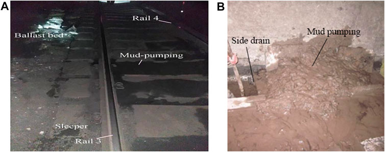
FIGURE 1. Mud pumping in a tunnel of Daqin heavy haul railway. (A) mud-pumping below the rail; (B) mud-pumping from the side drain.
The tunnel is located at Daqin heavy haul railway in China, which has the world’s highest annual freight volume (average 440 million tons each year in 2013–2019, total volume is 572 million tons each year which including the train volume); its common axle load is 27 t, maximum axle load is 30 t; the speed of the full-load train is about 70 km/h, the empty train speed is 90 km/h.
The section design chart of the Daqin heavy haul railway tunnel with a base cavity is illustrated in Figure 2. The defects emerged in grade-III surrounding rock (351≤ BQ ≤450). The tunnel size: 10.3 m × 9.0 m (width × height), shown in Figure 2A. The vault, sidewall, and bottom structure are all adopted plain concrete. The bottom structure is 10 cm thick (Figure 2B).
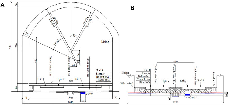
FIGURE 2. Section diagram of the tunnel with base disease. (A) tunnel section; (B) bottom structure.
The bottom structure below rail 3 is a potentially vulnerable position because its dynamic response is the largest (Liu et al., 2020). So the cavity is placed below rail 3, cavity size: 300 mm × 100 mm (width × height).
The vulnerable position is selected for the fatigue test, based on its stress and support characteristics, three-point bending fatigue test is used to investigate the fatigue behavior of the tunnel bottom structure with a cavity. The specimen is placed on the supporting basement, and the distance between the two supports is 300 mm, which represents the cavity that exists in tunnel base rock, shown in Figure 3.
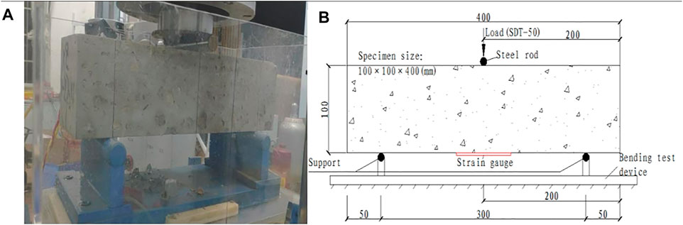
FIGURE 3. Test with 300 mm base cavity. (A) test devices; (B) Loading position and support.
To simulate the base rock support in the test without a base cavity, springs are placed under the specimen to simulate the support of the tunnel bottom structure. In total 10 × 3 springs are arranged in the area of 300 mm × 80 mm at the bottom of the specimen, shown in Figure 4. The static stiffness of the spring is 400 kN/m according to the mechanical properties of the surrounding rock (GB/T 50081 2002, 2003).
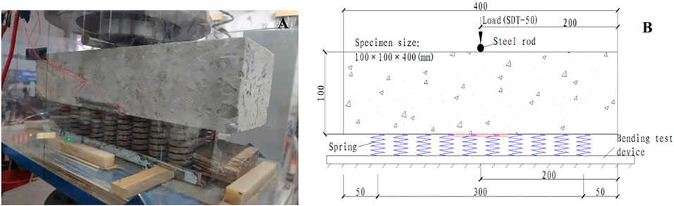
FIGURE 4. Test without base cavity. (A) test devices; (B) Loading position and support.
Standard bending specimens and supporting board (GB/T 50081 2002, 2003) are adopted in the tests. The specimen size: 100 mm × 100 mm × 400 mm (length × width × thick). The supporting board size: 400 mm × 150 mm × 12 mm (length × width × thick), the span between the 2 supports: 300 mm. The diameter of the steel rod is 22 mm, and the length is 120 mm (Figure 4A).
Cyclic train load is applied by dynamic tri-axial testing device (SDT-50), its maximum load: 50 kN, frequency: 0–10 Hz, settlement/deflection accuracy: ±0.5%, load accuracy: ±0.5%. The loading devices are shown in Figure 5.
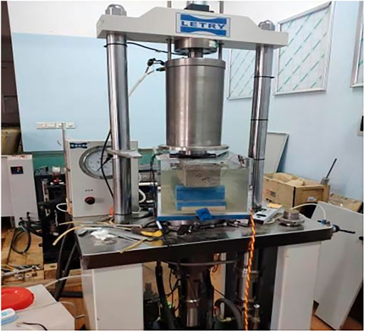
FIGURE 5. Loading device (SDT-50).
The concrete of the tunnel bottom structure is C10, its mix ratios are listed in Table 1. After 28-day standard curing (temperature: 20 ± 2°C, relative humidity ≥95%). The bending strength of the specimens is 5.54 kN (mean value), and the bending strength of the specimens without a cavity is 8.27 kN (mean value), the load-deflection curves of specimens with a base cavity are shown in Figure 6A, Figure 6B is the bending strength of specimens without a base cavity.
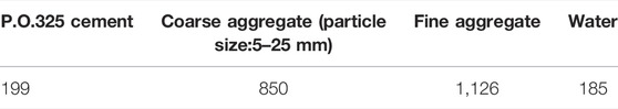
TABLE 1. Mixture ratio of C10 concrete (unit: kg/m³).
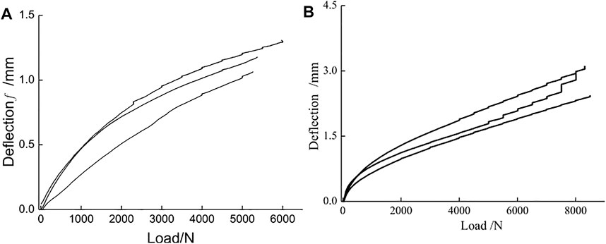
FIGURE 6. Bending strength of specimens. (A) with cavity; (B) without cavity.
The maximum dynamic stress of the tunnel bottom structure emerges when the train passes through, and the corresponding test load is the maximum fatigue load
The fatigue load used in the test is asymmetric sinusoidal cyclic load, frequency is 4 Hz, cyclic load curve is shown in Figure 7. The fatigue load is the vibration amplitude caused by the dynamic train load, and the influence of surrounding rock pressure is not considered in this test.
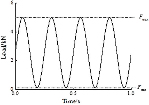
FIGURE 7. Fatigue load.
In order to study the fatigue performance and evolution characteristics of cumulative damage under different load levels (axle load), the test conditions are designed and listed in Table 2. The minimum fatigue load is fixed at 0.1 kN so as to avoid additional impact caused by separation. Three tests are carried out under each test condition.
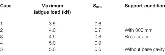
TABLE 2. Tests conditions.
The maximum deflection occurs at the specimen’s mid-span section, and the fatigue crack also emerges at the mid-span section of the specimen. The loading device will record the vertical displacement of the loading point automatically, which can be used as the mid-span deflection of the specimen. The deflection acquisition frequency is 50 Hz The test is stopped when the specimen cracks, and the number of cycles is the fatigue life of the specimen.
In Figure 8A, fatigue characteristics of specimens with a base cavity (case 1–case 4) are similar, the maximum deflection evolution curves are all “S-shaped” and can be divided into three stages, similar to the results of the literature (Oneschkow, 2016). With the increase of the maximum load, the initial deflection increases and the fatigue life decreases.
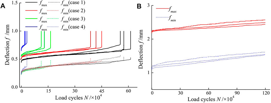
FIGURE 8. Deflection evolution curves. (A) cracked specimen; (B) unbroken specimen.
In Figure 8B, cracks do not occur in the specimen of case 5 after 1.2 × 10⁶ cycles. The deflection characteristic curves of unbroken specimens (case 5) are significantly different from that of the broken specimens (case1–4) and much higher than the broken specimen. The specimens’ fatigue lives of case 5 are obviously larger than the specimens with a base cavity.
The maximum stress level of case 1 and case 5 is 0.6, so the deflection amplitude
where:
where:
The deflection amplitude
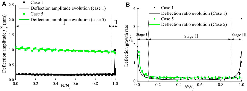
FIGURE 9. Evolution model of deflection. (A) deflection amplitude; (B) deflection growth rate.
Figure 9A reveals that in case 1, the deflection amplitude of the broken specemin develops in 2-stages, it is stable in stage I (N/Nf <0.95), increasing sharply in stage II (0.95≤ N/Nf ≤1.0). In case 5, with the increase of cycles, the deflection amplitude of unbroken specimens decreases slightly and remains stable until the end of loading. It is supposed that the reason for the deflection amplitude decrease is the stiffness regression of the spring in the test.
Figure 9B shows that, in case 1, the deflection growth rate develops quickly in the beginning, then decreases to a certain value when N/Nf reaches about 0.1–0.15, it is stage I. Then the deflection growth rate will keep stable in stage II. Finally, when N/Nf reaches about 0.9–0.95, the deflection growth rate began to accelerate and eventually caused structural failure.
Figure 9B also explained the reason for the rapid increase of deflection in stage I and stage III in Figure 8A. Among them, stage I represents that the initial internal cracks are compacted, so the deflection growth rate decreases with the increase of loading cycles; stage III means the cracks are gradually emerging and expanding until fatigue failure of the structure.
Fatigue damage of concrete structures is often evaluated by elastic modulus (Wei et al., 2003), strain (Oneschkow, 2016), and deflection. The deflection growth is closely related to the nucleation and propagation of fatigue cracks and it reflects the fatigue damage of concrete (Liu et al., 2016). So in this paper, the cumulative fatigue damage
where:
Convert the abscissa to N/Nf in Figure 8, and combined with Eq. 4, the maximum deflection and fatigue damage evolution curves are obtained, shown in Figure 10. The deflection evolution characteristics of case 1–case 4 are all “S-shaped” and the curves can be divided into three stages. Its deflection increases rapidly in stage-I, slowly and linearly in stage-II, and sharply in stage-III, the dividing point between stage-I and stage-II is located at (0.05–0.10) N/Nf, the second dividing point is at (0.90–0.95) N/Nf.
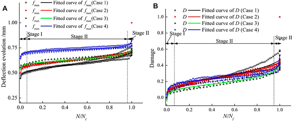
FIGURE 10. Normalized evolution curves. (A) maximum deflection; (B) cumulative damage.
According to the deflection curves in Figure 10, the 3-stage characteristics of the deflection evolution curve can be well described by a normalized fatigue evolution model, shown in Eq. 5.
where:
The parameters of the fatigue cumulative damage evolution model identified for this concrete are given in Table 3. It is supposed that this non-linear relation together with the deflection at the beginning of loading and the deflection at failure might enable the fatigue damage to be estimated.
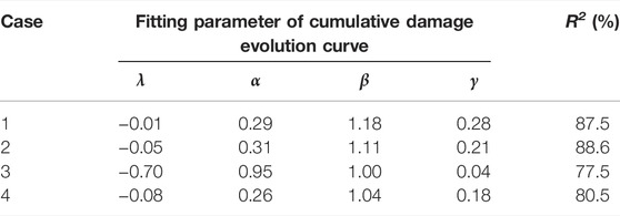
TABLE 3. Parameters of cumulative damage.
The fatigue lives of specimens are listed in Table 4, The S-N curve of the tunnel bottom structure specimens is obtained by fitting the data in Table 4. Figure 11A shows the S-N curves from this study and from literature (Xiao et al., 2013; Li and Che, 1998) under cyclic bending. The expression of the S-N curve is described in Eq. 6, correlation coefficient R2 = 0.90. Similarly, the expression of the f-N relationship is obtained as Eq. 7, the correlation coefficient is 0.96, and the f-N curve is shown in Figure 11B.
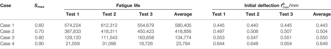
TABLE 4. Fatigue life of specimens.
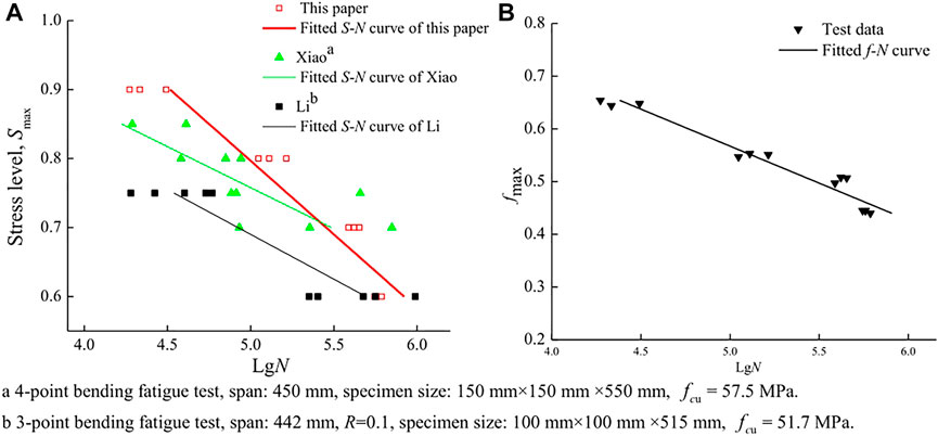
FIGURE 11. Fatigue life curve. (A) S-N curve; (B) f – N curve.
The fatigue life curves reveal that the fatigue life decreases with the increase of stress level and the initial maximum deflection. The strength and span of concrete specimens in this paper are smaller, but the fatigue life is much higher than that in the literature (Li and Che, 1998; Xiao et al., 2013). It can be seen that the larger the base cavity, the lower the fatigue life of the structure.
Based on the typical base diseases in the heavy haul railway tunnel, a series of bending fatigue tests are conducted to investigate the fatigue performance and cumulative damage of the tunnel bottom structure with the base rock cavity. Conclusions are as follows:
1) The evolution curves of maximum deflection and cumulative damage are both s-shaped and the curves can be divided into three stages, the maximum deflection and damage increase quickly in stage-I, steadily and linearly in stage-II, and increase sharply in stage-III until crack.
2) When a cavity exists in the base rock, the damage to the tunnel bottom structure will be accelerated, and the fatigue failure is easier to occur, and the fatigue life of the specimen will decrease with the increase in stress level and cavity width.
3) Under the same load, the base cavity greatly reduces the bearing capacity of the structures, meanwhile improving its maximum stress level, so the tunnel bottom structures’ fatigue performance is reduced remarkably.
4) Based on the test data, the normalized damage evolution model and S-N curve suitable for tunnel bottom structure are obtained, which can provide a reference basis for damage assessment of similar projects.
The original contributions presented in the study are included in the article/Supplementary Material, further inquiries can be directed to the corresponding author.
CL and BW contributed to the conception and design of the study. RL and FW provided the basic data of heavy haul railway diseases and participated in the experimental design and implementation. All authors contributed to manuscript revision, read, and approved the submitted version. Write, CL and BW; Modification, CL, RL, FW, and QT.
This research was funded by the National Science of China (52168055), Natural Science Foundation of Jiangxi Province (20212ACB204001), “Double Thousand Plan” Innovation Leading Talent Project of Jiangxi Province (jxsq2020101001), and Science and Technology Research Project of Jiangxi Provincial Department of Education (GJJ204611).
Authors RL and FW were employed by the company Shuohuang Railway Development Co. Ltd.
The remaining authors declare that the research was conducted in the absence of any commercial or financial relationships that could be construed as a potential conflict of interest.
All claims expressed in this article are solely those of the authors and do not necessarily represent those of their affiliated organizations, or those of the publisher, the editors and the reviewers. Any product that may be evaluated in this article, or claim that may be made by its manufacturer, is not guaranteed or endorsed by the publisher.
Cai, X., Zhong, Y., Hao, X., Zhang, Y., and Cui, R. (2019). Dynamic Behavior of a Polyurethane Foam Solidified Ballasted Track in a Heavy Haul Railway Tunnel. Adv. Struct. Eng. 22 (3), 751–764. doi:10.1177/1369433218799154
Dong, J., Zhong, S., Wang, H. L., and Wu, Z. H. (2020). Dynamic Response Characteristics of Crossing Tunnels under Heavy-Haul Train Loads. Geomech. Eng. 20 (2), 103–112. doi:10.12989/gae.2020.20.2.10310.1061/(asce)gm.1943-5622.0001765
GB/T 50081-2002 (2003). Standard for Test Method of Mechanical Properties on Ordinary Concrete. Beijing, China: China Architecture & Building Press.
Han, J. D., Liu, W. Q., Wang, S. G., Geert, D. S., Sun, W., and Liang, Y. (2017). Carbonation Reaction and Microstructural Changes of Metro-Tunnel Segment Concrete Coupled with Static and Fatigue Load. J. Mater. Civil Eng. 29 (2), 1943–5533. doi:10.1061/(ASCE)MT.1943-5533.0001742
Hu, Y. D. (2015). Current Status and Development Trend of Technology System for Railway Heavy Haul Transport in China. China Railway Sci. 36 (2), 1–10. doi:10.3969/j.issn.1001-4632.2015.02.01
Huang, L. C., Ma, J. J., Lei, M. F., Liu, L. H., Lin, Y. X., and Zhang, Z. Y. (2020). Soil-Water Inrush Induced Shield Tunnel Lining Damage and its Stabilization: A Case Study. Tunn Underground Space Tech. 97 (2020), 103290. doi:10.1016/j.tust.2020.103290
Kim, N. Y., Park, D. H., Jung, H. S., and Kim, M. I. (2020). Deformation Characteristics of Tunnel Bottom after Construction under Geological Conditions of Long-Term Deformation. Geomech. Eng. 21 (2), 171–178. doi:10.12989/gae.2020.21.2.171
Lazorenko, G., Kasprzhitskii, A., Khakiev, Z., and Yavna, V. (2019). Dynamic Behavior and Stability of Soil Foundation in Heavy Haul Railway Tracks: A Review. Construction Building Mater. 205, 111–136. doi:10.1016/j.conbuildmat.2019.01.184
Lei, M. F., Liu, J. Y., Lin, Y. X., and Liu, C. (2019). Deformation Characteristics and Influence Factors of a Shallow Tunnel Excavated in Soft Clay with High Plasticity. Adv. Civ. Eng. 2019, 1–14. doi:10.1155/2019/7483628
Li, Y. Q., and Che, H. M. (1998). A Study on the Cumulative Damage to Plain Concrete Due to Flexural Fatigue. China Railway Sci. 19 (2), 52–59.
Li, Z., Chen, K., Li, Z., Huang, W., and Wang, X. (2021). Deterioration and Cavity of Surrounding Rocks at the Bottom of Tunnel under the Combined Action of Heavy-Haul Load and Groundwater: An Experimental Study, Front. Earth. Sci. 9, 1–9. doi:10.3389/feart.2021.779578
Liu, C., Lei, M.-F., Peng, L.-M., and Shi, C.-H. (2020). Cavity Influence on Fatigue Performance of Heavy Haul Railway Tunnel's Bottom Structure. Construction Building Mater. 251 (ID), 118886. doi:10.1016/j.conbuildmat.2020.118886
Liu, C., Peng, L., Lei, M., Shi, C., and Liu, N. (2019). Fatigue Performance of Tunnel Invert in Newly Designed Heavy Haul Railway Tunnel. Appl. Sci. 95514 (24), 5514–5612. doi:10.3390/app9245514
Liu, N., Peng, L., Shi, C., and Lei, M. (2016). Experimental and Model Study on Dynamic Behaviour and Fatigue Damage of Tunnel Invert. Construction Building Mater. 126, 777–784. doi:10.1016/j.conbuildmat.2016.09.081
Oneschkow, N. (2016). Fatigue Behaviour of High-Strength Concrete with Respect to Strain and Stiffness. Int. J. Fatigue 87, 38–49. doi:10.1016/j.ijfatigue.2016.01.008
Qian, W., Qi, T., Yi, H., Liang, X., Jin, Z., Lei, B., et al. (2019). Evaluation of Structural Fatigue Properties of Metro Tunnel by Model Test under Dynamic Load of High-Speed Railway. Tunnelling Underground Space Tech. 93 (ID), 103099. doi:10.1016/j.tust.2019.103099
Rickstal, F. B. G. V., Gemert, D. A. V., and Bonheure, M. (1999). Fatigue Testing of Traffic Tunnel Panels. J. Perform. Constructed Facil. 13 (4), 152–156. doi:10.1061/(asce)0887-3828(1999)13:4(152)
Tian, B. S. (2015). Operation and Development of Railway Heavy Haul Transport Technology in the World. Roll. Stock 12, 10–19+5. doi:10.3969/j.issn.1002-7602.2015.12.003
Tian, Y. (2014). The Base Treatment Process with Grouting Resin in Datong-Qinhuangdao Railway Tunnels. Paper Collection Of Heavy Haul Railway Transportation Technical Exchange. Beijing: China Railway Society, 363–367. (in Chinese).
Wang, J., Huang, H., Xie, X., and Bobet, A. (2014). Void-Induced Liner Deformation and Stress Redistribution. Tunnelling Underground Space Tech. 40, 263–276. doi:10.1016/j.tust.2013.10.008
Wei, J., Wu, X. H., and Zhao, X. L. (2003). A Damage Model of Concrete under Freeze-Thaw Cycles. J. Wuhan Univ. Technol. 18 (3), 40–42. doi:10.1007/BF02838455
Xiao, J., Li, H., and Yang, Z. (2013). Fatigue Behavior of Recycled Aggregate Concrete under Compression and Bending Cyclic Loadings. Construction Building Mater. 38, 681–688. doi:10.1016/j.conbuildmat.2012.09.024
Yin, C. F., Fu, B. X., and Ma, W. B. (2013). Analysis on Dynamic Stress of Tunnel Structure under Heavy Haul Train. China Railway Sci. 34 (3), 47–52. doi:10.3969/j.issn.1001-4632.2013.03.08
Zhang, X., Zhang, C. P., Min, B., and Xu, Y. J. (2020). Experimental Study on the Mechanical Response and Failure Behavior of Double-Arch Tunnels with Cavities behind the Liner. Geomech. Eng. 20 (5), 399–410. doi:10.12989/gae.2020.20.5.399
Zhang, Z., Zeng, B., Dai, C., and He, W. (2018). Study on Structural Service Performance of Heavy-Haul Railway Tunnel with Voided Base. Adv. Civil Eng. 2018, 1–12. doi:10.1155/2018/3510979
Keywords: tunnel, bottom structure, base cavity, fatigue, damage
Citation: Liu C, Wu B, Li R, Wang F and Tang Q (2022) Fatigue Test on Heavy Haul Railway Tunnel Bottom Structure With Base Cavity. Front. Earth Sci. 10:870710. doi: 10.3389/feart.2022.870710
Received: 07 February 2022; Accepted: 18 March 2022;
Published: 25 April 2022.
Edited by:
Mingfeng Lei, Central South University, ChinaReviewed by:
Qiang Zhang, China Institute of Water Resources and Hydropower Research, ChinaCopyright © 2022 Liu, Wu, Li, Wang and Tang. This is an open-access article distributed under the terms of the Creative Commons Attribution License (CC BY). The use, distribution or reproduction in other forums is permitted, provided the original author(s) and the copyright owner(s) are credited and that the original publication in this journal is cited, in accordance with accepted academic practice. No use, distribution or reproduction is permitted which does not comply with these terms.
*Correspondence: Bo Wu, d3Vib0BlY3V0LmVkdS5jbg==
Disclaimer: All claims expressed in this article are solely those of the authors and do not necessarily represent those of their affiliated organizations, or those of the publisher, the editors and the reviewers. Any product that may be evaluated in this article or claim that may be made by its manufacturer is not guaranteed or endorsed by the publisher.
Research integrity at Frontiers
Learn more about the work of our research integrity team to safeguard the quality of each article we publish.