 Yonghui Huang
 Bo Sun2†
 Zhiyu Zhang
 Jiale Meng
 Hua Zeng
95% of researchers rate our articles as excellent or good
Learn more about the work of our research integrity team to safeguard the quality of each article we publish.
Find out more
ORIGINAL RESEARCH article
Front. Earth Sci. , 25 April 2022
Sec. Geohazards and Georisks
Volume 10 - 2022 | https://doi.org/10.3389/feart.2022.870595
This article is part of the Research Topic Deep Rock Mass Engineering: Excavation, Monitoring, and Control View all 22 articles
Cutting blasting is the principal construction method for roadway and shaft excavation, but the studies on the damage mechanism of cutting blasting affected by the volume effect of empty holes under high ground stress are not insufficient. During cutting blasting, different damage zones are formed. In this paper, combined with the rock damage criterion and RHT constitutive function, the ranges of these damage zones are determined. The smooth particle hydrodynamics method is used to study the influence of high in-situ stress on rock blasting damage from the perspective of the number of empty holes and the production coefficient of rock clamp. The accuracy of the determined damage zone range is verified by supplemented field tests. The research results show that in the process of rock clamp production, the propagation of blasting stress wave is inhibited, especially the tensile stress wave which is more obviously inhibited. The empty holes reduce the inhibitory effect of rock clamp production. With the increase in the production coefficient of rock clip, the blasting damage radius is reduced by 39.7%, 35.1%, 30.5%, 26.7%, and 22.9% compared with the theoretical value, respectively, while its influence on the radius of crushing zone is small. The three-dimensional scanning results were used to inverse calculate the production coefficient of the rock clip. The fitting degree between the numerical simulation and the field test scanning results is about 94.5%, which proves the accuracy of the RHT constitutive parameters and the reliability of the determination range. The mathematical relationship between the production coefficient Kr for rock clip and the relative height H of the wellhead and the area Sc of the cross-section cavity is fitted based on the data of several upward cutting blasting field tests.
At present, in the excavation process of mines, roadways, and shafts, the drilling and blasting method is mainly adopted. With the continuous excavation, the mine and roadway projects are constantly developing deep underground, and the influence of high in-situ stress on construction becomes more significant. The blasting construction under high in-situ stress is mainly affected by the coupling effect of explosion load and in-situ stress field. Therefore, under the condition of ensuring the blasting effect, controlling the damage range of rock mass becomes a further concern (Li et al., 2011; Yao-Ji, Xiao-Shuang, and Wang 2014; Fan et al., 2017; Xie et al., 2018).
For the blasting parameters in cut blasting, a lot of studies have been carried out (Cai et al., 2004; Cheng et al., 2020; K. ; Gao et al., 2021; X.S. ; Li et al., 2021; Man et al., 2018; D.Q. ; Yang, Wang, et al., 2020; H. ; Zhang et al., 2021; X.Y. ; Zhang et al., 2020), but most of them are based on shallow burial depth and only consider blasting load conditions. With the deepening of research, Kaiser, Zou, and Lang (1990) proposed a method taking into account initial stress unloading and stress field, and summarized the determination method for excavation damage area of the tunnel. Besides, L. Xie, Lu, Jiang, et al. (2017); L.X. Xie, Lu, Zhang, et al. (2017) used a numerical simulation method to study the influence of in-situ stress and rock damage inoculation mechanism in the process of deep tunnel cutting blasting and proposed a simplified method for determining blasting load (NDIL). In addition, Q. Li et al. (2016); Q.Y. Li et al. (2018) established the stress state equation of rock mass in the cutting area according to the influence of cutting rock breaking under different stress fields and carried out visual analysis by numerical simulation. The introduction effect of the initial stress field on crack growth and the tensile stress concentration effect of the empty hole was studied. Furthermore, by establishing a damage model under the coupling effect of blasting load and dynamic unloading, and combining the fracture mechanics and rock damage failure criterion, Xiao et al. (2018) calculated the rock stress distribution and fracture characteristics under high in-situ stress conditions. Moreover, Li et al. (2010) introduced the damage variable D into the elastic-plastic constitutive model of FLAC3D numerical software. Through the parameter of rock effective stress, cross-analysis of field blasting vibration monitoring and numerical simulation was performed, and the critical damage vibration velocity was obtained as the safety criterion of blasting damage. Additionally, Wei et al. (2016) established a mechanical model for rock blasting damage and carried out numerical simulation analysis on the crack evolution of slotted cartridge blasting under different in-situ stress conditions. Through these methods, the controlled factors of the crack propagation direction of slotted cartridge under blasting were obtained. What’s more, by using the improved SHPB test, (Z.Q. Yin et al., 2020; Z.Q. Yin et al., 2018; Z.Q. Yin et al., 2014; Z.-q. Yin et al., 2012) and analyzed the fracture mechanical properties of coal seam with gas under coupling load, analyzed the damage of coal seam by observing the changes of stress, strain, and energy dissipation, which provides a theoretical basis for the design of deep mining support with gas. Differently, D. Yang et al. (2014) used the finite difference method to study the damage distribution of the rock surrounding the tunnel under the combined action of blasting load and dynamic unloading of in-situ stress and analyzed the influence of damage range from lateral pressure coefficient, unloading rate and mechanical properties of the rock mass. Further, based on the theory of cylindrical cartridge blasting funnel, Jun and Qihu (2007) established a criterion of collapse blasting standard funnel under high in-situ stress and proposed the calculation formula for roadway collapse blasting parameters. According to the SPH-FEM coupling method, J. Yang, Wu, et al., 2020; J. Yang, Sun, et al., 2020) studied the influence of in-situ stress field on seismic wave energy in rock blasting fragmentation areas and outside the fragmentation area. It is concluded that the in-situ stress field has an inhibitory effect on blasting fragmentation and affects the propagation of blasting seismic waves. Du, Li, Tao, et al. (2020), Du et al. (2021), Du, Li, Yang, et al. (2020) obtained the conclusion that the fatigue failure of rocks within the biaxial stress boundary is related to the peak level of fatigue load, the magnitude of intermediate principal stress and lithology through biaxial compression test and biaxial fatigue test on the fracture characteristics of marble and sandstone. The rock-breaking efficiency under fatigue load is higher, but it is also easier to induce severe hard rockburst disasters. Apart from the above studies, through numerical simulation, X.J. Yang et al. (2020) studied the influence of in-situ stress on roadway deformation, and obtained that directional blasting can play a role of pressure relief by changing the structure of surrounding rock and control the deformation of the roadway. Further, J. Gao et al. (2020) analyzed the blasting effects of different blasting delays and charge hole diameters under high in-situ stress conditions and obtained the evolution law of crack propagation in cutting blasting under in-situ stress and different lateral pressure coefficients. S. Wang et al. (2021), S.F. Wang et al. (2019) studied rock machinability by using the rock crushing test under true triaxial loading. The rock machinability was analyzed by the biaxial confining pressure, uniaxial cutting force, and the penetration depth under the initial fracture and complete fracture of the specimen, and a series of measures to improve the machinability were proposed, which provided suitable conditions for mechanized mining in hard rock. To sum up, the researches on cutting blasting under high in-situ stress are relatively limited, and most of the models used in numerical simulation adopted RHT damage constitutive model. However, there is a lack of in-depth study on the rock damage partition of this constitutive model in numerical simulation, thus it is necessary to establish the blasting damage partition in RHT constitutive model.
At present, the Dahongshan Iron Mine in Yunnan requires a large amount of blind shaft construction, and the construction mainly adopts the one-time deep hole blasting well completion technology of upward blind shaft, of which the key point is the cutting blasting, and the general situation of field construction is shown in Figure 1.
FIGURE 1. Site construction conditions.
Therefore, in this paper, the cutting effect of different hole layout methods is explored and using the smooth particle hydrodynamics method, the calculation formula of rock damage partition in RHT constitutive is proposed based on the RHT damage constitutive model and rock damage variable partition. By applying stress to simulate the rock clamp production in cutting blasting, and supplemented field tests, the feasibility of RHT damage partition and simulation clamp production is verified. Through the three-dimensional scanning of the cavity area, the production coefficient of the rock clamp is inversely deduced, and the mathematical relationship between the production coefficient of the rock clamp and the relative height of the wellhead and the section cavity area is fitted, which provides theoretical guidance for the analysis of the fracture zone and the design of blasting parameters in deep cutting blasting.
In the numerical simulation, the RHT damage constitutive proposed by Riedel, Hiermaier, and Thoma in 1997 is selected. The relationship between the elastic limit strain, material failure strength, residual strength, and hydrostatic pressure is described by introducing the elastic limit surface, failure strength surface, and residual strength surface (Riedel, Kawai, and Kondo 2009).
The damage factor D in the RHT constitutive model is defined as:
Which:
where, Δɛp is the equivalent plastic strain increment; εpf is the final failure equivalent plastic strain; ɛpm is the minimum equivalent plastic strain when the material is damaged; D1 and D2 are the initial damage parameter and the complete damage parameter, respectively.
For p∗, pt∗ in materials, Eqs 4, 5 are usually used:
where, p is the pressure on the material, MPa; fc is the uniaxial compressive strength of rock, MPa; Fr is a dynamic strain rate increment factor; Q0 is the initial meridian ratio parameter; fs∗ and ft∗ are shear-compression strength ratio and tensile-compression strength ratio, respectively; B represents the Rode angle parameters.
The increment factor of dynamic strain rate is related to the material strain rate and shear strength, and the expression is:
The elastic limit surface in RHT constitutive should be set by the elastic limit surface equation and the 'cap function' of the elastic limit stress overflow of the constraint material under high hydrostatic pressure. The elastic limit surface equation is:
Where Fe is the elastic scaling function, and the expression is:
where, Fc is the cap function, which is introduced to reduce the volume expansion caused by shear stress and limit the elastic limit stress of materials under high hydrostatic pressure. The expression is:
Qin et al. (2021) studied the damage failure behavior of rock materials according to the existing research results of rock damage variable D and the damage failure criterion of rock materials. The damage value corresponding to the peak strength of rock materials is regarded as the rock critical damage parameter Dcr, and the material failure is mainly caused by the plastic deformation of materials. Therefore, the relationship between the rock plastic strain and rock critical damage parameter can be expressed by Eq. 10:
In order to establish the mathematical relationship between the critical damage parameters of rock in the RHT constitutive model and the parameters in the model, the RHT constitutive function is sorted out according to Eq. 10. Therefore, the plastic strain and ultimate strain in Eq. 10 can be sorted as:
The rock damage and fragmentation thresholds Dcr and Dcf are evaluated by the stress pel at the beginning of rock crushing and the stress pcomp at rock compaction, respectively. Therefore, Eqs 11, 12 can be transformed into:
The lithology of the tested rock is sodium metamorphosed lava, and the parameters of its RHT constitutive model can be obtained by related mechanical tests and theoretical calculations, as shown in Table 1.
TABLE 1. RHT constitutive parameters.
By substituting the determined RHT constitutive parameters of sodium metamorphosed lava into Eqs 13, 14, the obtained critical damage parameter Dcr = 0.11 and the rock fragmentation threshold Dcf = 0.51, which are used as the criteria for rock damage and fragmentation in subsequent numerical simulations.
In this cutting blasting, the initial rock damage D1, explosive quantity Q, and initial propagation frequency f0 are regarded as constant, thus there is a certain relationship between rock damage D and blasting center distance r:
Order
Combining Eqs 15, 16, the relationship curve between the detonation center distance r and damage variable D can be obtained:
where, the attenuation coefficients a1 and a2, blasting initial frequency f0 can refer to previous research, and the blasting data fit that a1 = 7.8 × 10⁻³, a2 = 9.5 × 10⁻⁴, f0 = 47 Hz. Therefore, combined with the previously determined critical rock damage threshold Dcr and rock fragmentation threshold Dcf, the blasting damage zones in cut blasting are obtained (Table 2):
TABLE 2. Damage subarea of rock under blasting load.
In the table: rc, rd, ro are the critical blast center distance of fragmentation zone, critical blast center distance of damage zone, and critical blast center distance of original rock vibration zone respectively, in m.
Explosives use the ANN-2 viscous ammonium nitrate explosive provided by mines, and the explosive parameters are shown in Table 3. The explosives used in the numerical simulation are implemented by keyword ∗ MAT_HIGH_EXPLOSIVE_BURN. JWL equation of state to introduce the description of volume, pressure, and energy variation characteristics of explosive production during the explosion. The expression equation is as follows Eq. 18:

TABLE 3. ANN-2 Viscous ammonium nitrate explosive parameters.
The parameters of the explosive and JWL state equation can be determined by fitting experimental data, as shown in Table 3.
The upward cutting blasting test project of Yunnan Dahongshan Iron Mine is taken as the research object in this paper. The test is expected to form a blind shaft of 2 m × 2 m through a well completion blasting, and the upward cutting blasting test is the preparatory work for the well completion blasting, of which the purpose is to select the best cutting hole arrangement method. Herein, the quasi-three-dimensional model with unit thickness is selected to explore the blasting effect. In order to eliminate the boundary effect, the model size is set as 6 m × 6 m × 0.01 m. The drilling equipment provided by the mine isa D421 car and T150 drilling rig, which carries a 50 mm drilling bit, 152 mm, and 203 mm expanding bit. Therefore, in the numerical simulation, the empty hole radius R1 = 0.1 m, the charging hole radius R2 = 0.05 m, and the hole spacing d = 0.35 m. The LS-DYNA finite element software is used in the numerical model, and the SPH method is used to replace the finite element to smooth particles. Fixed constraints are applied at the bottom of the model, and compressive stresses are applied in the other three directions to simulate the rock clamp production. The cutting geometry model with a different number of holes is shown in Figures 2A–E, and the numerical model of cut blasting with a scheme (e) as an example is shown in Figure 2F.
FIGURE 2. (A–E) Geometric model and (F) numerical model.
In order to study the influence of the empty hole compensation effect on the cutting blasting effect for rock clip production, numerical simulations were carried out on the above schemes. The coefficient Kr for different rock clip production was simulated by changing the applied stress, and the simulation results were analyzed by the post-processing software LS-Prepost.
It can be seen from Figure 3A that when the in-situ stress is not considered, under the action of explosion stress wave and the stress introduction of the empty hole, the rock fragmentation is first concentrated in the rock between the empty hole and the charge hole. Figure 3B is the blasting effect of rock clip with 1.0. The fragmentation of rock between the empty hole is slightly delayed, and the empty hole plays a certain role in hindering the propagation of explosion stress wave, thus the pressure on the rock outside the empty hole is reduced. The range of rock fracture is smaller than that of the space hole. However, due to the introduction effect of the empty hole on the blasting stress wave, the range of rock damage at the center of the empty hole and the charge hole is wider. The main tensile cracks are more obviously concentrated outside the empty hole, and the number of empty holes is more. The formation and development of micro-splitting cracks outside the rock damage area under the action of blasting gas are more significant. Therefore, it can be speculated that the introduction effect of the empty hole on the blasting stress wave is beneficial to the formation and development of rock cracks after blasting, and the compensation effect of the empty hole can improve the cavity-forming effect and the rock damage range. However, after applying the rock clamping stress, the damage range of the rock is significantly reduced. The influence of the compressive stress on the outer side of the empty hole inhibits the initiation and propagation of tensile cracks under blasting. Therefore, no obvious main cracks are formed, thus the blasting generated explosive gas reduces the efficiency of rock splitting, and only short cracks are formed around the empty hole wall.
FIGURE 3. Numerical Simulation Process: (A) No in-situ stress condition; (B) Kr = 1.0.
To explore the influence of rock clip production on the cutting blasting effect and damage range of rock, the cavity area Sc and rock damage range Sd were delineated according to the previously determined damage zoning variables.
It can be seen from the amplification of the blasting effect position that with the increase of the production coefficient of the rock clip, the inhibitory effect of compressive stress on the formation of the main tensile crack outside the empty hole gradually increases, and the crack initiation phenomenon outside the rock crushing zone gradually disappears, and the crack propagation phenomenon in the direction of the empty hole diameter significantly disappears. When the production coefficient of the rock clip is 2.0, only very small damage is initiated outside the rock crushing zone, and no crack is formed. The damage range of rock near the empty hole is significantly reduced under the influence of compressive stress. The mechanism of the inhibition for the propagation of stress wave by the rock outside the empty hole is analyzed under the coupling effect of the attenuation of blast stress wave and the production of rock clip. The energy reaching here cannot break the rock or cause large damage. Through the coordinate output of the area near the blasting and the area delineation, the statistics of the cutting blasting area carried out by scheme (e) are shown in Figure 4.
FIGURE 4. Calibration of blasting damage area.
Figures 5A–D show the variation trends of the cavity area Sc, rock damage range Sd and stress of rock outside the hole after each cutting blasting under different production forces of rock clip. It can be found that with the increase of hole number, Sc and Sd show an increasing trend. The main reasons are the compensation effect and stress concentration effect provided by holes, which enhance the blasting failure effect and improve the crushing effect of cavity rock. After applying the stress conditions, Sc and Sd show a decreasing change with the increase of the coefficient Kr of rock clip production.
FIGURE 5. Numerical simulation blasting effect curve: (A) Slot cavity curve; (B) Damage area curve; (C) Peak pressure curve; (D) Blasting center distance curve.
As can be seen from Figures 5C, D, due to the inhibitory effect of rock clip force on blasting stress wave and the dispersion and coupling effect of empty holes on blasting stress wave, the pressure P on the outer side of the empty hole and the blasting center distance r show a nonlinear downward trend, with the increase of empty hole number and the production coefficient of rock clip. When the production coefficient of rock clips are between 0 and 1, the influence of blasting changes greatly, but the overall change is small. It can be speculated that the rock clamping force mainly affects the range of rock damage zone by inhibiting the initiation and propagation of blasting cracks, but it has little inhibitory effect on the blasting effect of the rock crushing zone. Combined with the data in Figures 5D, 6, it can be seen that the greater the number of empty holes, the less the blasting inhibitory effect of rock clamp production, and the inhibitory effect is most significant in the direction of the connection between the empty holes and charge holes.
FIGURE 6. Numerical simulation of cutting blasting with different rock clamping coefficients: (A) Kr = 0, (B) Kr = 0.5, (C) Kr = 1.0, (D) Kr = 1.5, and (E) Kr = 2.0.
The study of the influence law of rock clamp production on cutting blasting provides a theoretical reference for the determination of cutting blasting test parameters under deep ground pressure. According to the data in Figure 5D, the relationship curve between the radius of crushing zone rc and the coefficient Kr of rock clamp production (later called rc-Kr curve ) is obtained, and the rc-Kr curve is:
In the field test of cut blasting, the determination method of rock fracture zone radius is:
Tang, Zhou, and Liao (2015) established a reliable rock damage zoning for underground engineering construction blasting, and the damage variable of the fracture zone is:
Therefore, the rock fragmentation damage value Dfrag can be obtained by the Eqs. 20, 21:
The field test adopts the six-hole cutting form for construction. The DL421 trolley is used to cooperate with the T150 drilling rig, and the error of the drilling operation is controlled within the allowable range. The data are provided by the mine geological exploration department. The buried depth of the test area is about 640 m, and the horizontal in-situ stress is about 18.4 MPa, thus the production coefficient of the rock clamp is about 1.01. It can be observed that from the orifice to the bottom of the cavity, the increase of rock clamp production leads to a decrease of the cavity area. Figure 7A–C are the field blasting effect diagram.
Figure 7D shows the comparison of the scanning area and the simulation area of the cutting wellhead section, and their values are 0.441 and 0.435 m2, respectively, with a fitting degree of 98.6%. According to the three-dimensional scanning results, the radius of the crushing zone is counted, and the production coefficient for the rock clip is inversely deduced in combination with Eq. 22, to carry out a numerical simulation on the cutting section at different depths. The area comparison at different depths is shown in Figure 8, and the overall fitting degree is 94.5%, which proves the reliability of the numerical simulation inversion method and the feasibility of the RHT fracture criterion.
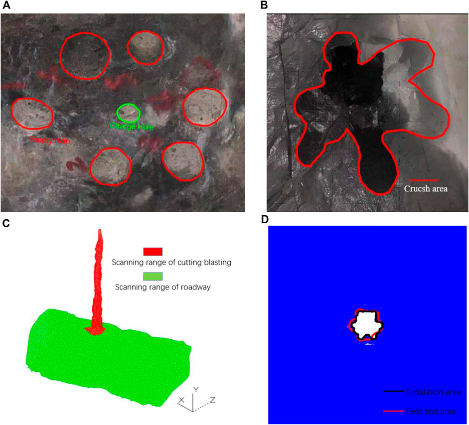
FIGURE 7. 1#Field test results and verification:(A) Blasthole construction drawing; (B) Cutting blasting effect; (C) scanning results; (D) Numerical simulation and field scanning comparison.
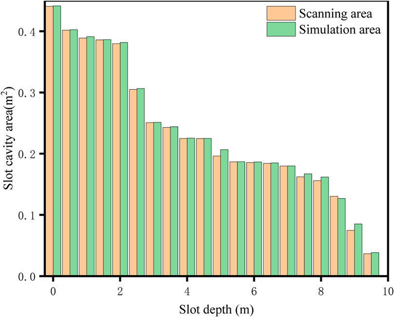
FIGURE 8. Reliability comparison between numerical simulation effect and field scanning result.
Several groups of upward cutting blasting tests are carried out, and the cavity area after blasting is scanned by three-dimensional laser scanning. The cavity area under different depths in the test is simulated by the numerical simulation inversion method. The drilling construction in the upward cutting blasting site and the effect of the wellhead section after blasting are shown in Figure 9.
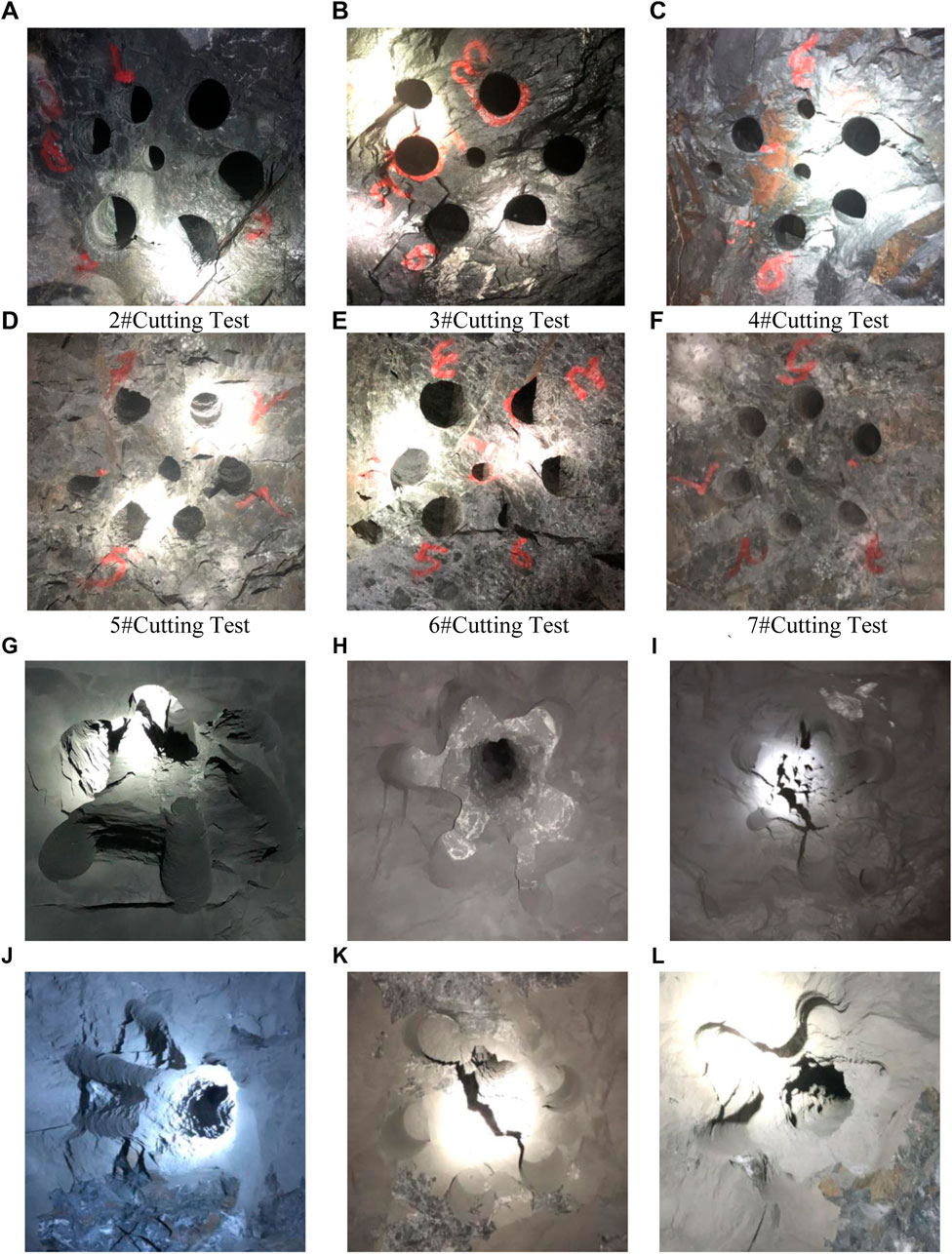
FIGURE 9. (A)10 m Cutting drilling (B)∼(C)15 m Cutting drilling (D–F)20 m Cutting drilling (G–L) 1–6#Test blasting effect.
It can be observed from the blasting effect that the rock between the charge hole and the 6 # empty hole has not penetrated due to the long distance of the 6 # empty hole in the second group of 15 m. The cavity formation at the wellhead of the cutting blasting test in other groups is satisfying, and the expected blasting effect is achieved. Then, a three-dimensional laser scanner was used to scan the cut blasting cavity. Due to the large depth of the cavity in the test and the limitation of the scanning instrument, the cut blasting cavity of 15 and 20 m was scanned every 1 m, and then the area of the section cavity was inversely calculated by numerical simulation. The inversed numerical results were compared with the field three-dimensional scanning results, as shown in Figure 10.
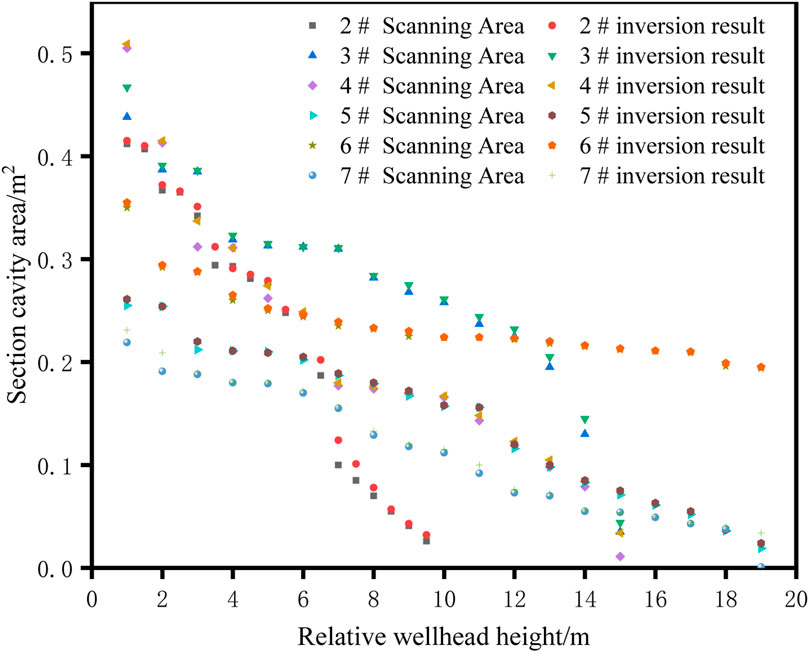
FIGURE 10. Comparison of field scanning results and numerical inversion results.
When the wellhead relative height is in the range of 0–0.5 m, the charge hole in this section is mainly filled with mud, and the numerical inversion is mainly based on the application of blasting load. Therefore, the Numerical backstepping analysis will be carried out from the wellhead relative height of 1 m. The production coefficient statistics of rock clips are carried out by combining the follow-up numerical simulation inversion data with the previous inversion data, and the variation law between Sc-Kr-H is analyzed. Eqs. 23, 24 show the mathematical relationship between the coefficient Kr for rock clip production and the relative height of the wellhead H and the cavity area Sc of the cut blasting section respectively. The variation law is shown in Figure 11.
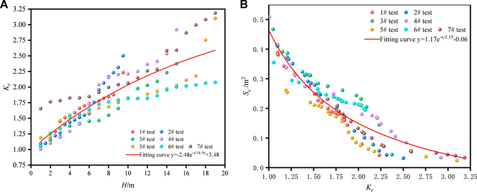
FIGURE 11. (A) Kr-H optimal curve (B)Sc-Kr optimal curve.
In this paper, aiming at the lack of research on blasting damage partition of RHT damage constitutive in numerical simulation, the rock clip production in cutting blasting was simulated, and the cutting mode and rock clip coefficient of a different number of empty holes were numerically studied. The following conclusions are obtained:
1) Based on the rock critical damage threshold equation, the blasting rock breaking strain mechanism, and the RHT constitutive embedded function, the blasting damage zoning range in numerical simulation is deduced. According to the filed test, the mechanical parameters of variable sodium lava are obtained, and the range of different damage zones in numerical simulation is determined.
2) The rock damage area caused by blasting attenuates to a certain extent after applying the rock clip, and the initiation and propagation of tensile cracks are also inhibited. The larger the coefficient of rock clip, the more obvious the suppression effect of the blasting tensile effect. Compared with the splitting effect, the blasting crushing area is less affected. The empty holes provide a certain compensation space for cutting blasting, and the stress concentration of empty holes enhances the blasting effect. The empty holes also reduce the inhibitory effect of rock clip production on blasting damage. The rock damage area is mainly concentrated in the direction of the maximum principal stress, and the tensile failure is mainly near the empty hole. With the increase of rock clip production, the tensile stress decreases, indicating that rock clip production mainly affects the range of rock damage by inhibiting the propagation of tensile stress.
3) According to the comparative analysis of field test results and numerical simulation results, the fitting degree of numerical simulation is high. Therefore, it is proved that the stress application method and the constitutive parameters of RHT have certain accuracy. The production coefficient of rock clip at different depths is inversely calculated by using the three-dimensional laser scanning results. The data showed that the fitting degree of comparison is 94.5%, indicating that the divided RHT damage zoning determination range has certain reliability. Combined with multiple sets of test field scanning data, the blasting effect of the cut section is inversely calculated, and the mathematical relationship between the production coefficient Kr of rock clip and the relative height of wellhead H and the section cavity area Sc is fitted, which provides theoretical guidance for the design of cutting blasting and one-time well completion blasting parameters under the condition of high in-situ stress.
The original contributions presented in the study are included in the article/Supplementary Material, further inquiries can be directed to the corresponding author.
Conceptualization, methodology, software, validation, formal analysis, writing-original draft, writing-review and editing: BS; Investigation, data curation: JM, HZ; Supervision, software: YH; Funding acquisition, project administration Resources, investigation: ZZ.
This research is supported by financial grants from the National Natural Science Foundation of China (52064025, 52164009, 52164010). The authors are very grateful to the financial contribution and convey their appreciation to the organization for supporting this basic research.
The authors declare that the research was conducted in the absence of any commercial or financial relationships that could be construed as a potential conflict of interest.
All claims expressed in this article are solely those of the authors and do not necessarily represent those of their affiliated organizations, or those of the publisher, the editors and the reviewers. Any product that may be evaluated in this article, or claim that may be made by its manufacturer, is not guaranteed or endorsed by the publisher.
Cai, M., Kaiser, P. K., Tasaka, Y., Maejima, T., Morioka, H., and Minami, M. (2004). Generalized Crack Initiation and Crack Damage Stress Thresholds of Brittle Rock Masses Near Underground Excavations. Int. J. Rock Mech. Mining Sci. 41 (5), 833–847. doi:10.1016/j.ijrmms.2004.02.001
Cheng, B., Wang, H. B., Zong, Q., Xu, Y., Wang, M. X., Zheng, Q. Q., et al. (20202020). A Study on Cut Blasting with Large Diameter Charges in Hard Rock Roadways. Adv. Civil Eng. doi:10.1155/2020/8873412
Du, K., Li, X., Tao, M., and Wang, S. (2020). Experimental Study on Acoustic Emission (AE) Characteristics and Crack Classification during Rock Fracture in Several Basic Lab Tests. Int. J. Rock Mech. Mining Sci. 133. doi:10.1016/j.ijrmms.2020.104411
Du, K., Li, X., Wang, S., Tao, M., Li, G., and Wang, S. (2021). Compression-shear Failure Properties and Acoustic Emission (AE) Characteristics of Rocks in Variable Angle Shear and Direct Shear Tests. Measurement 183. doi:10.1016/j.measurement.2021.109814
Du, K., LiLi, X.-f., YangYang, C.-z., Zhou, J., Chen, S.-j., and Manoj, K. (2020). Experimental Investigations on Mechanical Performance of Rocks under Fatigue Loads and Biaxial Confinements. J. Cent. South. Univ. 27 (10), 2985–2998. doi:10.1007/s11771-020-4523-7
Fan, Y., Lu, W., Zhou, Y., Zhao, C., and Peng, Y. (2017). Evolution Mechanism of Damage Zone in Surrounding Rock Mass during Excavation of Deep Tunnels under High Geostress Condition. J. Eng. Geology. 25 (2), 308–316.
Gao, J., Xie, S. Z., Zhang, X. T., Wang, H. L., Gao, W. L., and Zhou, H. M. (2020). Study on the 2D Optimization Simulation of Complex Five-Hole Cutting Blasting under Different Lateral Pressure Coefficients. Complexity 2020. doi:10.1155/2020/4639518
Gao, K., Huang, P., Liu, Z. G., Liu, J., Wang, F., and Shu, C. M. (2021). Pressure Relief by Blasting Roof Cutting in Close Seam Group Mining under Thick Sandstone to Enhance Gas Extraction for Mining Safety. Processes 9 (4). doi:10.3390/pr9040603
Jun, D. A. I., and Qian, Q. (2007). Break Blasting Parameters for Driving a Roadway in Rock with High Residual Stress. Explosion and Shock Waves 27 (3), 272–277.
Kaiser, P. K., Zou, D., and Lang, P. A. (1990). Stress Determination by Back-Analysis of Excavation-Induced Stress Changes ? a Case Study. Rock Mech. Rock Engng 23 (3), 185–200. doi:10.1007/bf01022953
Li, Q., Huang, W., Wu, Z., Kong, D., and Liu, K. (2016). Theoretical Study and Numerical Simulation on Rock Failure Process in Cutting by Parallel Hole under Different Ground Stress Conditions. J. Saf. Sci. Tech. 12 (11), 57–62.
Li, Q.-y., Liu, K., Li, X.-b., Wang, Z.-w., and Weng, L. (2018). Cutting Parameter Optimization for One-step Shaft Excavation Technique Based on Parallel Cutting Method. Trans. Nonferrous Met. Soc. China 28 (7), 1413–1423. doi:10.1016/s1003-6326(18)64780-6
Li, X., Chen, J., Li, Y., and Dai, Y. (2010). Study of Criterion and Damage Zone Induced by Excavation Blasting of Underground Power-House of Xiluodu Hydropower Station. Chin. J. Rock Mech. Eng. 29 (10), 2042–2049.
Li, X., Yao, J., and Gong, F. (2011). Dynamic Problems in Deep Exploitation of Hard Rock Metal Mines. Chin. J. Nonferrous Met. 21 (10), 2551–2563. doi:10.1016/s1003-6326(11)60720-6
Li, X. S., Peng, K., Peng, J., and Hou, D. (2021). Effect of thermal Damage on Mechanical Behavior of a fine-grained sandstone. Arabian J. Geosciences 14 (13). doi:10.1007/s12517-021-07607-0
Man, K., Liu, X. L., Wang, J., and Wang, X. Y. (20182018). Blasting Energy Analysis of the Different Cutting Methods. Shock and Vibration, 13. doi:10.1155/2018/9419018
Qin, Q., Li, K., Li, M., and Liu, B. (2021). Study on Damage Failure Criterion and Failure Behavior of Non-homogeneous Rock Materials. Chin. J. Rock Mech. Eng. 40 (9), 1812–1825.
Riedel, W., Kawai, N., and Kondo, K.-i. (2009). Numerical Assessment for Impact Strength Measurements in concrete Materials. Int. J. Impact Eng. 36 (2), 283–293. doi:10.1016/j.ijimpeng.2007.12.012
Tang, H., Zhou, Y., and Liao, Y. (2015). Damage Zone of Surrounding Rock of Underground Engineering under Construction Blasting. J. Vibration Shock 34 (23), 202–206.
Wang, S., Sun, L., Li, X., Wang, S., Du, K., Xiang, L., et al. (2021). Experimental Investigation of Cuttability Improvement for Hard Rock Fragmentation Using Conical Cutter. Int. J. Geomechanics 21 (2). doi:10.1061/(asce)gm.1943-5622.0001899
Wang, S. F., Li, X. B., Yao, J. R., Gong, F. Q., Li, X., Du, K., et al. (2019). Experimental Investigation of Rock Breakage by a Conical Pick and its Application to Non-explosive Mechanized Mining in Deep Hard Rock. Int. J. Rock Mech. Mining Sci. 122. doi:10.1016/j.ijrmms.2019.104063
Wei, C., Zhu, W., Yu, B., and Niu, L. (2016). Numerical Simulation on Cutting Seam Cartridge Blasting under Different In-Situ Stress Conditions. Explosion and Shock Waves 36 (2), 161–169.
Xiao, S., Jiang, Y., Liu, Z., and Su, L. (2018). Hard Rock Blasting Energy Distribution and Fragmentation Characteristics under High Earth Stress. J. Vibration Shock 37 (15), 143–149.
Xie, L., Lu, W., Jiang, Q., Zhang, Q., Wang, G., Chen, M., et al. (2017). Damage Evolution Mechanism of Deep Rock Mass in Process of Cut Blasting. J. Cent. South Univ. Sci. Tech. 48 (5), 1252–1260.
Xie, L.-T., Yan, P., Lu, W.-B., Chen, M., and Wang, G.-H. (2018). Effects of Strain Energy Adjustment: A Case Study of Rock Failure Modes during Deep Tunnel Excavation with Different Methods. KSCE J. Civ Eng. 22 (10), 4143–4154. doi:10.1007/s12205-018-0424-9
Xie, L. X., Lu, W. B., Zhang, Q. B., Jiang, Q. H., Chen, M., and Zhao, J. (2017). Analysis of Damage Mechanisms and Optimization of Cut Blasting Design under High In-Situ Stresses. Tunnelling Underground Space Tech. 66, 19–33. doi:10.1016/j.tust.2017.03.009
Yang, D., Li, H., Xia, X., and Luo, C. (2014). Study of Blasting-Induced Dynamic Damage of Tunnel Surrounding Rocks under High In-Situ Stress. Rock Soil Mech. 35 (4), 1110.
Yang, D. Q., Wang, X. G., Wang, Y. J., An, H. M., and Lei, Z. (20202020). Experiment and Analysis of Wedge Cutting Angle on Cutting Effect. Adv. Civil Eng. doi:10.1155/2020/5126790
Yang, J., Sun, W., Yao, C., and Zhang, X. (2020). Mechanism of Rock Fragmentation by Multi-Hole Blasting in Highly-Stressed Rock Masses. Explosion and Shock Waves 40 (7).
Yang, J., Wu, Z., Yao, C., Jiang, S., and Jiang, Q. (2020). Influences of In-Situ Stress on Blast-Induced Rock Fracture and Seismic Waves. J. Vibration Shock 39 (13), 64.
Yang, X. J., Liu, C. K., Sun, H. L., Yue, S. L., Ji, Y. G., Zhang, X. Y., et al. (2020). Researchonthe Deformation Mechanism and Directional Blasting Roof Cutting Control Measures of a Deep Buried High-Stress Roadway. Shock and Vibration. doi:10.1155/2020/6742504
Yao-Ji, L. I., Xiao-Shuang, L. I., and Wang, M. L. (2014). Progress of Research on Mining Technology for Transition from Open-Pit to Underground Mine of Gently Inclined,thin and Medium Thick Phosphate Rocks. Ind. Minerals Process.
Yin, Z.-q., Li, X.-b., Jin, J.-f., He, X.-q., and Du, K. (2012). Failure Characteristics of High Stress Rock Induced by Impact Disturbance under Confining Pressure Unloading. Trans. Nonferrous Met. Soc. China 22 (1), 175–184. doi:10.1016/s1003-6326(11)61158-8
Yin, Z., Chen, W., Hao, H., Chang, J., Zhao, G., Chen, Z., et al. (2020). Dynamic Compressive Test of Gas-Containing Coal Using a Modified Split Hopkinson Pressure Bar System. Rock Mech. Rock Eng. 53 (2), 815–829. doi:10.1007/s00603-019-01955-w
Yin, Z. Q., Hu, Z. X., Wei, Z. D., Zhao, G. M., Ma, H. F., Zhuo, Z., et al. (20182018). Assessment of Blasting-Induced Ground Vibration in an Open-Pit Mine under Different Rock Properties. Adv. Civil Eng. doi:10.1155/2018/4603687
Yin, Z. Q., Ma, H. F., Ma, H. F., Hu, Z. X., and Zou, Y. (2014). Effect of Static - Dynamic Coupling Loading on Fracture Toughness and Failure Characteristics in Marble. Jestr 7 (2), 169–174. doi:10.25103/jestr.072.25
Zhang, H., Li, T. C., Du, Y. T., Zhu, Q. W., and Zhang, X. T. (2021). Theoretical and Numerical Investigation of Deep-Hole Cut Blasting Based on Cavity Cutting and Fragment Throwing. Tunnelling Underground Space Tech. 111, 18. doi:10.1016/j.tust.2021.103854
Keywords: numerical simulation, rock damage, cutting blasting, RHT constitutive model, high in-situ stress, clamp production
Citation: Huang Y, Sun B, Zhang Z, Meng J and Zeng H (2022) Study on the Influence of Rock Clip Production and Empty Hole Volume Effect of Upward Blind Shaft Blasting. Front. Earth Sci. 10:870595. doi: 10.3389/feart.2022.870595
Received: 07 February 2022; Accepted: 24 March 2022;
Published: 25 April 2022.
Edited by:
Kun Du, Central South University, ChinaReviewed by:
Fuqiong Huang, China Earthquake Networks Center, ChinaCopyright © 2022 Huang, Sun, Zhang, Meng and Zeng. This is an open-access article distributed under the terms of the Creative Commons Attribution License (CC BY). The use, distribution or reproduction in other forums is permitted, provided the original author(s) and the copyright owner(s) are credited and that the original publication in this journal is cited, in accordance with accepted academic practice. No use, distribution or reproduction is permitted which does not comply with these terms.
*Correspondence: Zhiyu Zhang, MTEzMDEwNTJAa3VzdC5lZHUuY24=
†These authors share first authorship
Disclaimer: All claims expressed in this article are solely those of the authors and do not necessarily represent those of their affiliated organizations, or those of the publisher, the editors and the reviewers. Any product that may be evaluated in this article or claim that may be made by its manufacturer is not guaranteed or endorsed by the publisher.
Research integrity at Frontiers
Learn more about the work of our research integrity team to safeguard the quality of each article we publish.