 Zhanzhao Li1
 Tinghui Wan1*Yanjiang Yu1,2
 Qianyong Liang1,2Hongfeng Lu1,2Jingli Wang1Lieyu Tian1Huice He1Keliang Li1,2Haijun Qiu1,2*
- 1Guangzhou Marine Geological Survey, Guangzhou, China
- 2Southern Marine Science and Engineering Guangdong Laboratory, Guangzhou, China
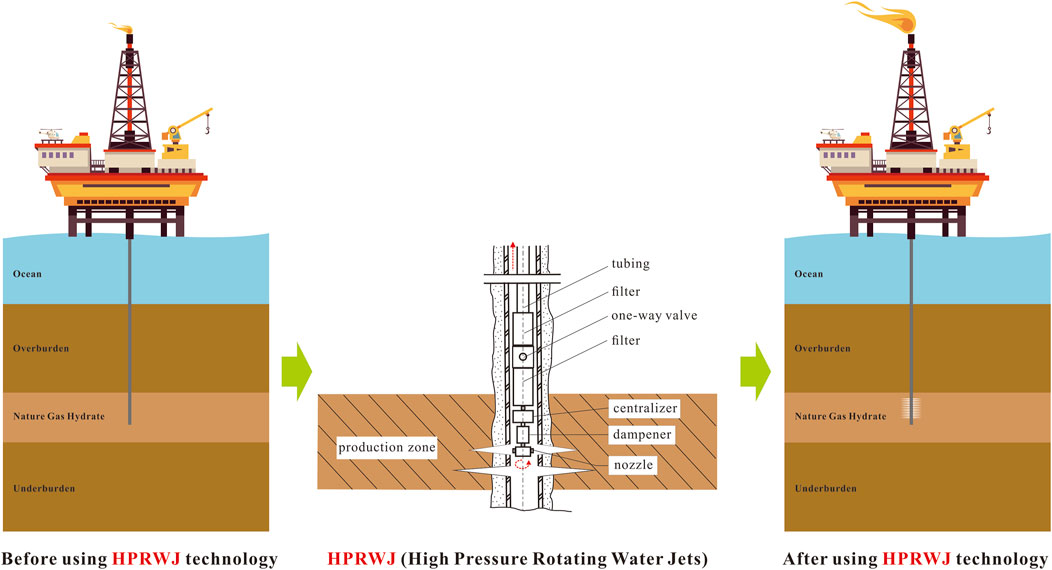
Over 90% of the global hydrate resources are stored in very-low-permeability clayey silt reservoirs. The low permeability significantly restricts the efficiency of gas and water flow into the production well. To enhance gas production efficiency in low-permeability hydrate reservoirs, the high-pressure rotating water jets (HPRWJ) technology is proposed to construct near wellbore artificial fractures (NWAFs) in hydrate reservoirs. The HPRWJ avoid the risks of hydraulic fracturing as well as large-scale reservoir damage, which makes it more suitable for constructing fractures in hydrate-bearing sediments (HBS). In this article, the site SH7 in the South China Sea is studied to evaluate the feasibility of this technology for enhancing gas production of low-permeability hydrate reservoirs by numerical simulation. The results show that the gas productivity is increased by approximately three times by using the HPRWJ technology to construct NWAFs with a depth of 3 m. It is suggested that the proposed technology is a promising method for improving gas production from the low-permeability hydrate reservoirs. Furthermore, the gas production performance is closely related to NWAF depth, NWAF permeability, and NWAF spacing. For the site SH7 in the South China Sea, the NWAF depth, permeability, and spacing are recommended as 3 m, 3D, and 3 m, respectively.
Introduction
The energy demand is growing continually with the development of a global economy (Aydin et al., 2016). According to the International Energy Outlook et al., 2011 of the U.S. Energy Information Administration, the global energy demand will increase by 50% by 2050 and the most energy demand must be satisfied by renewable energy and natural gas (The U.S. Energy Information Administration, 2019). Natural gas hydrates (NGHs) are white, cage-shaped, crystalline solids composed of water and gas molecules, mainly methane, that widely occur in the permafrost and deep oceanic sediments at high pressure and low temperature (Sloan et al., 2008; Su et al., 2011; Sun et al., 2012; Qorbani et al., 2017). The global survey has proved that there is a large quantity of hydrate-bound natural gas that is mainly stored in marine sediments (Moridis and Sloan, 2007c). As a kind of clean and high-energy density resources, the NGHs are considered as a potential resource to meet the rapidly escalating global energy demand.
To harvest natural gas, NGHs have to be converted in situ to free gas. Several production methods have been proposed, such as depressurization (Yuan et al., 2017; Myshakin et al., 2018; Lei et al., 2022), thermal injection (Chong et al., 2016; Yu et al., 2019), gas replacement (Koh et al., 2016; Rossi et al., 2018), and inhibitor injection (Sun Y. et al., 2019; Mu and von solms, 2020). All these methods have been successfully conducted in field trial tests. For example, inhibitor injection was tried in the development of the Messoyakha gas hydrate field (Makogon and Omelchenko, 2013). The test results showed that depressurization is the most economical and effective method for exploiting gas from NGH reservoirs (Hancock et al., 2005; Yamamoto and Dallimore, 2008a; The Ignik Sikumi Gas Hydrate Exchange Trial Project Team, 2012). Therefore, four offshore gas production tests have been conducted using the depressurization method in the Eastern Nankai Trough and the South China Sea. However, the highest daily gas production was only 2.87 × 10⁴ m3. (Li et al., 2018; Ye et al., 2020). Therefore, the improvement of gas production efficiency is still a challenge for NGH exploitation because of the current low efficiency.
The key factors affecting gas production efficiency have been widely investigated. Wang et al. (2013) and Konno et al. (2014) analyzed the effect of production pressure on gas production and concluded that a larger volume of gas could be produced at a lower well pressure. Moridis et al. (2007b) investigated formation property factors affecting gas production and revealed that reservoir permeability was a very important factor controlling hydrate dissociation and gas production and that a lower reservoir permeability was associated with a lower gas production efficiency. However, oceanic NGH in clayey silt sediments with a potential development value have low porosity and poor original effective permeability because the pores are filled with solid hydrates (Fujii et al., 2015; Huang et al., 2015; Yoneda et al., 2017). Although the initial permeability of sediments at site SH7 of the Shenhu area in the South China Sea is 7.5–10–14 m2, the effective permeability is only approximately 1.0 × 10⁻¹⁴ m2 when the NGH pore fill is 40%, according to the relationship between porosity and permeability (Moridis et al., 2008). This will greatly restrict the transfer of pressure and heat between the production wells and the strata, which decreases the production efficiency of the decomposed gas and the dissociation continuity of NGH. Unfortunately, more than 90% of the global NGH is located in the clayey silt sediments with very low permeability (Boswell and Collett, 2011). Therefore, it is important to improve the gas production efficiency from low-permeability clayey silt sediments.
To promote the hydrate production performance, various methods have been investigated through numerical simulation, including well heating and hot water injection combined with depressurization, but the enhancement of gas production is limited (Su et al., 2012; Su et al., 2013). For example, using the well heating method, via heating a production well can only affect the dissociation reaction in the vicinity of the production well. In addition, the hot water injection method cannot transfer injected hot water very far from the well due to the low permeability of reservoirs (Feng et al., 2019b). Although, the horizontal well can dramatically increase the gas production rates, the high operating costs and technical difficulty restrict its large-scale application (Feng et al., 2019a; Yuan et al., 2021b).
In recent years, the enhancement of gas production based on large-scale fractures constructed by hydraulic fracturing technology has been investigated through numerical simulations. For example, Chen et al. carried out the study on depressurization efficiency of a hydraulic fractured NGH reservoir, in which the fracture depth was 40 m (Chen et al., 2017). Feng et al. evaluated the efficacy of the combination of hydraulic fractures and depressurization and constructed an elliptic hydraulic fractured zone in an NGH reservoir, and the corresponding semi-major axis and semi-mini axis were 50 and 20 m respectively (Feng et al., 2019b). The simulation results indicated that the large-scale hydraulic fractures can greatly improve the CH4 gas production rates during the depressurization process in the hydrate reservoir.
However, there are some challenges for the practical application of hydraulic fracturing technology in marine NGH reservoirs. The main challenges are as follows: (1) Marine NGH reservoirs are normally buried in the shallow seabed and the unconsolidated hydrate-bearing sediments exhibiting limited shear strength, especially after the hydrates have dissociated. (2) The NGH reservoirs are significantly thin. (3) There are distinct differences in the breakdown pressure between hydrate-bearing sediments and non-hydrate-bearing sediments, which are more than 10 MPa and less than 1 MPa, respectively (Too J. L. et al., 2018; Too J. L. et al., 2018). (4) The directivity, depth, and height of the fractures constructed by hydraulic fracturing are hard to control in unconsolidated sediments. As a result, high-pressure fracturing fluids (10 MPa) are liable to move through the non-hydrate-bearing overburden once the fluids break through hydrate-bearing sediments during hydraulic fracturing. Therefore, fractures that cut-through hydrate-bearing sediments and the seafloor are liable to form, causing environmental unfriendly gas seepages, uncontrolled dissociations, or blowouts (Koh et al., 2016). Moreover, the large-scale deep (tens, even hundreds of meters) fractures constructed by hydraulic fracturing technology destroy the structural stability of hydrate-bearing sediments (HBS), which is adverse to the long-term economic and feasible gas production from marine NGH reservoirs (Goto et al., 2016; Kim et al., 2016).
To solve the aforementioned challenges when exploiting gas from low-permeability clayey silt NGH reservoirs, the authors proposed the strategy of adopting the HPRWJ technology to construct NWAFs in order to improve the permeability of near wellbore reservoirs. The HPRWJ technology is widely used in conventional oil and gas reservoirs to enhance production. When constructing fractures using this method, high-pressure water (or water with added sand, expansion inhibitor, or clay stabilizers) is injected through a rotating nozzle to generate jets to penetrate into reservoirs, ultimately forming cylindrical jet artificial fractures around the wellbore (Li et al., 2002). As a result, NWAFs, whose depth is an order lower than that of the large-scale deep hydraulic fracturing fractures, are formed and the permeability of near wellbore reservoirs is distinctly improved. While constructing fractures, the jet pressure, rotary speed, processing interval, and processing time can be selected and controlled according to geological conditions, which means the fracture position, depth, and spacing are easy to control. While avoiding the risks of hydraulic fracturing, the NWAFs constructed by the HPRWJ technology have the following advantages: (1) The fracture position, spacing, and depth are easy to control. (2) The fractures are not likely to create large-scale reservoir damage. (3) Compared with hydraulic fractures, NWAFs can extremely maintain the stability of the hydrate reservoir. These advantages are beneficial to the long-term stable and economic exploitation of marine NGH reservoirs. Creating NWAFs using the HPRWJ technology is more feasible than the hydraulic fracturing fractures in marine NGH reservoirs. Moreover, the formation of hydrates in a sediment-hosted pore space increases the mechanical strength of the host sediments, making some of its physical and mechanical properties close to those of semi-consolidated marine sediments and increasing the feasibility of creating artificial fractures in NGH reservoirs. The feasibility has been reported by Konno et al. (2016) who found that the permeability of NGH-bearing sand was increased by fracturing and was maintained even after re-confining and closing the fractures. In addition, Too J. L. et al. (2018) and Too J. L. et al. (2018) examined the susceptibility of HBS with high saturation to fracture, and constructed artificial fractures. Therefore, creating NWAFs using the HPRWJ technology before gas production by depressurization is feasible and this work provides an alternative approach to produce gas more effectively from low-permeability clayey silt NGH reservoirs.
Based on low-permeability clayey silt NGH reservoirs in the South China Sea, the authors constructed a series of reservoir models with NWAFs to investigate the feasibility of the proposed strategy. Specifically, a depressurization vertical well was used to conduct our study, because it is the most practical and economical method for large-scale and long-term exploitation of marine NGH reservoirs. Furthermore, the effects of the factors of NWAFs such as depth, permeability, and spacing on the gas production performance were also tested in detail. This work may suggest an advantage reference for improving gas production efficiency from low-permeability clayey silt NGH reservoirs in the future.
Materials and Equipment
Completion of NWAFs in HBS
As shown in Figure 1, the HPRWJ tool consists of filters, a one-way valve, centralizer, rotation controller, and self-oscillation nozzles. While constructing NWAFs using the HPRWJ technology, the tool is lowered into the borehole at the perforation intervals using the connecting tubing. Then, high-pressure clean water (or water with added sands, expansion inhibitor, or clay stabilizers) is pumped through the tubing, filters, one-way valve, and nozzles to generate jets. Simultaneously, the nozzles are rotated by the rotation controller and the rotary speed is adjusted by the dampener. The impurities in the perforations become loose and will be removed with the back flow under repeated jet impacts. Then axisymmetric cylindrical artificial fractures are obtained near the wellbore in the selected position. The tool is able to move up and down to the next position by the draw work of the tubing. Therefore, a series of axisymmetric cylindrical artificial fractures are obtained very easily. Furthermore, fracture shapes can be kept by adding sand to the jet water or replacing the jet water with coagulable and permeable grouting mixtures (Yuan et al., 2021a; Li et al., 2021). This article focuses on the impacts of NWAFs on the hydrate production performance, the geomechanical effect on fractures’ permeability, and the geomechanical response associated with the fractures that are not considered during gas production. However, the geomechanical effect and response will be further investigated.
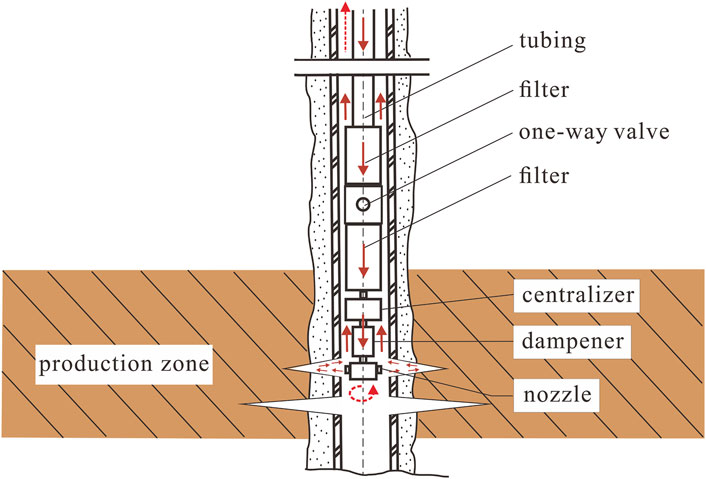
FIGURE 1. Schematic of bottomhole assembly of the high-pressure rotating water jets tool.
Methods
Background
The Shenhu Area is the first NGH reservoir exploited in China. It is located in the middle part of the northern slope between the Xisha Trough and the Dongsha Islands in the South China Sea (Figure 2) (Wu et al., 2011). During GMGS-1 in 2007, three of the five sites (sites: SH2, SH3, and SH7) cored in this area were detected of having high concentrations of NGH. The thickness of the hydrate-bearing sediments (HBS) is 10–43 m and the bottom of the HBS is situated directly above the base of the gas hydrate stability zone, which is suitable for exploitation (Wang et al., 2011). Core sampling and well logging analysis of the SH7 site indicated that the NGH exist at depths of 155–177 m below the seabed, with a water depth of 1,108 m. The sediment porosity and NGH saturation are 33–48% and 20–44%, respectively (Li et al., 2011a). The overburden and underburden layers are similar to HBS but lack of hydrates sedimentary. In situ measurements show that the bottom temperature is approximately 3.7°C with a geothermal gradient of 43.3°C∙km−1. The main component of the gas is methane (96.10%–99.91%), with other gases mainly consisting of C2H6 and C3H8. In addition, the sediments are mainly composed of silty clay and clay silt with a millidarcy-range intrinsic permeability.
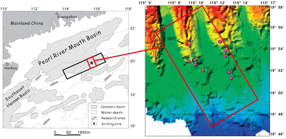
FIGURE 2. Location of the Shenhu area, South China Sea (Wu et al., 2011).
Numerical Simulation Code
In this study, the TOUGH + HYDRATE V1.5 software was used to investigate the effects of NWAFs on the gas production of NGH reservoirs (Moridis, 2014). The accuracy of this software has been tested by massive studies at different hydrate sites around the world. The following assumptions were made when using this simulator (Moridis, 2014): (1) Darcy’s law is valid in the model domain, (2) the mechanical dispersion of dissolved gases and inhibitors is ignored, (3) the movement of the geologic medium is not described, (4) the aqueous phase is not allowed to disappear when salts are present, (5) the dissolved inhibitors do not affect the thermophysical properties of the aqueous phase, and (6) the inhibitor is a non-volatile component. The governing equations for its multiphase flow and heat convection and conduction processes are given as follows.
1) Components and phases:
Four phases, namely, solid-hydrate (H), aqueous (A), gaseous (G), and ice (I) phases are continuously distributed in the pore of HBS. The four components, including water (w), methane (m), hydrate (h), and salt (i), are partitioned among four possible phases. For simplicity, the κ and β indicators are used in the subsequent equations to define these components and phases, respectively.
According to the thermodynamic state of HBS, the quantity of formed hydrate or the quantity of released methane gas is determined by the following reaction:
2) Mass balance:
The governing equation for the flow of multicomponent fluid mixtures determined based on the mass balance is as follows:
where Mκ, Fκ, and qκ are the mass accumulation, flux, and source/sink ratio of component κ, respectively.
The mass accumulation term Mκ is determined by
The mass flux term Fκ includes the contribution from the aqueous and gaseous phases and the equation is as follows:
For the aqueous phase,
For the gaseous phase,
The diffusive mass flux of component κ (κ = m,i) is calculated using Fick’s law. It is defined as
3) Energy balance:
The governing equation for the heat flow determined based on the energy balance is as follows:
where θ denotes the heat component and Mθ, Fθ, and qθ are the heat accumulation, flux, and source/sink ratio, respectively.
The heat accumulation term includes contributions from the rock matrix and all the phases, and the equation is as follows:
The heat flux term includes conduction and advection, and the equation is as follows:
Reaction heat Qd of hydrate dissociation is calculated by
Model Construction
This study investigated the stimulated production performance with special emphasis placed on NWAFs and compared these results with the production potential determined using a conventional vertical well. To this end, two different cases were defined as follows:
1) Case 1: gas production using conventional vertical well design, as shown in Figure 3B.
2) Case 2: gas extraction using a vertical well with NWAFs, as shown in Figure 3C.
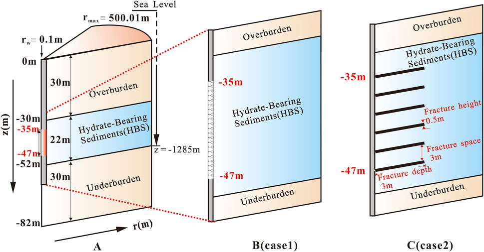
FIGURE 3. Schematic of hydrate reservoir at site SH-7, schematic of hydrate reservoir (A), conventional vertical well (B), vertical well with NWAFs (C).
According to Li et al. (2002), when using the HPRWJ technology to construct NWAFs, the impact pressure, which is the pressure that the jet impacts at the sediment surface, will increase linearly with the increase of pump pressure, and the impact pressure is about 80–90% of pump pressure. Under the pump pressure of 20 MPa, the fracture’s depth and height in the consolidated sediment can be up to 1 m, 500 mm respectively and the impact pressures still reach 3.0 MPa when the radial distance increases up to 1 m. Moreover, the maximum pump pressure can reach 50 MPa, which means the jet impacting distance can reaches far more than 1 m. Otherwise, according to the study conducted by Burland (1990) and Wei et al. (2021), the shear strength of hydrate-bearing sediments and consolidated sediments is 0.5 MPa and more than 5 MPa, respectively. The bulk modulus and mechanical strength of HBS are both much lower than those of the consolidated sediment. Therefore, it is easier to create NWAFs in HBS. In this article, the fracture depth, height, and spacing in HBS is assumed to be 3 m, 500 mm, and 3 m, respectively, as shown in Figure 3C.
Figure 3A shows the schematic of the NGH reservoir model used in this study, which was established based on the SH7 site in the Shenhu area. According to the previous research results from Li Gang et al. at this site, an axisymmetric cylinder with a radius of 500.1 m and a thickness of 82 m was employed to denote the model domain, which consisted of one HBS area, one permeable top layer (the overburden), and one permeable bottom layer (the underburden), whose thickness was 22, 30 and 30 m along the vertical direction, respectively (Li et al., 2011b). According to previous studies of Moridis and Kowalsky (2007a) and Moridis et al. (2007b), the overburden and underburden layers with a thickness of 30 m each were sufficient to simulate the heat and pressure transfer during gas production.
Additionally, the inner and outer boundaries are also very important for gas production prediction (Sun X. et al., 2019). The production well with a radius of rw = 0.1 m was located in the center of the cylinder. The perforated interval was 12 m long and located in the middle part of the HBS which can prevent free water in the overburden and underburden layers from entering into the wellbore at the beginning of the simulation (Su et al., 2010). The bottomhole pressure was set to 4.5 MPa which is similar to the field test condition in the Nankai Trough (Yamamoto and Dallimore, 2008b; Fujii et al., 2013). The top and bottom boundaries were set to boundaries with constant temperature and pressure. Meanwhile, the outside of the model (rmax = 500.01 m, the thinkness of 0.01 m improves the boundary definition accurate) was treated as a boundary where no exchange of heat and flow occurred. The wellbore porosity, permeability, and capillary pressure are assumed to be 1.0, 5.0 × 10⁻⁹ m2 and 0 respectively, treated as a pseudo-medium (Moridis and Reagan, 2011). Meanwhile, fractures were all assigned the same values except for the permeability. Based on the experiments performed by Liu et al. (2012) to analyze the effects of the width, generation method, and filled material of an artificial fracture on its permeability, the authors obtained the permeability of the fractures (≈3.0 × 10⁻¹² m2). While constructing NWAF using the HPRWJ technology, the tool is able to move up and down very slowly at a constant speed with a unaltered nozzle rotate speed at a fixed pump pressure, and thus, the fracture is assumed to be a thin rectangular-shape as show in Figure 3C.
Domain Discretization
Figure 4 shows the schematic of the meshes used to predict the gas production from the HBS under two different conditions (i.e., cases 1 and 2). The model domain was discretized using a cylindrical coordinate system, producing 99 (in r direction) × 102 (in z-direction) = 10098 grids, including 9,876 active elements and 222 boundary elements located on the top, bottom, and inner portion of the model. In the r direction, the first grid (Δr = 0.10 m) represents the wellbore; a fine discretization (Δr = 0.25 m) was applied from the second to sixth grid; the grid size increases exponentially from the 7th to 98th grid; and the 99th grid acts as the outermost boundary. Since hydrate exploitation is a complicated process with heat and mass transfer, the grid blocks near the wellbore are relatively dense in order to accurately describe the change in the physical properties of the hydrates (Moridis and Sloan, 2007c). In the z direction, two thin layers (Δz = 0.01 m) are used to define the uppermost and lowermost boundaries; a sparse discretization (Δz = 1 m) was applied to the overburden and the underburden to improve the computational efficiency owing to the lack of hydrates in these layers; a fine discretization (Δz = 0.5 m) was applied in the HBS in order to accurately describe the physical properties of the hydrates during exploitation. Since four equations were calculated for each grid block, 39,504 (= 9876 × 4) equations were calculated in the whole simulation system in total.
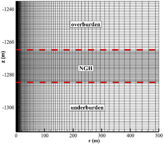
FIGURE 4. Schematic of model discretization.
Initial Conditions
The main parameters of the model were set based on the core samples’ analyses and well logs in this region (Li et al., 2013; Liang et al., 2014). The sediment porosity and permeability were set to 0.4 and 7.5 × 10⁻¹⁴ m2, respectively. The overburden and the underburden were fully saturated with water and the hydrate saturation of the HBS was set to 0.44. The capillary pressure model (e.g., the van Genuchten function) and the three-phase relative permeability model (e.g., the modified version of Stone’s function) were employed. They are commonly used in numerical simulations and have been validated by field hydrate production tests (Anderson et al., 2011; Moridis and Reagan, 2011). The corresponding parameters of these multiphase flow models were determined using the accessible data in the literature. The lateral-to-vertical permeability ratio (kR/kZ) of HBS and the overburden and underburden layers were set to 4.0 according to the latest pressure core flood test (Yoneda et al., 2019). The system parameters and physical properties of the simulation are given in Table 1. It should be noted that the initial conditions in the whole reservoir would remain stable unless there was a disturbance from outside, such as depressurization or thermal injection.
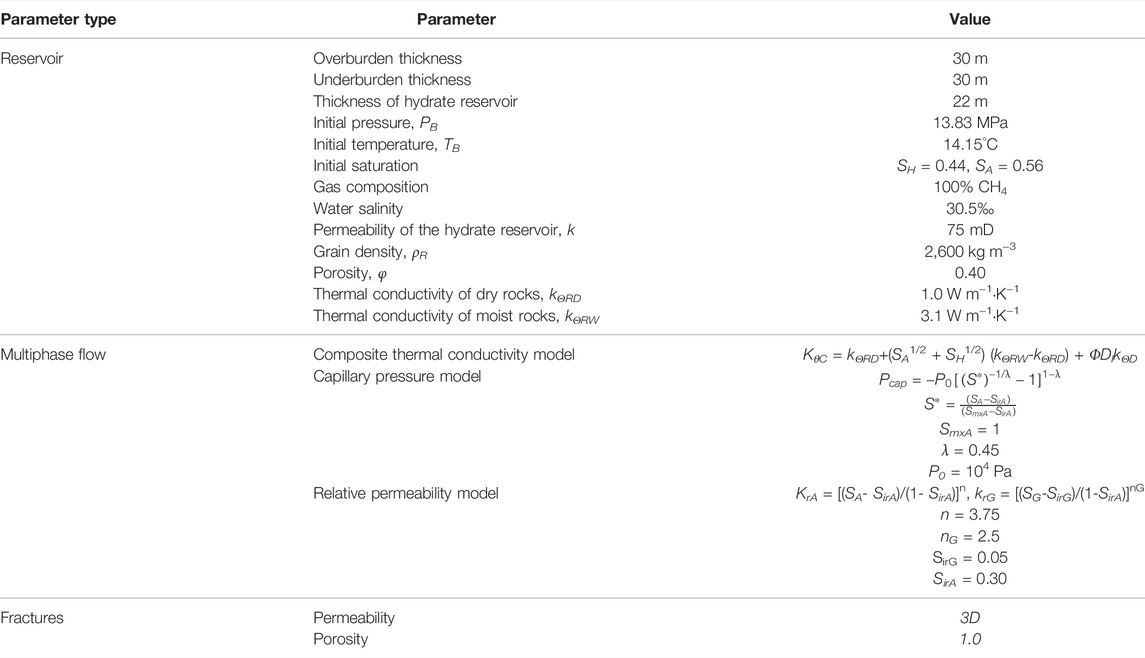
TABLE 1. Main properties and parameters used in the hydrate reservoir model.
Results
Gas and Water Production Behaviors
The production performance of the two cases, including gas production rate (QT), cumulative gas production (VT), cumulative water production (VW), and gas-water ratio (RGW), in 1 year are shown in Figures 5, 6, respectively.

FIGURE 5. Time-varying curve of QTcase1, QTcase2, VTcase1, and VTcase2.
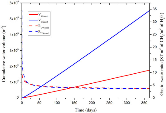
FIGURE 6. Time-varying curve of VWcase1, VWcase2, RGWcase1, and RGWcase2.
In case 2, the gas production rate and cumulative gas production (QT and VT) were consistently over 6000 ST m3/d and up to 230 × 104 ST m3 respectively. In case 1, they were 2000 ST m3/d and 75 × 104 ST m3, respectively. These findings indicate that the hydrate reservoir productivity increased by about three times when NWAFs were constructed by the HPRWJ technology. Therefore, this technology is a promising method for improving the gas production of low-permeability hydrate reservoirs.
There are three main reasons that the HPRWJ technology promotes hydrate productivity. Firstly, high-conductivity fractures with certain morphologies can be created near the production well, thus increasing reservoir permeability and dramatically decreasing flow resistance around the production well. As a result, the efficiency of gas and water flow towards the production well can be improved. Secondly, the effective surface area for the discharge of water and gas can be increased. The effective surface area only includes the surface area of the wellbore in case 1, while it includes the surface area of the wellbore and the artificial fractures and thus increased by several times in case 2; as a result, in case 2, there was more flux at the same production pressure. Thirdly, NWAFs can enlarge the transfer distance of pressure drops, as shown in Figure 7A, and can correspondingly accelerate hydrate dissociation, as shown in Figure 7B, thus increasing the gas production rate of hydrate reservoirs.
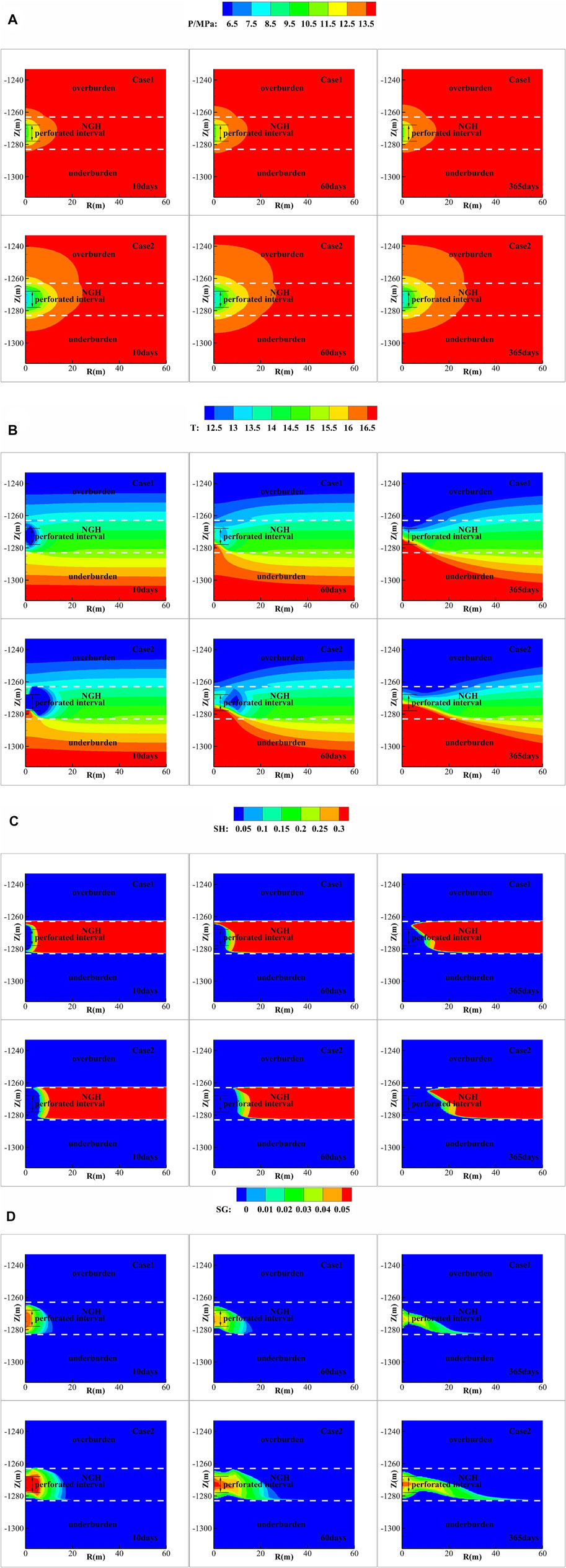
FIGURE 7. Spatial distribution of pressure MPa (A), temperature °C (B), hydrate saturation (C), and gas saturation (D) after 10, 60, and 365 days after and before reservoir stimulation.
During the simulated 1-year production period, the cumulative water production (VW) and the gas–water ratio (RGW) in case 2 were 55 × 104 m3 and 3.7 respectively, and those in case 1 were 17.5 × 10⁴ m3 and 3.7 respectively. These numbers indicate that, in case 2, not only gas production, but also water production increased, whereas the gas–water ratio was hardly affected. Therefore, it is necessary to optimize the perforated interval before NWAFs are constructed in order to achieve the optimal gas–water ratio.
Law of Change in Physical Properties
Analyzing the changes in the main physical properties of hydrate reservoirs helps to understand the characteristics of hydrate dissociation and the processes of gas and water production during NGH exploitation. The spatial distributions of the pressure, temperature, hydrate saturation, and gas saturation in case 1 and 2 after 10, 60, and 365 days are shown in Figures 7A–D, respectively.
As shown in Figures 7A,C, in case 2, the transfer distance of the pressure drop during the whole exploitation was about 30 m, which was two-fold larger than that in case 1. The hydrate dissociation range was also distinctly larger in case 2, which is the major reason why the gas production rate in case 2 was three times that of case 1 as shown in Figure 5. However, in both cases, there was no significant changes in the transfer range of the pressure drop in the early (60th day) and later stages (365th day) of gas production. This consistency was mainly due to the fact that both the overburden and the underburden layers were composed of permeable sediments, and the water in these sediments can flow into the production well after a certain period of time. As a result, the pressure drop failed to be transferred into the deep reservoir, which restricted the hydrate dissociation to some extent. Therefore, to improve the recovery of the entire hydrate reservoir, well spacing should be properly controlled when vertical wells are employed to exploit hydrate deposits with permeable boundaries.
As an endothermic reaction, hydrate dissociation consumes the heat of the surrounding areas while producing gas and water, thus affecting the temperature distribution of the hydrate reservoir. Figure 7B clearly shows that there was an obvious low-temperature area near the production well at the start stage of NGH exploitation (10 days) and that the low-temperature area in case 2 was significantly greater than that in case 1. These findings are consistent with the hydrate dissociation ranges shown in Figure 7C. Figure 7B also demonstrates that, in both cases, the low-temperature area gradually shrunk at the early and later stages of NGH exploitation (the 60th and 365th day, respectively). This occurred mainly because the water from the overburden and the underburden flowed into the production well, changing the temperature distribution of the hydrate reservoir around the well. In particular, the hot water in the underburden significantly heated the hydrate reservoir and promoted hydrate dissociation. This phenomenon is consistent with the morphology of the hydrate dissociation front illustrated in Figure 7C.
The gas released from the hydrate dissociation was either extracted from the hydrate reservoir or remained in it as free hydrocarbon gas. Figure 7D shows that the gas-bearing area in case 2 was significantly larger than that in case 1, which indirectly proves that NWAFs can effectively promote the dissociation of hydrates into gas and water.
Discussion
Effects of Fracture Parameters on the Gas Productivity of the Hydrate Reservoir
This article aims to apply the HPRWJ technology to vertical wells. The parameters used in this technology (e.g., jet pressure, rotary speed, processing time, and the moving distance of the tubing) determine the key fracture parameters, such as fracture depth, permeability, and spacing. Therefore, the effects of the key parameters of NWAFs on gas productivity were discussed, which is very important for parameter selection when using the HPRWJ technology for constructing NWAFs. The relationships between HPRWJ parameters and NWAF parameters will be further investigated through a laboratory and numerical study.
Effects of Fracture Depth on Gas Productivity
Fractures' depth is mainly controlled by jet pressure, rotary speed, and processing time. To compare the effects of different NWAF depths on the gas productivity of hydrate deposits, NWAF depths were set to 1, 2, 3, 4, and 5 m, as shown in Table 2. The authors assumed that fracture permeability, fracture spacing, fracture height, and the length of the completion interval were 3 D, 3, 0.5, and 12 m, respectively.
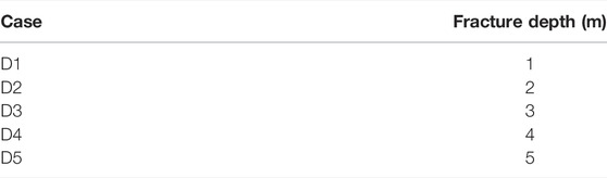
TABLE 2. Fracture depth and corresponding calculation case.
Figures 8, 9 present the gas production rate (QTD), cumulative gas production (VTD), cumulative water production (VWD), and gas–water ratio (RGWD) at different NWAF depths. When the fracture depth increased from 1 to 2, 3, 4, and 5 m, the VTD increased from 1.54×10⁶ ST m3 to 1.91×10⁶ ST m3, 2.30×10⁶ ST m3, 2.49×10⁶ ST m3, and 2.73×10⁶ ST m3 respectively, increasing by 24.0, 49.3, 61.7, and 77.3%. The results indicate that the gas production rate increases with an increase in the NWAF depth. However, VTD increased by 8.3% when the fracture depth increased from 3 to 4 m, and by 20.4% when the fracture depth increased from 2 to 3 m. This indicates that the increase in fracture depth corresponds with the decrease in the magnitude of gas production efficiency. Therefore, a fracture depth of 3 m is recommended for the low-permeability hydrate reservoirs at site SH7. Moreover, it has been observed that cumulative water production increases as the NWAF depth increases, and that fracture depth has no effect on the gas–water ratio.
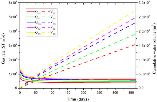
FIGURE 8. Time-varying curve of gas production rate (QTD) and cumulative gas production (VTD) in case of different fracture depths.
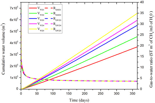
FIGURE 9. Time-varying curve of cumulative water production (VWD) and gas–water ratio (RGWD) in case of different fracture depths.
Effects of Fracture Permeability on Gas Productivity
According to laboratory test results, fracture permeability is closely related to the materials added to jet water and can reach 7.45×10² D during NWAF construction (Xu et al., 2016). To compare the effects of different NWAF permeability values on the productivity of hydrate deposits, NWAF permeability was set to 1 D, 2 D, 3 D, 4 D, and 5 D, as shown in Table 3. The authors assumed that fracture depth, fracture spacing, fracture height, and the length of the completion interval were 3, 3, 0.5, and 12 m, respectively.
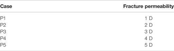
TABLE 3. Fracture permeability and corresponding calculation case.
Figures 10, 11 present the gas production rate (QTP), cumulative gas production (VTP), cumulative water production (VWP), and gas–water ratio (RGWP) in cases of different NWAF permeability values. When fracture permeability increased from 1 D to 2 D, 3 D, 4 D, and 5 D, VTP increased from 1.57×10⁶ ST m3 to 2.03×10⁶ ST m3, 2.30×10⁶ ST m3, 2.49×10⁶ ST m3, and 2.62×10⁶ ST m3, respectively, increasing by 29.3, 46.5, 58.6, and 66.9%, respectively. The results indicate that the gas production rate increases with an increase in the NWAF permeability. However, VTP increased by 8.3% when fracture permeability increased from 3 D to 4 D, and by 13.3% when the fracture permeability increased from 2 D to 3 D. This illustrates that the increase in fracture permeability corresponds with the decrease in the magnitude of gas production efficiency. Therefore, fracture permeability of 3 D is recommended for the low-permeability hydrate reservoirs at site SH7. Moreover, cumulative water production increases as the NWAF permeability increases, and fracture permeability has no effect on the gas–water ratio.
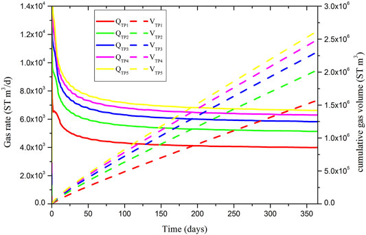
FIGURE 10. Time-varying curve of gas production rate (QTD) and cumulative gas production (VTD) in case of different fracture permeabilities.
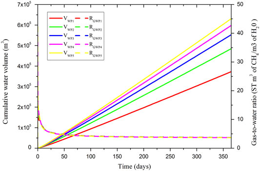
FIGURE 11. Time-varying curve of cumulative water production (VWD) and gas–water ratio (RGWD) in case of different fracture permeabilities.
Effects of Fracture Spacing on Gas Productivity
Fracture spacing can be controlled by lifting or lowering the tubing. To compare the effects of different NWAF spacing values on the productivity of hydrate deposits, the NWAF spacing was set to 1, 2, 3, 4, and 5 m, as shown in Table 4. The authors assumed that fracture depth, fracture permeability, fracture height, and the length of the completion interval were 3 m, 3 D, 0.5, and 12 m respectively.
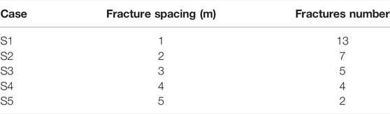
TABLE 4. Fracture spacing and corresponding calculation case.
Figures 12, 13 show the gas production rate (QTS), cumulative gas production (VTS), cumulative water production (VWS), and gas–water ratio (RGWS) at different NWAF spacing values. Figure 12 clearly demonstrates that NWAF spacing has significant effects on gas production rate (QTS). The stable gas production rate was 8,100 ST m3/day when the fracture spacing was 1 m, whereas it was only 4,300 ST m3/day when the NWAF spacing increased to 5 m. These findings show that the gas production rate increases with a decrease in the NWAF spacing. However, VTS increased by 53.3% when fracture spacing decreased from 4 to 3 m, and by 16.1% when fracture spacing decreased from 3 to 2 m. This means that the decrease in fracture spacing corresponds with the decrease in the magnitude of gas production efficiency. Therefore, a fracture spacing of 3 m is recommended for the low-permeability hydrate reservoirs at site SH7. NWAF spacing has no effect on the gas–water ratio.
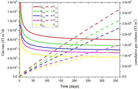
FIGURE 12. Time-varying gas production rate (QTS) and cumulative gas production (VTS) in case of different fracture spacings.
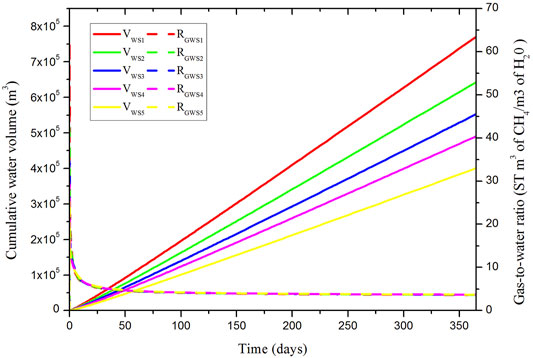
FIGURE 13. Time-varying cumulative water production (VWS) and gas–water ratio (RGWS) in case of different fracture spacings.
Discussion of the Effects of Key Parameters of NWAF on Gas Productivity
This study’s investigation of the effects of the key parameters of NWAFs, such as depth, permeability, and spacing on gas productivity during 1 year of simulated mining led to important findings. As the fracture depth increases from 1 to 5 m, cumulative gas production can increase from 154 × 104 to 273 × 104 ST m3. As the fracture permeability increases from 1 D to 5 D, the cumulative gas production can increase from 157 × 104 to 262 × 104 ST m3. As fracture spacing increases from 1 to 5 m, cumulative gas production can decrease from 318 × 104 to 126 × 104 ST m3. Gas production efficiency can be significantly increased by increasing fracture depth and permeability or by reducing fracture spacing. As mentioned previously, however, marine NGH deposits often involve unconsolidated sediments that exhibit limited shear strength, especially when the hydrates are dissociated. Under these conditions, the fractures can reduce the structural stability of NGH sediments. Therefore, when using NWAFs to increase gas production, the shear strength and structural stability of NGH sediments need to be considered in the determination of fracture depth and spacing, which will be researched by the authors in the future. After fracture depth and spacing are determined, fracture permeability, which hardly affects the structural stability of HBS, should be increased as much as possible. By comparing growth gaps between gradients under variable control, the recommended NWAF depth, permeability, and spacing are 3 m, 3 D, and 3 m, respectively for the clayey silt reservoirs at site SH7, and more detailed discussions will be investigated in a later study.
Conclusion
Low permeability significantly restricts the efficiency of gas and water flow into production wells. To enhance the gas production efficiency from low-permeability hydrate reservoirs, the high-pressure rotating water jets (HPRWJ) technology is proposed to construct near wellbore artificial fractures (NWAFs) in hydrate reservoirs. The HPRWJ can avoid the risks of hydraulic fracturing as well as large-scale reservoir damage. It is more suitable for constructing fractures in hydrate-bearing sediments (HBS). Taking site SH7 in the South China Sea as a case study, this work used numerical simulations to evaluate the feasibility of this technology for enhancing gas production of low-permeability hydrate reservoirs. The following conclusions were obtained.
(1) NWAFs constructed by the HPRWJ technology can effectively increase the gas and water production efficiency of low-permeability hydrate reservoirs. The gas productivity can be increased by about three times by constructing fractures with a depth, spacing, and height of 3 m, 3, and 0.5 m respectively based on low-permeability hydrate reservoirs at site SH7. This is mainly because high-conductivity fractures are formed near the production well, which provide rapid flow channels for gas and water, thus contributing to pressure propagation.
(2) The water in permeable boundaries can flow into production wells after a certain period of production, thereby restricting the pressure drop from being transferred into deep reservoirs and limiting hydrate dissociation to some extent. Therefore, well spacing should be properly controlled when vertical wells are employed to exploit hydrate deposits at site SH7 in the South China Sea to improve the recovery of the entire hydrate reservoir.
(3) Fracture depth, fracture permeability, and fracture spacing have significant effects on the gas productivity of hydrate reservoirs. Production efficiency increases as fracture depth, and permeability increase, and as fracture spacing decreases. However, these fracture parameters can hardly affect the gas–water ratio.
The proposed HPRWJ technology may be an efficient stimulation method for gas recovery from low-permeability hydrate reservoirs in the foreseeable future. Therefore, there is an urgent need for conducting laboratory and numerical studies related to the high-pressure rotating water jet technology and the geomechanical responses associated with fractures in the future.
Data Availability Statement
The original contributions presented in this study are included in the article/Supplementary Material, further inquiries can be directed to the corresponding authors.
Author Contributions
ZL: modeling and writing. TW: communication and guidance. YY: translation and suggestion. QL: guidance. HL: suggestion and verification. JW: suggestion and verification. LT: guidance. HH: translation. KL: suggestion. HQ: communication and guidance. All authors contributed to the article and approved the submitted version.
Funding
This paper was supported by Key Special Project for Introduced Talents Team of Southern Marine Science and Engineering Guangdong Laboratory (Guangzhou) (No. GML2019ZD0506), MNR Key Laboratory of Marine Mineral Resources Fund (KLMMR-2018-A-05), Guangdong MEPP Fund [GDOE (2019) A39], Key Special Project for Introduced Talents Team of Southern Marine Science and Engineering Guangdong Laboratory (Guangzhou) (No. GML2019ZD0307) and Guangdong Major project of Basic and Applied Basic Research (No. 2020B0301030003).
Conflict of Interest
Authors ZL, TW, YY, QL, HL, JW, LT, HH, KL, and HQ were employed by the Guangzhou Marine Geological Survey.
Publisher’s Note
All claims expressed in this article are solely those of the authors and do not necessarily represent those of their affiliated organizations, or those of the publisher, the editors, and the reviewers. Any product that may be evaluated in this article, or claim that may be made by its manufacturer, is not guaranteed or endorsed by the publisher.
Acknowledgments
The authors would like to extend their sincere appreciation to Kewei Zhang from the Guangzhou Marine Geological Survey for editing this paper.
References
Anderson, B. J., Kurihara, M., White, M. D., Moridis, G. J., Wilson, S. J., Pooladi-Darvish, M., et al. (2011). Regional Long-Term Production Modeling from a Single Well Test, Mount elbert Gas Hydrate Stratigraphic Test Well, Alaska north Slope. Mar. Pet. Geology. 28, 493–501. doi:10.1016/j.marpetgeo.2010.01.015
Aydin, G., Jang, H., and Topal, E. (2016). Energy Consumption Modeling Using Artificial Neural Networks: The Case of the World's Highest Consumers. Energ. Sourc. B: Econ. Plann. Pol. 11, 212–219. doi:10.1080/15567249.2015.1075086
Boswell, R., and Collett, T. S. (2011). Current Perspectives on Gas Hydrate Resources. Energy Environ. Sci. 4, 1206–1215. doi:10.1039/c0ee00203h
Burland, J. B. (1990). On the Compressibility and Shear Strength of Natural Clays. Géotechnique 40, 329–378. FEng. doi:10.1680/geot.1990.40.3.329
Chen, C., Yang, L., Jia, R., Sun, Y., Guo, W., Chen, Y., et al. (2017). Simulation Study on the Effect of Fracturing Technology on the Production Efficiency of Natural Gas Hydrate. Energies 10, 1241. doi:10.3390/en10081241
Chong, Z. R., Pujar, G. A., Yang, M., and Linga, P. (2016). Methane Hydrate Formation in Excess Water Simulating marine Locations and the Impact of thermal Stimulation on Energy Recovery. Appl. Energ. 177, 409–421. doi:10.1016/j.apenergy.2016.05.077
Feng, Y., Chen, L., Suzuki, A., Kogawa, T., Okajima, J., Komiya, A., et al. (2019b). Enhancement of Gas Production from Methane Hydrate Reservoirs by the Combination of Hydraulic Fracturing and Depressurization Method. Energ. Convers. Manag. 184, 194–204. doi:10.1016/j.enconman.2019.01.050
Feng, Y., Chen, L., Suzuki, A., Kogawa, T., Okajima, J., Komiya, A., et al. (2019a). Numerical Analysis of Gas Production from Layered Methane Hydrate Reservoirs by Depressurization. Energy 166, 1106–1119. doi:10.1016/j.energy.2018.10.184
Fujii, T., Noguchi, S., Takayama, T., Suzuki, T., Yamamoto, K., and Saeki, T. (2013). “Site Selection and Formation Evaluation at the 1st Offshore Methane Hydrate Production Test Site in the Eastern Nankai Trough, Japan,” in Proceedings of the 75th EAGE Conference & Exhibition-Workshops (London, UK. doi:10.3997/2214-4609.20131159
Fujii, T., Suzuki, K., Takayama, T., Tamaki, M., Komatsu, Y., Konno, Y., et al. (2015). Geological Setting and Characterization of a Methane Hydrate Reservoir Distributed at the First Offshore Production Test Site on the Daini-Atsumi Knoll in the Eastern Nankai Trough, Japan. Mar. Pet. Geology. 66, 310–322. doi:10.1016/j.marpetgeo.2015.02.037
Goto, S., Matsubayashi, O., and Nagakubo, S. (2016). Simulation of Gas Hydrate Dissociation Caused by Repeated Tectonic Uplift Events. J. Geophys. Res. Solid Earth 121, 3200–3219. doi:10.1002/2015JB012711
Hancock, S. H., Carle, D., Weatheroll, B., Dallimore, S. R., Collett, T. S., Satoh, T., et al. (2005). Overview of pressure –drawdown production-test results for the JAPEX/JNOC/GSC et al. Mallik 5L-38 gas hydrate production research well. Canada: N. P. Web.
Huang, L., Su, Z., and Wu, N.-Y. (2015). Evaluation on the Gas Production Potential of Different Lithological Hydrate Accumulations in marine Environment. Energy 91, 782–798. doi:10.1016/j.energy.2015.08.092
International Energy Outlook, Boswell, R., and Collett, T. S. (2011). Current Perspectives on Gas Hydrate Resources. Energ. Environ. Sci. 4 (4), 1206–1215. doi:10.1039/c0ee00203h
Kim, A. R., Cho, G. C., Lee, J. Y., and Kim, S. J. (2016). “May). Numerical Simulation on Geomechanical Stability during Gas Hydrate Production by Depressurization,” in 11th International Symposium on Cold Regions Development (ISCORD) (Incheon, Korea: International Association for Cold Region Development Studies (IACORDS).
Koh, D.-Y., Kang, H., Lee, J.-W., Park, Y., Kim, S.-J., Lee, J., et al. (2016). Energy-efficient Natural Gas Hydrate Production Using Gas Exchange. Appl. Energ. 162, 114–130. doi:10.1016/j.apenergy.2015.10.082
Konno, Y., Jin, Y., Shinjou, K., and Nagao, J. (2014). Experimental Evaluation of the Gas Recovery Factor of Methane Hydrate in sandy Sediment. RSC Adv. 4, 51666–51675. doi:10.1039/c4ra08822k
Konno, Y., Jin, Y., Yoneda, J., Uchiumi, T., Shinjou, K., and Nagao, J. (2016). Hydraulic Fracturing in Methane-Hydrate-Bearing Sand. RSC Adv. 6, 73148–73155. doi:10.1039/C6RA15520K
Lei, H., Yang, Z., Xia, Y., and Yuan, Y. (2022). Prospects of Gas Production from the Vertically Heterogeneous Hydrate Reservoirs through Depressurization in the Mallik Site of Canada. Energ. Rep. 8, 2273–2287. doi:10.1016/j.egyr.2022.01.170
Li, G., Huang, Z., Zhang, D., Ma, J., Shen, Z., and Niu, J. (2002). Study of Treatment of Near Well-Bore Formation Processed with High Pressure Rotating Water Jets. Pet. Sci. Tech. 20, 961–972. doi:10.1081/LFT-120003689
Li, G., Li, X.-S., Zhang, K., Li, B., and Zhang, Y. (2013). Effects of Impermeable Boundaries on Gas Production from Hydrate Accumulations in the Shenhu Area of the south China Sea. Energies 6, 4078–4096. doi:10.3390/en6084078
Li, G., Li, X. S., and Zhang, K. (2011b). Numerical Simulation of Gas Production from Hydrate Accumulations Using a Single Horizontal Well in Shenhu Area, South China Sea. Chin. J. Geophys. 54, 2325–2337. doi:10.3969/j.issn.0001-5733.2011.09.016
Li, G., Moridis, G. J., Zhang, K., and Li, X.-s. (2011a). The Use of Huff and Puff Method in a Single Horizontal Well in Gas Production from marine Gas Hydrate Deposits in the Shenhu Area of South China Sea. J. Pet. Sci. Eng. 77, 49–68. doi:10.1016/j.petrol.2011.02.009
Li, J.-f., Ye, J. L., Ye, J.-l., Qin, X.-w., Qiu, H.-j., Wu, N.-y., et al. (2018). The First Offshore Natural Gas Hydrate Production Test in South China Sea. China Geology. 1, 5–16. doi:10.31035/cg2018003
Liang, J., Wang, H., Su, X., Wang, L., Guo, Y., Chen, F., et al. (2014). Natural Gas Hydrate Formation Conditions and the Associated Controlling Factors in the Northern Slope of the South China Sea. Nat. Gas Ind. 34, 128–135. doi:10.3787/j.issn.1000-0976.2014.07.022
Liu, C. Z., Pu, W. F., Zhou, F. Y., and Yu, Q. L. (2012). The Influence of Different Artificial Cracks on Permeability by experiment. Spec. Oil Gas Reserve 19, 117–121. doi:10.3969/j.issn.1006-6535.2012.04.030
Ma, X., Sun, Y., Guo, W., Jia, R., Li, B., Yuang, Y., et al. (2021). Numerical Simulation of Horizontal Well Hydraulic Fracturing Technology for Gas Production from Hydrate Reservoir. Appl. Ocean Res. 112, 102674. in press. doi:10.1016/j.apor.2021.102674
Makogon, Y. F., and Omelchenko, R. Y. (2013). Commercial Gas Production from Messoyakha deposit in Hydrate Conditions. J. Nat. Gas Sci. Eng. 11, 1–6. doi:10.1016/j.jngse.2012.08.002
Moridis, G. J., Kim, S-J., and Seol, Y. (2007b). “Evaluation of the Gas Production Potential of Oceanic Hydrate Deposits in the Ulleung Basin of the Korean East Sea,” in Asia Pacific Oil and Gas Conference and Exhibition (Jakarta, Indonesia: OnePetro). doi:10.2118/110859-ms
Moridis, G. J., Kowalsky, M. B., and Pruess, K. (2008). TOUGH + HYDRATE V1.0 User's Manual: A Code for the Simulation of System Behavior in Hydrate-Bearing Geologic Media.
Moridis, G. J., and Kowalsky, M. B. (2007a). Response of Oceanic Hydrate-Bearing Sediments to thermal Stresses. SPE J. 12, 253–268. doi:10.2118/111572-pa
Moridis, G. J., and Reagan, M. T. (2011). Estimating the Upper Limit of Gas Production from Class 2 Hydrate Accumulations in the Permafrost: 2. Alternative Well Designs and Sensitivity Analysis. J. Pet. Sci. Eng. 76, 124–137. doi:10.1016/j.petrol.2010.12.001
Moridis, G. J., and Sloan, E. D. (2007c). Gas Production Potential of Disperse Low-Saturation Hydrate Accumulations in Oceanic Sediments. Energ. Convers. Manag. 48, 1834–1849. doi:10.1016/j.enconman.2007.01.023
Moridis, G. J. (2014). User’s Manual for the Hydrate v1.5 Option of TOUGH+ v1.5: A Code for the Simulation of System Behavior in Hydrate-Bearing Geologic Media.
Mu, L., and von Solms, N. (2020). Inhibition of Natural Gas Hydrate in the System Containing Salts and Crude Oil. J. Pet. Sci. Eng. 188, 106940. doi:10.1016/j.petrol.2020.106940
Myshakin, E. M., Seol, Y., Lin, J. S., Uchida, S., Collett, T. S., and Boswell, R. (2018). Numerical Simulations of Depressurization-Induced Gas Production from an Interbedded Turbidite Gas Hydrate-Bearing Sedimentary Section in the Offshore India: Site NGHP-02-16 (Area-B). Mar. Petrol. Geol. 108, 619–638. doi:10.1016/j.marpetgeo.2018.10.047
Qorbani, K., Kvamme, B., and Kuznetsova, T. (2017). Using a Reactive Transport Simulator to Simulate CH4 Production from Bear Island Basin in the Barents Sea Utilizing the Depressurization Method†. Energies 10, 187. doi:10.3390/en10020187
Rossi, F., Gambelli, A. M., Sharma, D. K., Castellani, B., Nicolini, A., and Castaldi, M. J. (2018). Experiments on Methane Hydrates Formation in Seabed Deposits and Gas Recovery Adopting Carbon Dioxide Replacement Strategies. Appl. Therm. Eng. 148, 371–381. doi:10.1016/j.applthermaleng.2018.11.053
Sloan, E. D., Koh, C. A., and Koh, C. A. (2008). “Clathrate Hydrates of Natural Gases,” in Clathrate Hydrates of Natural Gases (Boca Raton, FL: CRC Press). 3re. doi:10.1201/9781420008494
Su, Z., Cao, Y. C., Yang, R., Zhang, K. N., and Wu, N. Y. (2011). Feasibility of Gas Production from Hydrate Reservoir Considering Heat Conduction: Taking Shen Hu Area in the South China Sea as an Example. Geoscience 25, 608–616. doi:10.1007/s12182-011-0118-0
Su, Z., Huang, L., Wu, N., and Yang, S. (2013). Effect of thermal Stimulation on Gas Production from Hydrate Deposits in Shenhu Area of the South China Sea. Sci. China Earth Sci. 56, 601–610. doi:10.1007/s11430-013-4587-4
Su, Z., Moridis, G. J., Zhang, K., and Wu, N. (2012). A Huff-And-Puff Production of Gas Hydrate Deposits in Shenhu Area of South China Sea through a Vertical Well. J. Pet. Sci. Eng. 86-87, 54–61. doi:10.1016/j.petrol.2012.03.020
Su, Z., Moridis, G., Zhang, K., Yang, R., and Wu, N. (2010). “Numerical Investigation of Gas Production Strategy for the Hydrate Deposits in the Shenhu Area, OTC 20551,” in Proceedings of the Offshore Technology Conference (Houston, Texas, USA.
Sun, X., Luo, H., Luo, T., Song, Y., and Li, Y. (2019a). Numerical Study of Gas Production from marine Hydrate Formations Considering Soil Compression and Hydrate Dissociation Due to Depressurization. Mar. Pet. Geology. 102, 759–774. doi:10.1016/j.marpetgeo.2019.01.035
Sun, Y.-h., Jia, R., Guo, W., Zhang, Y.-q., Zhu, Y.-h., Li, B., et al. (2012). Design and Experimental Study of the Steam Mining System for Natural Gas Hydrates. Energy Fuels 26, 7280–7287. doi:10.1021/ef3014019
Sun, Y., Zhong, J., Chen, G., and Sun, C. (2019b). Enhanced Depressurization for Methane Recovery from Hydrate-Bearing Sediments by Ethylene Glycol Pre-injection. Energ. Proced. 158, 5207–5212. doi:10.1016/j.egypro.2019.01.674
The Ignik Sikumi gas hydrate exchange trial project team (2012). Ignik Sikumi Gas Hydrate Field Trial Completed. Fire in the Ice 12, 1–24.
Too, J. L., Cheng, A., Khoo, B. C., Palmer, A., and Linga, P. (2018a). Hydraulic Fracturing in a Penny-Shaped Crack. Part II: Testing the Frackability of Methane Hydrate-Bearing Sand. J. Nat. Gas Sci. Eng. 52, 619–628. doi:10.1016/j.jngse.2018.01.046
Too, J. L., Cheng, A., and Linga, P. (2018b). “Fracturing Methane Hydrate in Sand: a Review of the Current Status,” in Proceedings of the Offshore Technology Conference Asia (Malaysia: Kuala Lumpur). doi:10.4043/28292-ms
Wang, X., Hutchinson, D. R., Wu, S., Yang, S., and Guo, Y. (2011). Elevated Gas Hydrate Saturation within silt and Silty clay Sediments in the Shenhu Area, South China Sea. J. Geophys. Res. Solid Earth 116, B05102. doi:10.1029/2010JB007944
Wang, Y., Li, X.-S., Li, G., Zhang, Y., Li, B., and Feng, J.-C. (2013). A Three-Dimensional Study on Methane Hydrate Decomposition with Different Methods Using Five-Spot Well. Appl. Energ. 112, 83–92. doi:10.1016/j.apenergy.2013.05.079
Wei, J., Yang, L., Liang, Q., Liang, J., Lu, J., Zhang, w., et al. (2021). Geomechanical Properties of Gas Hydrate-Bearing Sediments in Shenhu Area of the South China Sea. Energy Rep. press. doi:10.1016/j.egyr.2021.05.063
Wu, N., Zhang, S., Zhang, G., Liang, J., and Lu, J. (20112011). Gas Hydrate System of Shenhu Area, Northern South China Sea: Geochemical Results. J. Geol. Res., 370298. doi:10.1155/2011/370298
Xu, Y. C., Xi, Y. T., and Lin, Y. C. (2016). The Experimental Analysis on Permeable Performance of Foamed concrete. Low Temperature Architecture Tech. 38, 8–11. doi:10.13905/j.cnki.dwjz.2016.10.004
Yamamoto, K., and Dallimore, S. (2008b). Aurora-JOGMEC-NRCan Mallik 2006-2008 Gas Hydrate Research Project Progress. Pittsburgh, PA: U.S. Department of Energy, Office of Fossil Energy. National Energy Technology Laboratory Fire In the Ice Newsletter.
Yamamoto, K., and Dallimore, S. (2008a). Aurora-JOGMEC-NRCanan Mallik 2006–2008 Gas Hydrate Research Project Progress. Fire in the Ice 8, 1–5.
Ye, J., Qin, X., Xie, W., Lu, H., Ma, B., Qiu, H., et al. (2020). Main Progress of the Second Gas Hydrate Trial Production in the South China Sea. Geology. China 47, 557–568. doi:10.12029/gc20200301
Yoneda, J., Masui, A., Konno, Y., Jin, Y., Kida, M., Katagiri, J., et al. (2017). Pressure-core-based Reservoir Characterization for Geomechanics: Insights from Gas Hydrate Drilling during 2012-2013 at the Eastern Nankai Trough. Mar. Pet. Geology. 86, 1–16. doi:10.1016/j.marpetgeo.2017.05.024
Yoneda, J., Oshima, M., Kida, M., Kato, A., Konno, Y., Jin, Y., et al. (2019). Permeability Variation and Anisotropy of Gas Hydrate-Bearing Pressure-Core Sediments Recovered from the Krishna-Godavari Basin, Offshore India. Mar. Pet. Geology. 108, 524–536. doi:10.1016/j.marpetgeo.2018.07.006
Yu, T., Guan, G., Abudula, A., Yoshida, A., Wang, D., and Song, Y. (2019). Heat-assisted Production Strategy for Oceanic Methane Hydrate Development in the Nankai Trough, Japan. J. Pet. Sci. Eng. 174, 649–662. doi:10.1016/j.petrol.2018.11.085
Yuan, Y., Xu, T., Jin, C., Zhu, H., Gong, Y., and Wang, F. (2021b). Multiphase Flow and Mechanical Behaviors Induced by Gas Production from Clayey-silt Hydrate Reservoirs Using Horizontal Well. J. Clean. Prod. 328, 129578. doi:10.1016/j.jclepro.2021.129578
Yuan, Y., Xu, T., Xin, X., Gong, Y., and Li, B. (2021a). Enhanced Gas Production from Clayey-silt Hydrate Reservoirs Based on Near-Well Reservoir Reconstruction Using the High-Pressure Jet Grouting Technology. J. Nat. Gas Sci. Eng. 94, 4121. doi:10.1016/j.jngse.2021.104121
Yuan, Y., Xu, T., Xin, X., and Xia, Y. (2017). Multiphase Flow Behavior of Layered Methane Hydrate Reservoir Induced by Gas Production. Geofluids 2017, 1–15. doi:10.1155/2017/7851031
Nomenclature
k Permeability, m2
g Gravitational acceleration vector, m/s2
b Klinkenberg factor, Pa
T Temperature, °C
λ Average thermal conductivity, W/(m·K)
β Phase, β = A,G,H,I is aqueous, gas, hydrate, and ice, respectively
κ Component, κ = w,m,i,h is water, methane, salt, and hydrate, respectively
Keywords: natural gas hydrate, high-pressure rotating water jets, near wellbore artificial fractures, low-permeability reservoirs, production enhancement
Citation: Li Z, Wan T, Yu Y, Liang Q, Lu H, Wang J, Tian L, He H, Li K and Qiu H (2022) Enhancement of Gas Production From Clayey Silt Hydrate Reservoirs Based on Near Wellbore Artificial Fractures Constructed Using High-Pressure Rotating Water Jets Technology. Front. Earth Sci. 10:870582. doi: 10.3389/feart.2022.870582
Received: 07 February 2022; Accepted: 21 March 2022;
Published: 29 April 2022.
Edited by:
Jinan Guan, Guangzhou Institute of Energy Conversion (CAS), ChinaReviewed by:
Ye Chen, China University of Petroleum, Huadong, ChinaYilong Yuan, Jilin University, China
Guangrong Jin, Guangzhou Institute of Energy Conversion (CAS), China
Copyright © 2022 Li, Wan, Yu, Liang, Lu, Wang, Tian, He, Li and Qiu. This is an open-access article distributed under the terms of the Creative Commons Attribution License (CC BY). The use, distribution or reproduction in other forums is permitted, provided the original author(s) and the copyright owner(s) are credited and that the original publication in this journal is cited, in accordance with accepted academic practice. No use, distribution or reproduction is permitted which does not comply with these terms.
*Correspondence: Tinghui Wan, ODI1ODQ4NjUxQHFxLmNvbQ==; Haijun Qiu, ODQ5MjM4NDIzQHFxLmNvbQ==