 Yan Wang
 Yafeng Tang2
 Fei Zhang
 Jinlong Guo
- 1School of Engineering, Fujian Jiangxia University, Fuzhou, China
- 2China Railway Siyuan Survey and Design Group Co., Ltd., Wuhan, China
Under the impact of seismic forces, the strain of conventional anchor cables tended to increase sharply in an instant, which could easily cause the anchor cables to fail due to stress overload. This study aimed to optimize the design of rock supporting methods under dynamic disaster events such as earthquakes and rock bursts. A scale model specimen with a mechanical sliding device was designed based on an anti-seismic anchor cable. The working mechanism and seismic strain response of anti-seismic anchor cables were studied using static and shaking table model tests. The results show that under a static force, the anti-seismic anchor cables undergo in sequence a first elastic deformation stage, a slipping stage, a second elastic deformation stage, a plastic strengthening stage, and a brittle failure stage. In the slipping stage, the anchor cables start frictional sliding while keeping the axial force unchanged so as to adapt to the large deformation of the rock mass. The anti-seismic anchor cables exhibit the three situations of no-slip, instantaneous slip, and gradual and accumulative slip under seismic excitation. With a large constant resistance to slippage, the anchor cables do not slip, which can easily cause the anchor cables to break due to stress overload. With a small constant resistance to slippage, the reserved slipping distance is instantly exhausted; a step-shaped jump appears in the time history curves of the strain of the anchor cables. In the engineering design, a preset constant resistance to slippage is needed to match the seismic force for the anchor cables to exhibit the mechanism of multiple accumulated slips. During each slipping process, the strain of the anchor cables first decreases and then increases, with the peak strain decreasing significantly. This mechanism effectively cushions the instantaneous impact force of the earthquake, releases rock deformation, and dissipates seismic energy.
1 Introduction
Southwest China’s location in an earthquake-prone zone readily exposes it to seismic activity, causing landslides, collapses, and other geological disasters within a complex geological environment. The problem of slope stability under the action of a range of adverse factors such as earthquakes, rainfall, load stacking, unloading, and excavations remains a long-standing and perennially difficult problem (Shi et al., 2015; Tang et al., 2015; Mu et al., 2020; Tiwari and Latha, 2020; Yang and Zhang, 2020). The previous investigations into the landslide and collapse disasters caused by earthquakes found that when a slope was unstable due to an earthquake, the anchor cables within the slope had sustained local damage as the seismic action had instantaneously produced enormous impact forces (Zheng et al., 2015; Fan et al., 2016; Massey et al., 2017; Bian et al., 2018; Zhang et al., 2019). The anti-seismic reinforcement capacity of the conventional anchor cables is often restricted owing to their insufficient deformation capacity. Therefore, under powerful seismic action, it is difficult for the conventional anchor cables to achieve the required reinforcement effect.
Scholars at home and abroad have developed a variety of new anchor cables after extensive research and tests, which have been proven to offer good anti-seismic performance. The typical new anti-seismic anchor cables from abroad are the Garford bolt from Australia (Sengani, 2018), Roofex bolt from Austria (Ozbay and Neugebauer, 2009), the Yield-Lok bolt (Wu and Oldsen, 2010), Cone bolt from Canada (Cai and Champaigne, 2012; Liang Y. et al., 2017), a new energy-absorbing bolt from Sweden (Krzysztof, 2018), and the D-bolt from Norway (Li, 2012; Li and Doucet, 2012). In China, there are the CRLD constant resistance and large deformation anchor cable (Tao et al., 2017; Lv et al., 2018), the NPR new constant resistance and large deformation anchor cable (He et al., 2016; He et al., 2017), a new high strength and high pretension yieldable anchor cable (Lian et al., 2010; Li et al., 2017), and an extrusion sleeve–type yield anchor cable (Zhang et al., 2015). The researchers at home and abroad have carried out numerous field static tensile tests and engineering application tests on the new type of anti-seismic anchor cables, which have verified the advantages of these innovative anti-seismic anchor cables over conventional ones, such as large deformation capacity and good resistance to static and dynamic load (Srilatha et al., 2016; He et al., 2018; Xu et al., 2018; Yang et al., 2018; Zhan et al., 2019; Nie et al., 2020).
At present, the research on slope engineering is mostly focused on the dynamic response of slopes, deformation, and failure mechanism of slopes, earthquake influence coefficient, and composite support structure (Li et al., 2016; Liang J. X. et al., 2017; Fan et al., 2017; Lin et al., 2017; Xu et al., 2017; Zhang et al., 2017). Although research on the mechanical characteristics, working mechanisms, strain response attributes, and failure modes of anti-seismic anchor cables remains relatively scarce, targeted research needs to be carried out. In addition, research on new anti-seismic anchor cables is mostly carried out using field tests and numerical simulations (Lai et al., 2016; Zhou et al., 2016; Zhu et al., 2017; Tao et al., 2020). Field testing is time-consuming, difficult to implement, and inconvenient to adjust parameters. Although numerical simulation offers the benefits of low cost and high ease of implementation, the results still need to be supported by corresponding experiments. Laboratory model tests present the advantages of good economy, strong pertinence, and accurate data (Jing et al., 2020a; Jing et al., 2020b; Jing et al., 2020c). In the present study, a prototype specimen and scale model specimen of anti-seismic anchor cables were used as the research objects. The working mechanism, seismic strain response, and seismic anchoring mechanism of anti-seismic anchor cables were studied using static and shaking table model tests. The research results were intended to provide references for the design of rock support in areas prone to high seismic activity.
2 Basic Structure of Anti-Seismic Anchor Cables
Anti-seismic anchor cables mainly comprise a bearing plate, anti-seismic anchor, permanent anchor, and steel strand. The steel strand passes in turn through the bearing plate, anti-seismic anchor, and permanent anchor, and a certain distance is preset between the permanent anchor and the anti-seismic anchor to allow for the slipping displacement of the anti-seismic anchor cable. Among these, the anti-seismic anchor is a sliding extrusion sleeve structure that can slide smoothly while providing a constant anchoring force, whereas the permanent anchor is a standard fixed extrusion sleeve structure, and hence cannot slide. The basic structure and physical photograph of the anti-seismic anchor cable are shown in Figure 1.
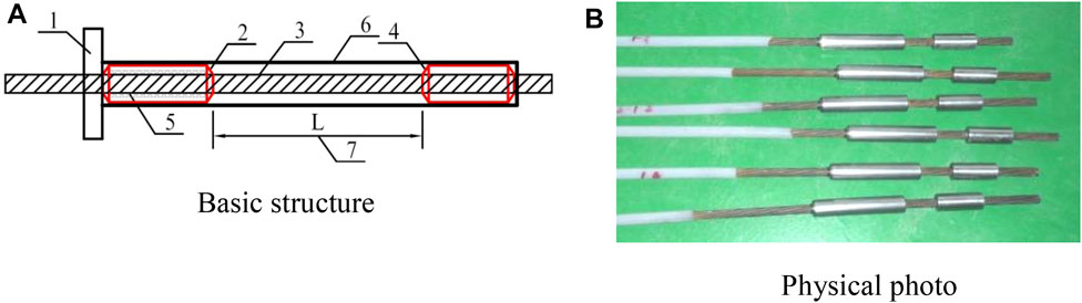
FIGURE 1. Basic structure and photograph of an anti-seismic anchor cable. 1-bearing plate; 2-anti-seismic anchor (sliding extrusion sleeve); 3-unbonded steel strand; 4-permanent anchor (fixed extrusion sleeve); 5-frictional material fill; 6- seal cover; 7-preset slipping distance. (A) Basic structure. (B) Physical photo.
When an earthquake impacts an anchored slope, the force on the anchor cable increases sharply. When the impact force exceeds the frictional force between the anti-seismic anchor and anchor cable (i.e., the preset constant resistance to slippage), stable frictional sliding occurs between the anchor cable and anti-seismic anchor, which effectively cushions the instantaneous impact force of the earthquake, thereby preventing the anchor cable body from being ripped off due to stress overload or insufficient deformation capacity. Therefore, the significant deformation of the rock mass is adapted and the ductility of the failure of the overall anchor structure is increased to achieve the purpose of seismic reinforcement.
3 Mechanical Properties of Anti-Seismic Anchor Cables
3.1 Tensile Test of Anti-Seismic Anchor Cables
The mechanical properties test of the anti-seismic anchor cable used the prototype sample. Three groups of single-beam and same type anti-seismic anchor cables were selected to undergo a tensile test by the uniform loading method. The schematic diagram of the tensile test is shown in Figure 2. During the tests, the displacement positions of the anti-seismic anchors were observed, and the stop signal for each test was the point when the anti-seismic anchor was no longer generating slip. This enabled the slip control load of a single-beam anti-seismic anchor cable to be obtained. Once the slipping of the anti-seismic anchor cable had ceased, tensile failure testing of the abovementioned specimens was continued to establish the force characteristics of the anti-seismic anchor cable after slipping. The load-displacement curve under static load is shown in Figure 3. It can be seen that the stable load value of slipping of the anti-seismic anchor cable was generally around 200 kN, the average value of the corresponding sliding displacement was 37 mm, and the average value of the maximum tension was 260 kN. The constant resistance to slippage was designed to equate 80% of the yield strength of the anchor cable.
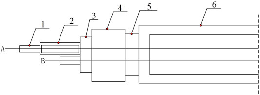
FIGURE 2. Schematic diagram of tensile test; 1-anti-seismic anchor; 2-cushion block; 3-tool anchor; 4-force sensor; 5-limit plate; 6-tension table.
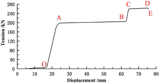
FIGURE 3. Load-displacement curve under static load.
In order to verify the force characteristics of anti-seismic anchor cables under dynamic repeated load, three groups of single-beam, same type anti-seismic anchor cables were selected for repeated loading and unloading tests. The test results are shown in Figure 4. The test results showed that in the repeated loading and unloading process, the control loads of slipping of the anti-seismic anchor cable were 200 kN (1st time), 211 kN (2nd time), 213 kN (3rd time), 215 kN (4th time), and 216 kN (5th time), and the maximum increase was 8%. The variations were not readily discernible. When the applied load once again equated the control load of slip, the anti-seismic anchor slipped, and the displacement began to increase further. This showed that the anti-seismic anchor cable was not sensitive to dynamic variable loading and that its anchoring effect had not weakened. In contrast to the conventional anchor cables where the boundary anchoring force would weaken under dynamic loading, the anti-seismic anchor cable slipped step-by-step under dynamic loading, which had the capacity to reduce the impact on the end-anchoring force by cyclic loading and unloading.
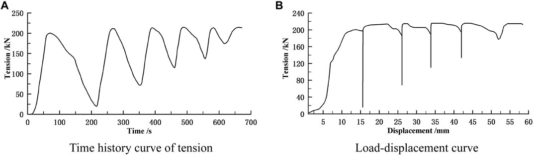
FIGURE 4. Test results under loading/unloading condition. (A) Time history curve of tension. (B) Load-displacement curve.
3.2 Working Mechanisms of Anti-Seismic Anchor Cables
The most important characteristics of anti-seismic anchor cables are their capacity to compensate for the lack of plastic deformation of their structural materials to meet the requirements for large deformation of the slope. The working mechanisms of anti-seismic anchor cables were established based on the results of the static tensile tests, as shown in Figure 5. Point A corresponds to the initial slip of the anchor cable, and the corresponding axial force of the anchor cable is Frs; point B marks the end of the slip and the initiation of the second elastic deformation stage, where the corresponding axial force of the anchor cable is Fre; point C indicates that the second elastic deformation of the anchor cable has ended and the start of the plastic strengthening stage, where the corresponding axial force of the anchor cable is Fs; point D is the end of the plastic strengthening stage of the anchor cable material and the point where the failure stage is about to be entered, where the corresponding axial force of the anchor cable is Fpe; point E represents the breaking point of the anchor cable, where the corresponding axial force of the anchor cable is Fp.
1) The OA stage is the first elastic deformation stage: the anchor cable was anchored to the slope rock mass, the initial stress on the anchor cable was small, and the axial force of the anchor cable gradually increased with the generation, propagation, and penetration of the slope crack.
2) The AB stage is the slipping stage: the continuous deformation of the rock mass caused the axial force of the anchor cable to increase continuously. When the constant resistance to slippage was exceeded, frictional sliding of the anchor cable body started, while the axial force was kept unchanged. At this stage, the working mechanism of the anti-seismic anchor cable consisted in adjusting uneven stress, energy absorption, and energy consumption.
3) The BC stage is the second elastic deformation stage: when the anchor cable reached the preset maximum slipping displacement ∆AB, the slip ended, and the free section of the anchor cable was no longer elongating. At that point, the force characteristics of the anti-seismic anchor cable equated that of a conventional pressure-type anchor cable, and the stress state returned to the elastic stage.
4) The CD stage is the plastic strengthening stage of the material: when the axial force of the anchor cable reached the yield limit Fs, plastic deformation began to develop.
5) The DE stage is the brittle failure stage of the material: when the anchor cable reached the ultimate stress Fpe and the ultimate strain of materials, the anchor cable broke.
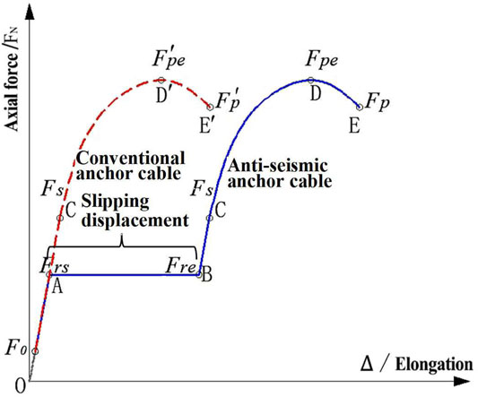
FIGURE 5. Axial force-elongation curve of conventional and anti-seismic anchor cables.
4 Shaking Table Model Test
4.1 Model Similarity Design
In the similarity design of the model test, the geometric size, acceleration, and density were taken as the basic quantities for the similarity design. The similarity ratio of geometric size was 100:1, the acceleration was 1:1, and the density was 1:1. The similarity constants of other parameters were derived from the basic quantities using the dimensional analysis method. Since the main research object of this work was the strain response of the anti-seismic anchor cables, the elastic modulus of the slope was related to the deformation of the slope, and it did not need to guarantee its strict similarity. Last, the similarity constants of each physical quantity were obtained, as shown in Table 1.
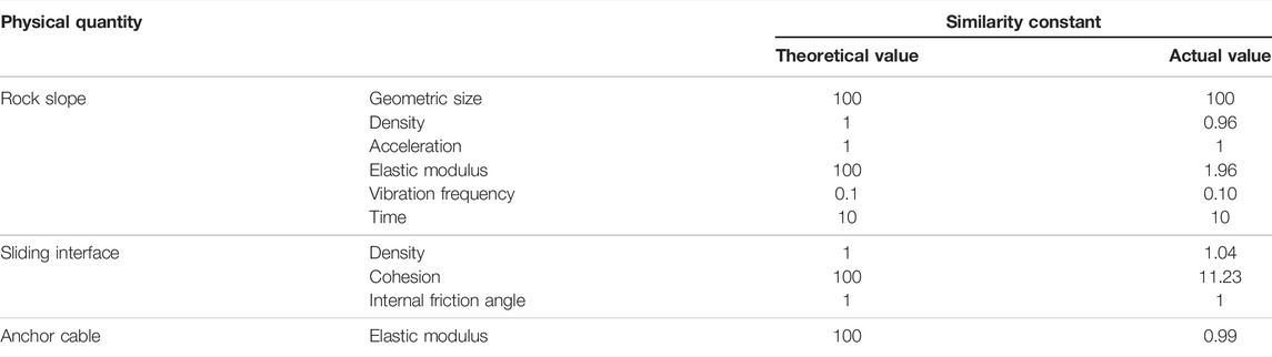
TABLE 1. Similarity constants of the shaking table model.
4.2 Anchor Cable Specimen
4.2.1 Design of the Anchor Cable Specimen
In order to study the strain response characteristics of the anti-seismic anchor cables, a scale model specimen was designed based on the mechanical characteristics and friction energy dissipation mechanism of anti-seismic anchor cables. The anchor cable specimen included the following: a steel strip (simulating steel strand), fixed nut (simulating permanent anchor), and wooden splint (simulating anti-seismic anchor). The frictional resistance between the wooden splint and steel strip was compared with the constant resistance to slippage of the anti-seismic anchor, and the reserved distance between the fixed nut and wooden splint was compared with the slipping displacement of the anti-seismic anchor cable. The width, thickness, and cross-sectional area of the steel strip were 11 mm, 0.6 mm, and 6.6 mm2, respectively. According to the material properties test, the elastic modulus, tensile strength, and axial stiffness of the anchor cable specimen were 212 GPa, 1,200 MPa, and 1,399.2 kN, respectively. Three strain measuring points were arranged along the longitudinal direction of the anchor cable specimen. The anchor cable specimen is shown in Figure 6.
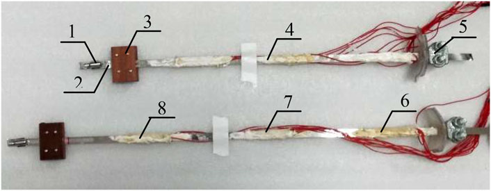
FIGURE 6. Anchor cable specimen. 1-fixed nut; 2-preset slipping distance; 3-wooden splint; 4-steel strip; 5-steel clamps; 6–1st strain measuring point; 7–2nd strain measuring point; and 8–3rd strain measuring point.
4.2.2 Static Tensile Test of Anchor Cable Specimens
The static tensile tests of three anchor cable specimens were carried out using the universal static material testing machine. Before slipping, the anchor cable was loaded at a uniform speed of 20 mm/min, and after slipping, it was loaded at a uniform speed of 50 mm/min. The time history curves of the strain of anchor cable specimens are shown in Figure 7, where Figure 7B is an enlarged partial view of Figure 7A. It can be seen that in the AB stage, the axial force of the anchor cable specimens approximately correlated positively with the elongation (corresponding to the OA stage in chapter 3 abovementioned, which is similar as follows); in the BC stage, the elongation of anchor cable specimens increased steadily under the condition that the axial force was kept constant (AB stage); in the CD stage, the anchor cable specimens showed obvious elastic stress characteristics (BC stage); in the DE stage, the axial force of anchor cable specimens increased sharply under less elongation (CD stage); in the EF stage, the elongation of anchor cable specimens increased sharply until destruction under the condition of an essentially constant axial force (DE stage). The test results showed that in the static tensile test, each stress stage of anchor cable specimens was fundamentally consistent with the mechanical properties of the anti-seismic anchor cables described in Chapter 3 previously.
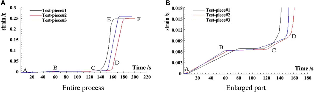
FIGURE 7. Time history curves of strain of anchor cable specimens. (A) Entire process. (B) Enlarged part.
4.3 Slope Model Design
The experimental model of the anchored slope is shown in Figure 8. The slope body was poured with C20 concrete and the measured density and the elastic modulus of the slope model were 2,570 kg/m3 and 20.5 GPa, respectively. For the simulation of the sliding interface of the slope, the slope model No. 1 used a mixture of clay and fine sand, and slope model No. 2 used a mixture of clay and gypsum; the measured density, cohesion, and internal friction angle of this mixture were 1,960 kg/m3, 15.2 kPa, and 25.8°, respectively. The arrangement of the anchor cable specimens is shown in Figure 8B.
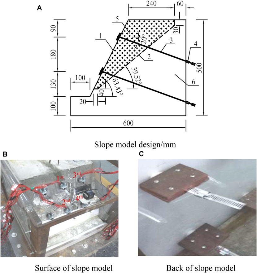
FIGURE 8. Experimental model of the anchored slope. 1-slope surface; 2-sliding interface; 3-anchor cable; 4-anti-seismic anchor; 5-sliding block; 6-bedrock. (A) Slope model design/mm. (B)Surface of slope model. (C) Back of slope model.
An experimental system was adopted in the form of a small earthquake simulation shaking table, which had the capacity to be loaded simultaneously both horizontally and vertically. Before the start of the test, the slope model was excited with bidirectional white noise sweep loading. The acceleration amplitude of the white noise was 0.05 g. Through the spectrum analysis method, the amplitude–frequency characteristic curve of the slope model was obtained. The natural vibration frequency was 10.7 Hz, and the damping ratio was 0.0587.
4.4 Loading Scheme Design
In the shaking table test, the sinusoidal wave, Tianjin wave, EI wave, and Taft wave after correction and filtering using the fundamental wave were used. The excitation method was concurrent horizontal and vertical loading. The vertical amplitude of the seismic acceleration was 2/3 of the horizontal amplitude. The time compression ratio was 10. The detailed loading scheme of model tests is shown in Table 2.
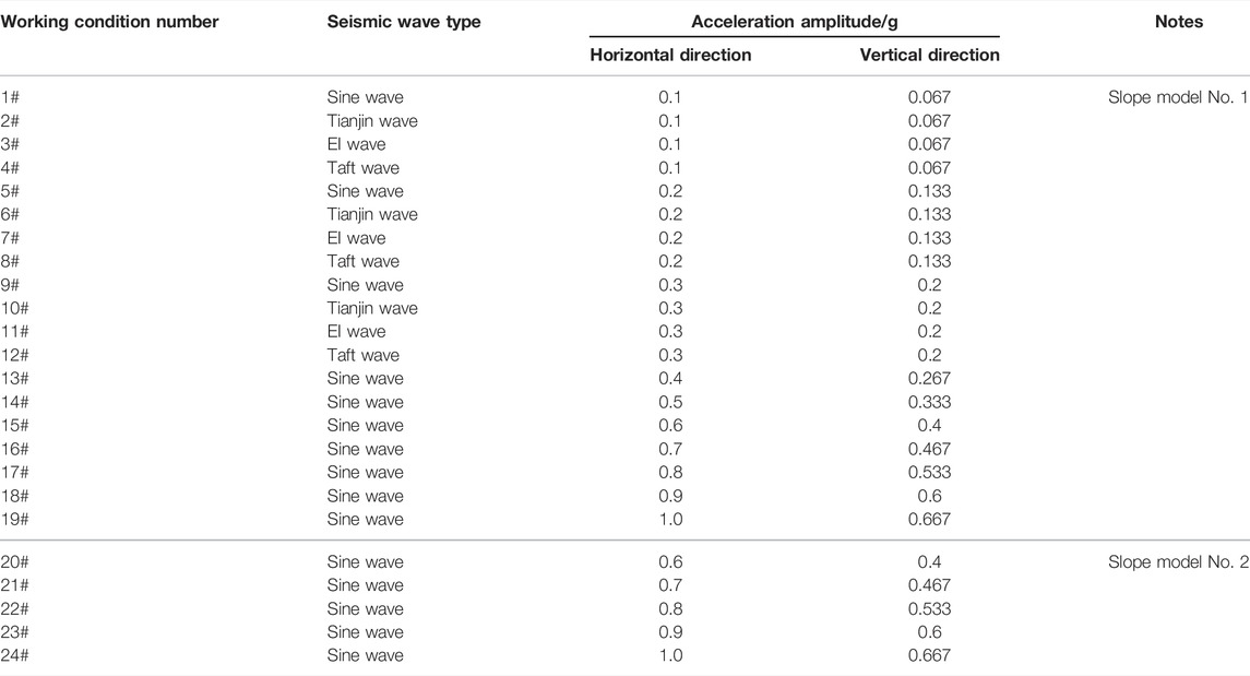
TABLE 2. Loading scheme of model tests.
5 Test Results and Discussion
5.1 No-Slip Situation of Anti-Seismic Anchor Cables
Under working condition Nos. 14–19, it can be seen that the anti-seismic anchor cable specimen did not slip, and its strain fluctuated smoothly. The anchored slope maintained good stability. The time history curves of the strain of the anti-seismic anchor cable specimens are shown in Figure 9. The data in the figure are the test results of the 1st measuring point of the 1st anchor cable specimen. In this instance, the anti-seismic anchor cable had a similar force mechanism to that of the conventional pressure-type anchor cable. The peak strain of the anti-seismic anchor cable continued to increase with the increase in seismic acceleration amplitude, and the maximum peak strain was 119.7 × 10⁻⁶, as shown in Table 3. Under these working conditions, the anchor cables were sensitive to the instant impact of the earthquake. Once subjected to strong seismic forces, the axial force of the anchor cable increased sharply, which inevitably caused a surge in the risk of failure of the anchor cable due to stress overload, thus seriously endangering the safety of the entire anchored slope.
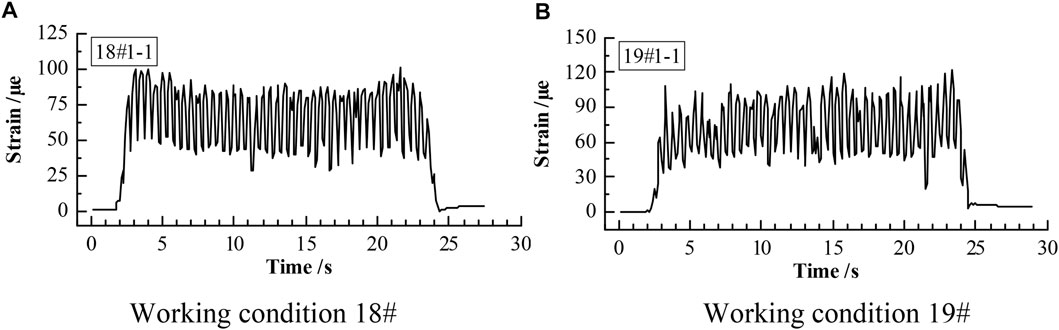
FIGURE 9. Time history curves of strain of anti-seismic anchor cables in no-slip situation. (A) Working condition 18#. (B) Working condition 19#.
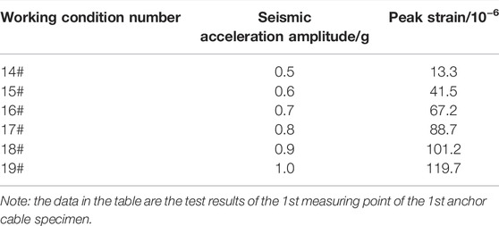
TABLE 3. Peak strain of anti-seismic anchor cables in no-slip situation.
5.2 Instantaneous Slip Situation of Anti-Seismic Anchor Cables
Under working condition Nos. 22–24, it can be seen that the anti-seismic anchor cable specimen had slipped, and its strain increased rapidly after the end of the slipping. The time history curves of strain of the anti-seismic anchor cable specimens are shown in Figure 10. The data in the figure are the test results of the 1st–3rd measuring points of the 1st anchor cable specimen. In this instance, the strain time history curves displayed a step-shaped jump, and the reserved slipping distance was instantly exhausted during the vibration process. When the seismic acceleration amplitudes were 0.8, 0.9, and 1.0 g, the increase ratios of the peak strain of the anchor cable before and after slip were 81, 79, and 74%, respectively, and the corresponding slipping start times were 10.33, 9.85, and 7.35 s, respectively, as shown in Table 4. As the amplitude of seismic acceleration increased, the peak strain of the anchor cable increased gradually, and the slipping start time was brought forward gradually. Under strong seismic conditions, the anti-seismic anchor cable slipped instantly because the preset constant resistance to slippage was too small, and the mechanism of frictional slip could not provide energy consumption.
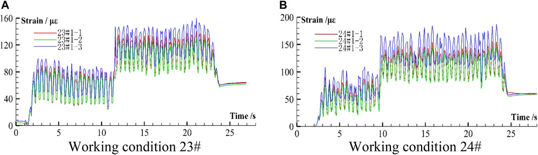
FIGURE 10. Time history curves of strain of anti-seismic anchor cables in instantaneous slip situation. (A) Working condition 23#. (B) Working condition 24#.
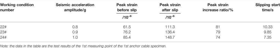
TABLE 4. Peak strain of the anti-seismic anchor cables in instantaneous slip situation.
5.3 Gradual and Accumulative Slip Situation of Anti-Seismic Anchor Cables
Under working conditions No. 20, the time history curves of the strain of the anti-seismic anchor cable specimens are shown in Figure 11. The data in the figure are the test results of the 1st–3rd measuring points of the 1st anchor cable specimen. It can be seen that the anchor cable slipped gradually and in stages, and its peak strain value was significantly lower than that in non-slip and instantaneous slip situations. The preset constant resistance to slippage of the anti-seismic anchor cable matched the seismic force under this working condition. The time history curve of the strain of the anti-seismic anchor cables was roughly divided into five stages: OA stage was the static strain before the earthquake. AB stage was the initial stage of seismic loading, where the slope model began to vibrate, and the strain of anchor cable specimens increased sharply because of the impact force. The stages of BC, CD, and DE corresponded to three slipping processes of the anti-seismic anchor cable. In each slipping process, the change trend of the anchor cable strain was first decreasing and then increasing. When the anchor cable began to slide, the force of the anchor cable was reduced due to the temporary reduction of the restraint on the sliding body. When the slip ceased, the force of the anchor cable increased because that provided supporting force again. When the axial force of the anchor cable exceeded the constant resistance to slippage, the anchor cable started to slip again. The reserved slipping distance of the anti-seismic anchor cable was exhausted by multiple accumulations. The displacement of a single slip was correlated with the curvature of the time history curve of strain and the time of strain recovery. The EF stage was the termination of seismic dynamic response; the stress of the anchor cable tended toward a certain value that was in a static state.
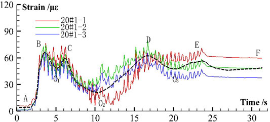
FIGURE 11. Time history curves of strain of anti-seismic anchor cables in gradual and accumulative slip situation.
5.4 Discussion
According to the test results, the strain response of the anti-seismic anchor cables varied with the loading intensity of the ground motion, and three different situations were observed: 1) When the seismic force was small and the constant resistance to slippage was large, the sliding body did not slip; 2) When the seismic force was large and the constant resistance to slippage was small, the anti-seismic anchor cables slipped instantly, and the reserved sliding distance was exhausted all at once; 3) When the seismic force and the constant resistance to slippage were set to appropriate values, the anti-seismic anchor cables slipped gradually, and the reserved sliding distance was exhausted through multiple accumulation.
Therefore, in the engineering design of the anti-seismic anchor cables, the preset constant resistance to slippage should match the seismic inertial force of the sliding body. When the constant resistance to slippage is relatively large, the anchor cable does not slip and cannot adapt to the large deformation of the rock mass, which causes the anchor cable to break due to insufficient deformation capacity of the material. When the constant resistance to slippage is relatively small, the anchor cable completes the slippage instantly; a step-shaped jump appeared in the time history curves of the strain of the anchor cables, which causes the effects of buffering the seismic force and consuming energy are not obvious. When the constant resistance to slippage is moderate, the anchor cable slips gradually and in stages. During each slipping process, the strain of the anchor cable first decreased and then increased, with the peak strain decreasing significantly. The mechanism of multiple accumulated slips effectively cushions the instantaneous impact force of the earthquake, releases rock deformation, and dissipates seismic energy.
6 Conclusion
1) Under a static force, the anti-seismic anchor cables undergo in sequence a first elastic deformation stage, a slipping stage, a second elastic deformation stage, a plastic strengthening stage, and a brittle failure stage. In the slipping stage, the anchor cables start frictional sliding, while keeping the axial force basically unchanged to adapt to the large deformation of the rock mass; these constitute a working mechanism to absorb the deformation energy of the rock mass.
2) The strain response of the anti-seismic anchor cables under seismic excitation present three situations: no-slip, instantaneous slip, and gradual and accumulative slip. When the constant resistance to slippage is large, the anchor cables do not slip, which can easily cause the anchor cables to break due to stress overload. When the constant resistance to slippage is small, the reserved sliding distance is instantly exhausted; a step-shaped jump appears in the time history curves of the strain of the anchor cables, and the peak strain increases by 70–85%.
3) In the engineering design, the preset constant resistance to slippage of the anti-seismic anchor cables is needed to match the seismic inertial force, resulting in the anchor cable slipping gradually and accumulatively. During each slipping process, the strain of the anchor cables first decreases and then increases, with the peak strain decreasing significantly. The mechanism of multiple accumulated slips proves effective in cushioning the instant impact force of the earthquake, releasing rock deformation and dissipating seismic energy.
Data Availability Statement
The original contributions presented in the study are included in the article/Supplementary Material; further inquiries can be directed to the corresponding author.
Author Contributions
YW was responsible for the experimental analysis, part of the writing work and most of the revision work; YT was responsible for the main experiment and part of the writing work; FZ was responsible for data sorting and part of the revision work; JG was responsible for the part of the writing work.
Funding
This work was supported by the Science Foundation of Fujian Jiangxia University (Grant Nos. 19KTXZ02; JXZ2019003; JXZ2021007).
Conflict of Interest
Author YT was employed by China Railway Siyuan Survey and Design Group Co., Ltd.
The remaining authors declare that the research was conducted in the absence of any commercial or financial relationships that could be construed as a potential conflict of interest.
Publisher’s Note
All claims expressed in this article are solely those of the authors and do not necessarily represent those of their affiliated organizations, or those of the publisher, the editors, and the reviewers. Any product that may be evaluated in this article, or claim that may be made by its manufacturer, is not guaranteed or endorsed by the publisher.
References
Bian, K., Liu, J., Hu, X. J., Li, P. C., Chen, L. Z., and Liu, Z. P. (2018). Study on Failure Mode and Dynamic Response of Rock Slope with Non-persistent Joint under Earthquake. Rock Soil Mech. 39 (8), 3029–3037. (in Chinese with English abstract). doi:10.16285/j.rsm.2017.0056
Cai, M., and Champaigne, D. (2012). Influence of Bolt-Grout Bonding on MCB Conebolt Performance. Int. J. Rock Mech. Mining Sci. 49, 165–175. doi:10.1016/j.ijrmms.2011.11.006
Fan, G., Zhang, J., Wu, J., and Yan, K. (2016). Dynamic Response and Dynamic Failure Mode of a Weak Intercalated Rock Slope Using a Shaking Table. Rock Mech. Rock Eng. 49 (8), 3243–3256. doi:10.1007/s00603-016-0971-7
Fan, G., Zhang, L.-M., Zhang, J.-J., and Yang, C.-W. (2017). Time-frequency Analysis of Instantaneous Seismic Safety of Bedding Rock Slopes. Soil Dyn. Earthquake Eng. 94, 92–101. doi:10.1016/j.soildyn.2017.01.008
He, M. C., Li, C., Gong, W. L., Wang, J., and Tao, Z. G. (2016). Support Principles of NPR Bolts/cables and Control Techniques of Large Deformation. Chin. J. Rock Mech. Eng. 35 (8), 1513–1529. (in Chinese with English abstract). doi:10.13722/j.cnki.jrme.2015.1246
He, M. C., Lv, Q., Tao, Z. G., Li, Z. H., Zhang, H. H., Zhang, X. Y., et al. (2018). Experimental Study of Strain Characteristics of Constant-Resistant Large Deformation Anchor cable under Static Stretching Condition. J. China Univ. Min. Technol. 47 (2), 213–220. (in Chinese with English abstract). doi:10.13247/j.cnki.jcumt.000831
He, M., Li, C., Gong, W., Sousa, L. R., and Li, S. (2017). Dynamic Tests for a Constant-Resistance-Large-Deformation Bolt Using a Modified SHTB System. Tunnelling Underground Space Tech. 64, 103–116. doi:10.1016/j.tust.2016.12.007
Jing, J., Charles Clifton, G., Roy, K., and Lim, J. B. P. (2020a). Performance of a Novel Slider Device in Multi-Storey Cold-Formed Steel Modular Buildings under Seismic Loading. Structures 27, 212–246. doi:10.1016/j.istruc.2020.05.051
Jing, J., Clifton, G. C., Roy, K., and Lim, J. B. P. (2020b). Seismic protection of Modular Buildings with Bonded Rubber Unit Sliders: Experimental Study. Thin-Walled Structures 154, 106790. doi:10.1016/j.tws.2020.106790
Jing, J., Clifton, G. C., Roy, K., and Lim, J. B. P. (2020c). Three-storey Modular Steel Building with a Novel Slider Device: Shake Table Tests on a Scaled Down Model and Numerical Investigation. Thin-Walled Structures 155, 106932. doi:10.1016/j.tws.2020.106932
Lai, J., Zheng, Y. R., Tang, X. S., Liu, Y., and Tan, Y. Z. (2016). Application of Rock and Soil’s Dynamic Limit Strain Criterion in Stability Analysis of Slope Engineering. J. Vib. Shock 35 (17), 13–18. (in Chinese with English abstract). doi:10.13465/j.cnki.jvs.2016.17.003
Li, C. C., and Doucet, C. (2012). Performance of D-Bolts under Dynamic Loading. Rock Mech. Rock Eng. 45 (2), 193–204. doi:10.1007/s00603-011-0202-1
Li, C. C. (2012). Performance of D-Bolts under Static Loading. Rock Mech. Rock Eng. 45 (2), 183–192. doi:10.1007/s00603-011-0198-6
Li, G., Hua, H. L., and Zhao, J. J. (2016). Spectrum Characteristics of Stratified Rock Slopes Using Shaking Table Test. J. Eng. Geol. 24 (5), 959–966. (in Chinese with English abstract). doi:10.13544/j.cnki.jeg.2016.05.027
Li, H. Y., Zhang, H. J., Li, S. C., Hao, J. M., and Li, H. W. (2017). Research and Application on New High Pre-stressed Anchor cable with Bolt-Grouting Comprehensive Support Technology. J. China Coal Soc. 42 (3), 582–589. (in Chinese with English abstract). doi:10.13225/j.cnki.jccs.2016.0618
Lian, C. J., Xu, W. Y., Wang, Y. J., and Wang, Z. H. (2010). Numerical Simulation of Entry Performance Supported by a New High Strength and High Pretension Yieldable Bolts. Rock Soil Mech. 31 (7), 2329–2335. (in Chinese with English abstract). doi:10.16285/j.rsm.2010.07.003
Liang, J. X., Hu, X. W., Ye, Z. H., Luo, G., and Diao, R. H. (2017a). Dynamic Response Characteristics of Slope Surface and Rock-Soil Boundary in deposit Slope. Rock Soil Mech. 38 (8), 2249–2260. (in Chinese with English abstract). doi:10.16285/j.rsm.2017.08.013
Liang, Y., He, M., Cao, C., Wang, S., and Ren, T. (2017b). A Mechanical Model for Conebolts. Comput. Geotechnics 83, 142–151. doi:10.1016/j.compgeo.2016.10.017
Lin, Y.-l., Yang, G.-l., Yang, X., Zhao, L.-h., Shen, Q., and Qiu, M.-m. (2017). Response of Gravity Retaining wall with Anchoring Frame Beam Supporting a Steep Rock Slope Subjected to Earthquake Loading. Soil Dyn. Earthquake Eng. 92, 633–649. doi:10.1016/j.soildyn.2016.11.002
Lv, Q., Tao, Z. G., Li, Z. H., and He, M. C. (2018). Elasto-plastic Analysis of Large Deformation Cables. Chin. J. Rock Mech. Eng. 37 (4), 792–800. (in Chinese with English abstract). doi:10.13722/j.cnki.jrme.2017.0977
Massey, C., Della Pasqua, F., Holden, C., Kaiser, A., Richards, L., Wartman, J., et al. (2017). Rock Slope Response to strong Earthquake Shaking. Landslides 14 (1), 249–268. doi:10.1007/s10346-016-0684-8
Mu, W., Wu, X., Qian, C., and Wang, K. (2020). Triggering Mechanism and Reactivation Probability of Loess-Mudstone Landslides Induced by Rainfall Infiltration: a Case Study in Qinghai Province, Northwestern China. Environ. Earth Sci. 79 (1), 1–19. doi:10.1007/s12665-019-8767-1
Nie, Y., Zhao, Y., Wang, X., Li, L., and Zhang, H. (2020). Seismic Response of Rock Slopes with the Anchor Cable in Centrifuge Modeling Tests. Adv. Civil Eng. 2020, 1–12. doi:10.1155/2020/8170258
Ozbay, U., and Neugebauer, E. (2009). “In-situ Pull Testing of a Yieldable Rock Bolt, ROOFEX,” in 7th International Symposium on Rockburst and Seismicity in Mines, August 21, 2009 (Dalian, Liaoning, China: Controlling Seismic Hazard and Sustainable Development of Deep Mines), 1081–1090.
Sengani, F. (2018). Trials of the Garford Hybrid Dynamic Bolt Reinforcement System at a Deep-Level Gold Mine in South Africa. J. S. Afr. Inst. Min. Metall. 118 (3), 289–296. doi:10.17159/2411-9717/2018/v118n3a11
Shi, Z.-M., Wang, Y.-Q., Peng, M., Chen, J.-F., and Yuan, J. (2015). Characteristics of the Landslide Dams Induced by the 2008 Wenchuan Earthquake and Dynamic Behavior Analysis Using Large-Scale Shaking Table Tests. Eng. Geology. 194, 25–37. doi:10.1016/j.enggeo.2014.10.009
Skrzypkowski, K. (2018). Laboratory Testing of a Long Expansion Rock Bolt Support for Energy-Absorbing Applications. E3s Web Conf. 29, 00004. doi:10.1051/e3sconf/20182900004
Srilatha, N., Latha, G. M., and Puttappa, C. G. (2016). Seismic Response of Soil Slopes in Shaking Table Tests: Effect of Type and Quantity of Reinforcement. Int. J. Geosynth. Ground Eng. 2 (4), 1–13. doi:10.1007/s40891-016-0074-2
Tang, C., Ma, G., Chang, M., Li, W., Zhang, D., Jia, T., et al. (2015). Landslides Triggered by the 20 April 2013 Lushan Earthquake, Sichuan Province, China. Eng. Geology. 187, 45–55. doi:10.1016/j.enggeo.2014.12.004
Tao, Z. G., Li, M. N., Pang, S. H., Gu, M., and He, M. C. (2020). Research on Mechanical Property and Engineering Application of cable with High Constant Resistance and Large Deformation. J. Min. Sci. Technol. 5 (1), 34–44. (in Chinese with English abstract). doi:10.19606/j.cnki.jmst.2020.01.004
Tiwari, G., and Latha, G. M. (2020). Stability Analysis and Design of Stabilization Measures for Chenab Railway Bridge Rock Slopes. Bull. Eng. Geol. Environ. 79 (2), 603–627. doi:10.1007/s10064-019-01602-2
Wu, Y. K., and Oldsen, J. (2010). “Development of a New Yielding Rock Bolt-Yield-Lok Bolt,” in 44th U.S. Rock Mechanics Symposium and 5th U.S./Canada Rock Mechanics SymposiumJune 27-30, 2010 (Salt Lake City, Utah, U.S.: OnePetro).
Xu, M., Tang, Y. F., Liu, X. S., Luo, B., and Tang, D. Y. (2018). Seismic Dynamic Response of Rock Slope Anchored with Adaptive Anchor Cables. Rock Soil Mech. 39 (7), 2379–2386. (in Chinese with English abstract). doi:10.16285/j.rsm.2017.2028
Xu, X., Zhou, X., Huang, X., and Xu, L. (2017). Wedge-failure Analysis of the Seismic Slope Using the Pseudodynamic Method. Int. J. Geomech. 17 (12), 04017108. doi:10.1061/(ASCE)GM.1943-5622.0001015
Yang, G., Qi, S., Wu, F., and Zhan, Z. (2018). Seismic Amplification of the Anti-dip Rock Slope and Deformation Characteristics: A Large-Scale Shaking Table Test. Soil Dyn. Earthquake Eng. 115, 907–916. doi:10.1016/j.soildyn.2017.09.010
Yang, X. L., and Zhang, S. (2020). Stability Analysis of 3D Cracked Slope Reinforced with Piles. Comput. Geotechnics 122, 103544. doi:10.1016/j.compgeo.2020.103544
Zhan, Z. F., Qi, S. W., He, N. W., Zheng, B. W., and Ge, C. F. (2019). Shaking Table Test Study of Homogeneous Rock Slope Model under strong Earthquake. J. Eng. Geol. 27 (5), 946–954. (in Chinese with English abstract). doi:10.13544/j.cnki.jeg.2019168
Zhang, C. S., Lai, D. P., Wu, G. Y., Xu, J. R., and Zhang, B. Y. (2019). Failure Mode and Characteristics Study of Complex Slope Blocks under strong Earthquake. Rock Soil Mech. 40 (12), 4620–4626. (in Chinese with English abstract). doi:10.16285/j.rsm.2018.1785
Zhang, Y., Sheng, H. G., Wu, X. Y., and Qu, J. B. (2015). Static Load Test of Extrusion Sleeve Type Yield Anchored cable. Coal Min. Technol. 20 (5), 106–109. (in Chinese with English abstract). doi:10.13532/j.cnki.cn11-3677/td.2015.05.028
Zhang, Z., Wang, T., Wu, S., Tang, H., and Liang, C. (2017). Seismic Performance of Loess-Mudstone Slope by Centrifuge Tests. Bull. Eng. Geol. Environ. 76 (2), 671–679. doi:10.1007/s10064-015-0846-2
Zheng, D., Liang, L. D., and Ju, N. P. (2015). Seismic Damage of Prestressed Anchor Cables under Low Frequency Cycling Loads. Chin. J. Rock Mech. Eng. 34 (7), 1353–1360. (in Chinese with English abstract). doi:10.13722/j.cnki.jrme.2014.1343
Zhigang, T., Fei, Z., Hongjian, W., Haijiang, Z., and Yanyan, P. (2017). Innovative Constant Resistance Large Deformation Bolt for Rock Support in High Stressed Rock Mass. Arab. J. Geosci. 10 (15), 1–15. doi:10.1007/s12517-017-3127-5
Zhou, H., Xiao, M., and Chen, J. (2016). Analysis of a Numerical Simulation Method of Fully Grouted and Anti-seismic Support Bolts in Underground Geotechnical Engineering. Comput. Geotechnics 76, 61–74. doi:10.1016/j.compgeo.2016.02.012
Keywords: anti-seismic anchor cable, model test, working mechanism, seismic strain response, time history curves of strain
Citation: Wang Y, Tang Y, Zhang F and Guo J (2022) Laboratory Model Tests of Seismic Strain Response of Anti-Seismic Anchor Cables. Front. Earth Sci. 10:863511. doi: 10.3389/feart.2022.863511
Received: 27 January 2022; Accepted: 22 March 2022;
Published: 27 April 2022.
Edited by:
Faming Huang, Nanchang University, ChinaReviewed by:
Krishanu Roy, The University of Auckland, New ZealandJiayong Niu, Southwest Jiaotong University, China
Copyright © 2022 Wang, Tang, Zhang and Guo. This is an open-access article distributed under the terms of the Creative Commons Attribution License (CC BY). The use, distribution or reproduction in other forums is permitted, provided the original author(s) and the copyright owner(s) are credited and that the original publication in this journal is cited, in accordance with accepted academic practice. No use, distribution or reproduction is permitted which does not comply with these terms.
*Correspondence: Yan Wang, MjAxNzAyM0Bmamp4dS5lZHUuY24=