 Zhen Yang
 Wancheng Zhu1
 Kai Guan
 Baoxu Yan
 Wenjun Luo
- 1Center for Rock Instability and Seismicity Research, Northeastern University, Shenyang, China
- 2Energy School, Xi’an University of Science and Technology, Xi’an, China
- 3College of Mining Engineering, North China University of Science and Technology, Tangshan, China
Anchor technology has become an irreplaceable geotechnical engineering reinforcement measure. To clarify anchorage effects and investigate the three-dimensional (3D) crack propagation process of bolted jointed rock masses, a series of physical model tests and 3D numerical simulations were performed, and optimal anchoring conditions of jointed rock masses are found. The results showed that a bolted jointed rock mass had stronger compressive performance and deformation capability, with crack propagation controlled, especially in the anchorage zone, and the formation and slip of shear zones also restrained. Meanwhile, the fractured location is transferred from the joint tip to the interface between the bolt and surrounding rock. The numerical simulation based on the damage model of rocks at the mesoscale and a nonlinear shearing–sliding model for anchoring interfaces were conducted with the FLAC3D code to reproduce the 3D crack propagation and the gradual damage of bolted jointed rock masses. The anchorage effect increased the crack initiation stress of jointed rock masses, but the zone where the bolt passed through the joint cracked more easily. Once onset of the instability stage of the bolted jointed rock mass, cracks began to propagate and penetrate gradually to the anchorage zone. In addition, under uniaxial compression, a “Z”-shaped shear stress concentration zone is observed in the bolt, which is mainly attributed to the role of the bolt on controlling shear failure along the joint plane and transverse dilatancy of the specimen. Better anchorage effects were achieved by installing bolts after deformation of the jointed rock mass had developed to a certain extent. The optimal anchor opportunity for a jointed rock mass varied with the joint angle. More specifically, for the rock mass with a joint angle of 75°, the anchorage effect was best when the bolt was installed at 40% peak strain of the jointed rock mass, while 10% peak strain was perfect for the bolted rock mass with a 45° joint angle.
Introduction
Although clean energy is widely used, it is still difficult to replace mineral resources due to its own limitations (H. Li et al., 2021a; He and Kusiak 2018; H. Li et al., 2021b). Economic development still depends heavily on ore mining. Joints exist in almost all mine engineering. The existence of joints has a significant impact on the physical and mechanical parameters of engineered rock structures. This leads to reduced mechanical parameters, changes in anisotropy, and even sudden instability of a rock mass (Bahrani and Kaiser 2020; J.; Xu et al., 2021; Cheng et al., 2022; T.; Xu et al., 2013; L. N. Y.; Wong and Einstein 2009a; H.; Li et al., 2022; S.; Cui et al., 2021). With the development of anchor technology, the bearing capacity of jointed rock masses has been greatly improved, and the service life of engineering projects prolonged. It has gradually become an irreplaceable safety reinforcement measure for geotechnical engineering (Y. Li et al., 2017). In view of the reinforcement effect of bolts on jointed rock masses, including changes in mechanical parameters and damage evolution characteristics, many scholars have performed a large number of beneficial studies by means of laboratory tests and numerical simulations.
In regard to the laboratory investigations, many researchers have carried out uniaxial compression (Y. Li et al., 2017; Y. Li et al., 2016; Feng et al., 2020; Lei et al., 2020; Z. Zhang et al., 2020; R. Xu and Zhou 2019), splitting (Y. Li et al., 2017), shear (G. Wang et al., 2018; L.W. Zhang, Li, and Wang 2007; Lin et al., 2020; N. Chen et al., 2018; Z.-h. Zhao et al., 2018), and creep (Sun et al., 2020) tests on original jointed rocks or analog materials. In the aforementioned tests, the joint angle (Feng et al., 2020), joint plane (N. Chen et al., 2018), and bolt number (Y. Li et al., 2016; W.-m. Yang et al., 2010), installation mode (R. Xu and Zhou 2019; S.-Q. Yang et al., 2020), inclusion angle (W.-m. Yang et al., 2010; G.-j. Cui et al., 2020; Ren et al., 2020), material properties (G. Wang et al., 2018; S. Zhang, Wang, et al., 2020), and other factors have been considered. The effects of anchorage on compressive, tensile, shear, and aging properties of jointed rock masses have been gradually clarified. Previous studies have revealed that the more bolts there are, the more significant the improvement in the rock mass strength, but this can also be affected by the bolt inclusion angle (Y. Li et al., 2017). For through-jointed rock masses, with increased joint dip angle, the uniaxial compressive strength (UCS) of a bolted jointed rock mass decreases linearly and then tends to a certain value (Feng et al., 2020). Compared with those of unbolted specimens, both the peak and residual shear strength of bolted jointed specimens were improved to different degrees after the effect of joint roughness is considered (N. Chen et al., 2018).
The role of bolt installation on the security of practical engineering has been investigated using many well-designed physical model tests. According to similarity laws, mechanical parameters— such as rock uniaxial compressive and tensile strengths, Young’s modulus, elongation (G. Wang et al., 2018), dimensions, such as rock scale and bolt hole diameter, and density of engineering prototypes— have been reduced to produce physical models, to provide convenience in the investigation of practical issues (Y. Li et al., 2017; W.-m. Yang et al., 2010; Kang et al., 2016; Yin et al., 2018). In existing studies, simulated bolts—such as those composed of aluminum alloy (Y. Li et al., 2017; G. Wang et al., 2018; Yin et al., 2018), bamboo (W.-m. Yang et al., 2010), and carbon steel (Tong, Lu, and Zheng 2013)—have been made to meet the similarity laws to the maximum extent during the test of bolt performance.
As for the development of numerical simulations on the bolted jointed rock mass, the finite element method (W. Zhang et al., 2021; S.-H. Chen, Fu, and Isam 2009; Das, Deb, and Jha 2012), enriched finite element method (Grasselli 2005; Deb and Das 2011), finite difference method (Deb and C.Das 2011), differential element method (T.-B. Zhao, Zhang, et al., 2018; F.Q. Gao and Kang 2016; Karampinos, Hadjigeorgiou, and Turcotte 2016), and hybrid finite-differential element method (Saadat and Taheri 2020) have focused mainly on interactions between rock bolts and rock masses, whereas it does not consider the failure process of anchorage systems. In contrast, discontinuous deformation analysis (DDA) (Y. Li et al., 2016; Vlachopoulos et al., 2020) and real failure process analysis (RFPA) (Yokota et al., 2020; F.; Chen et al., 2019) can simulate the progressive mechanical behaviors and geometrical features of bolted jointed rock masses. For example, Y. Li et al. (2016) and Vlachopoulos et al. (2020) have proposed an optimized method using discontinuous deformation analysis (DDA) to study mechanical properties and reinforcement effects in bolted jointed rock masses. F. Chen et al. (2019) have observed the whole process of mechanical failure of bolted rocks with constant resistance bolts and revealed the failure mode of bolted rocks under different conditions. The advantages of DDA and RFPA lie on the fact that it can numerically simulate the whole failure process of bolted jointed rock masses. However, mostly the two-dimensional (2D) failure process is considered, and the role of the anchoring interface ignored. Based on the principle of damage mechanics, the feasibility of observing the gradual rock failure process in COMSOL Multiphysics (F. Chen et al., 2021; Q.Y. Wang et al., 2017; Yuan et al., 2021) and RFPA (Zhu and Tang 2004; Tang and Xu 2017) codes has been demonstrated. The nonlinear shear-slip model of mortar–bolt interfaces has been shown to be able to reasonably reflect interactions between the bolt and rock (M. Huang, Zhou, and Ou 2014). Accordingly, the damage model of rock masses and the nonlinear shear-slip model of mortar–bolt interfaces have been considered emphatically in the development of 3D numerical simulation of bolted jointed rock mass.
In this study, the physical model test to simulate bolt–rock interactions and the anchorage effect on the jointed rock mass in Xincheng Gold Mine (Shandong, China) was developed, with the similarity of an anchored system, including the mortar, bolt, and rock mass, taken into consideration. The damage model of a rock mass integrating the nonlinear shear-slip model of the mortar–bolt interface was embedded into the FLAC3D code to simultaneously capture the damage-induced crack evolution and shear-induced interface displacement.
Physical Model Test of the Anchorage Effect of the Jointed Rock Mass
The bolted jointed rock mass model is produced by reducing the parameters of the actual rock in the Xincheng gold mine, according to similarity criterion. The uniaxial compression test for the jointed rock mass is conducted to examine the role of bolts on controlling the rock instability.
Development of Analog Materials
In physical model testing, the stress similarity constant
To simplify the similarity test, the density similarity constant
Through many tests, the mass ratio of quartz sand, barite, gypsum, and water in the mortar produced here was 1/0.71/1.14/0.46, respectively, and a proper amount of gypsum retarder and defoamer was also added. After 28 days of curing, the mechanical properties of the mortar just met the stress similarity constant
In preliminary testing, the bolt was the only detachment from the surrounding rock and was not broken. Therefore, the elastic modulus is the primary factor to be considered in the selection of bolted materials, thus leading to negligence of the similarity of bolt strength. The elastic modulus of magnesium–manganese (Mg/Mn) alloy satisfied the stress similarity constant, which can be used to simulate the bolt. The mechanical properties of the simulated bolt and prototype rock bolt (steel) are shown in Supplementary Table S2.
Producing Test Specimens
Jointed Specimen
Crack propagation of a specimen shaped into 150 × 75 × 40 mm plates was observed using a digital image correlation technique (Rubino et al., 2015; G.; Gao et al., 2017; F.; Huang et al., 2020).
For mortar samples, the mortar was poured into a special mold, demolded, and cured for 28 days to obtain jointed specimens. Before casting, a 25 × 40 × 2 mm steel sheet and a 6 mm diameter steel bar were placed in the center of the mold and drawn out during demolding to form prefabricated joints and bolt holes, respectively (Figure 1). The angles of the joint with respect to bolts were 45° and 75°, respectively.
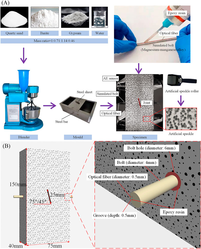
FIGURE 1. Bolted jointed specimen production process (A) and size (B).
Simulated Bolt
According to the size similarity constant
The specimen production process and size are shown in Figure 1.
Experimental System
The experimental system included a test machine, acoustic emission (AE) device, digital image correlation (DIC) device, and distributed fiber optic strain-measuring device (Figure 2).
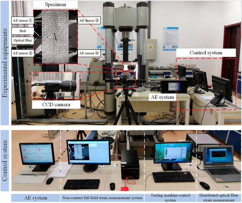
FIGURE 2. Experimental system.
Test Machine
The test machine was an RLW-3000 hydraulic servo testing machine. In these experiments, loading was applied in the displacement-controlled mode, with the loading rate of 0.2 mm/s.
AE Device
The AE sensor with a resonant frequency of 55 kHz, an operating frequency of 30–100 kHz, and a peak sensitivity of 75 dB, was adopted. Four sensors were arranged on both sides of the sample.
DIC Device
The noncontact full-field strain measurement system consisted of two parts: artificial speckle and CCD camera. In order to ensure the measurement accuracy, a fixed focus lens installed on the CCD camera was placed in front of the specimen, which ensured that the aperture and focal length were stable during the test. Artificial speckles were drawn into points with different shapes, and each of them occupied 5–10 pixels in the digital image which is beneficial to be accurately recognized. An artificial speckle pattern was produced on the front of the model, and its layout is shown in Figure 2. In addition, the light in the laboratory was also required to be extremely stable.
Distributed Fiber Optic Strain Measuring Device
The 0.5 mm diameter optical fiber was embedded into the groove of the simulated bolt using epoxy resin to ensure their synchronous deformation while loading. In this regard, the deformation of the bolt can be measured.
Experimental Results and Analysis
The anchorage effect of a rock bolt on the jointed rock mass was clarified by analyzing the stress–strain relationship, strain field distribution, AE response, and bolt strain of jointed and bolted jointed specimens.
Stress–Strain Relationship
The stress–strain curves of specimens with the joint angles being 75° and 45° under different anchorage conditions are given in Figure 3 and Supplementary Table S3. From these results, after bolting, the UCS of 75° and 45° jointed specimens increased by 16.63 and 21.54%, respectively. The peak strains of 75° and 45° jointed specimens increased by 11.11 and 10.81%, respectively. However, the elastic module of jointed samples hardly changed after the bolt was installed.
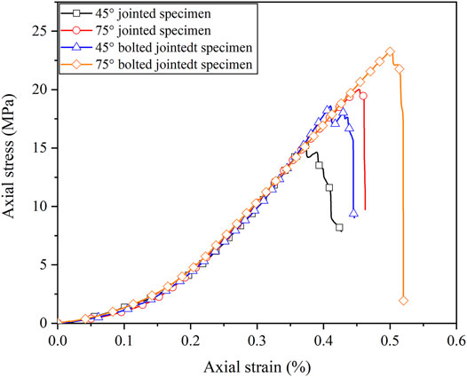
FIGURE 3. Stress–strain relationship of jointed and bolted jointed specimens.
Strain Field Distribution
The maximum principle strain under uniaxial compression actually developed along the edge of the moving zone, which might have led to the formation of wing cracks and anti-wing cracks (Figure 4). The maximum principle strain fields of jointed and bolted jointed specimens under uniaxial compression were similar to those reported by L.N.Y. Wong and Einstein (2009b). The angles of the maximum principal strain direction of jointed and bolted jointed specimens are listed in Supplementary Table S4. Because the bolt did not pass through the wing crack propagation direction, the development of the maximum principal strain in the wing crack direction was not significantly affected. Specifically, after anchoring, the angle of the maximum principal strain of 75° and 45° jointed specimens shrunk by 0.08 and 3.21% in the development direction of the wing crack, respectively. In contrast, the propagation direction of the anti-wing crack passed through the anchorage zone, which made the maximum principal strain development obstructed and shrunk closer to the anchorage zone. The angle of the maximum principal strain of 75° and 45° jointed specimens shrunk by 13.46 and 10.30% in the development direction of the anti-wing crack, respectively.
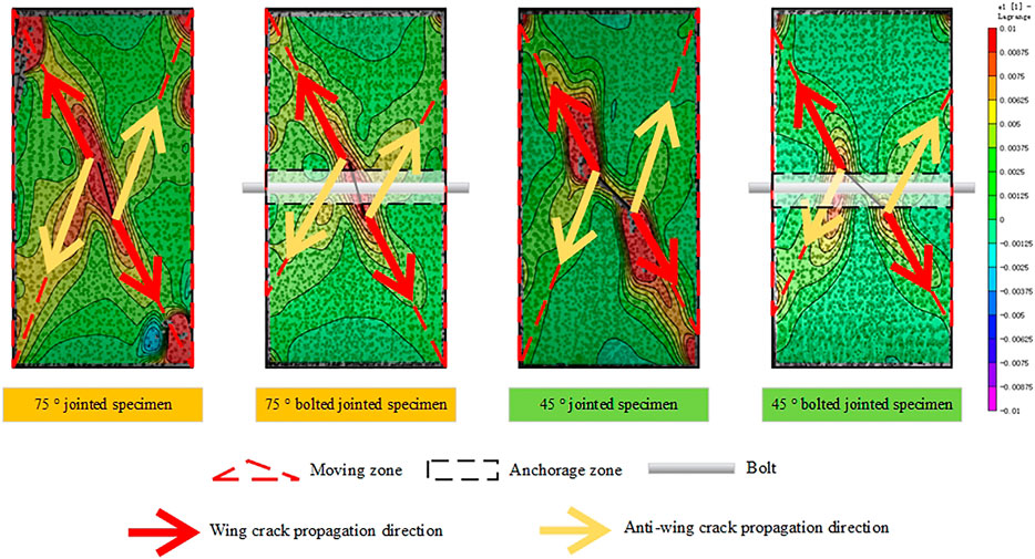
FIGURE 4. Maximum principle strain distribution of jointed and bolted jointed specimens.
AE Events
AE signals generated during the rock failure process are used to interpret the damage evolution. The crack radius can be calculated using the Brune model (J. Zhou et al., 2018; Brune 1970; J. Zhou et al., 2021) as
where
The crack radius distribution of the specimens with the joint angles of 75° and 45° is shown in Figure 5. Clearly, the radius of most cracks was between 1.5 and 3.0 mm whether the jointed specimens were anchored or not. However, the crack propagation of jointed specimens was still restrained by the bolt, which was embodied in the following aspects. First, the average crack radius of jointed specimens was larger than that of bolted jointed specimens. Second, cracks with a radius close to 9.0 mm occurred during the failure process of jointed specimens, although their number was few. In contrast, cracks with a radius over 6.0 mm were difficult to be produced during the failure process of bolted jointed specimens.
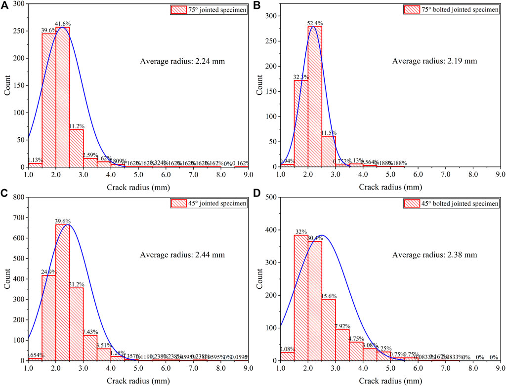
FIGURE 5. Crack radius distribution of jointed and bolted jointed specimens under uniaxial compression: (A) 75° jointed specimen, (B) 75° bolted jointed specimen, (C) 45° jointed specimen, and (D) 45° bolted jointed specimen.
The severity of the damage is reflected by the AE magnitude. The magnitude during the failure process of jointed and bolted jointed specimens was calculated by the method described according to Liu et al. (2021) (Figure 6). After anchorage, large-magnitude AE events during the compaction stage of jointed specimens became reduced. The number of AE events with a magnitude close to 8 in bolted jointed specimens was clearly less than that in jointed specimens near the instability stage. With bolt installation, the average magnitude of AE events during the failure of jointed rock specimens becomes low. This suggests that the anchorage effect reduced the severity of damage and improved the anti-disturbance capacity of jointed specimens.
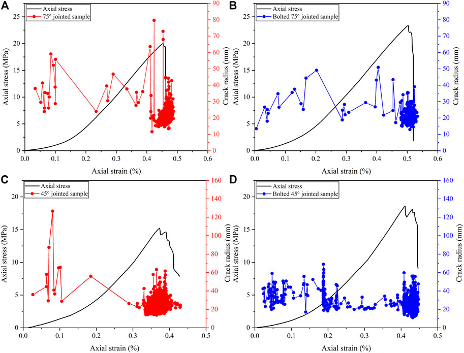
FIGURE 6. AE magnitude of jointed and bolted jointed specimens under uniaxial compression: (A) 75° jointed specimen, (B) 75° bolted jointed specimen, (C) 45° jointed specimen, and (D) 45° bolted jointed specimen.
The RA value (rising time/maximum amplitude) and average frequency (AF) of AE signals can be used to determine the tensile or shear damage modes (Soulioti et al., 2009). When
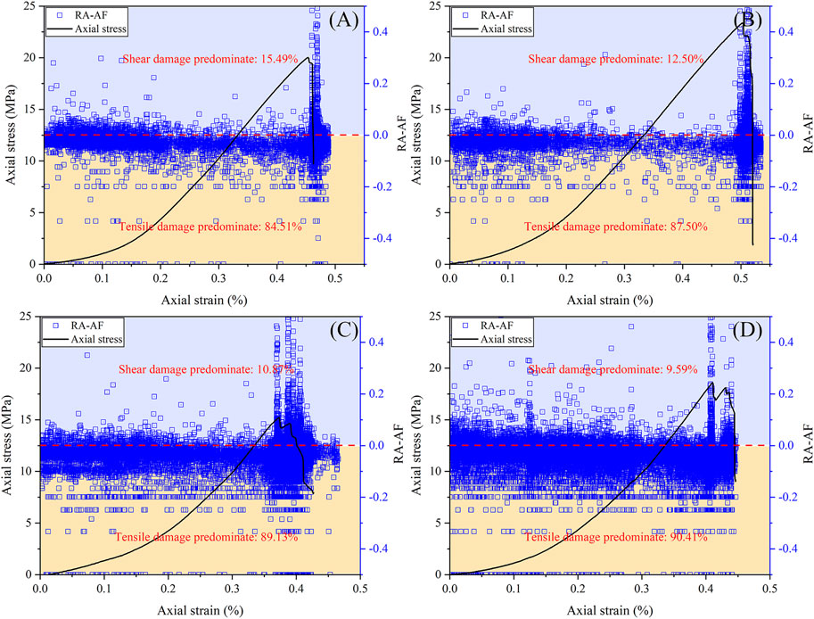
FIGURE 7. AE FA-AF of jointed and bolted jointed specimens under uniaxial compression: (A) 75° jointed specimen, (B) 75° bolted jointed specimen, (C) 45° jointed specimen, and (D) 45° bolted jointed specimen.
Under uniaxial compressive loading, the joint tip is always prone to cracking, which is due to the dislocation along the joint plane. After the jointed specimen is anchored, the cracking at the joint tip is alleviated. This is because dislocation is restrained by the bolt. As a cost, the interface between the bolt and jointed specimen becomes a location easy to crack.
Bolt Strain
Through distributed optical fiber measurements, the strain distribution along the whole length of the bolt was obtained (Figure 8). Bolt deformation in bolted jointed specimens was mainly tensile. The Mg/Mn alloy bolt is an elastic homogenous material, with an elastic modulus being 45 GPa, such that the strain in the bolt was always in tension during the tests. The tensile stress in the middle of the bolt was the highest, and the tensile stress was the lowest at both ends.
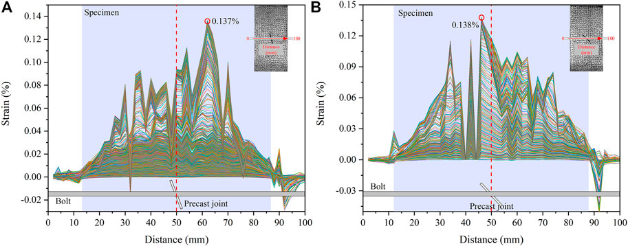
FIGURE 8. Bolt strain of bolted jointed specimen under uniaxial compression: 75° (A) and 45° (B) bolted-joint specimen.
However, the highest strain was not located at the midpoint of the bolt. In specimen bolted with a 45° joint, the peak strain was 0.138%, and its location was 4 mm away from the bolt midpoint, while the peak strain point of 75° bolted jointed specimens was 12 mm away from the midpoint, and the strain was 0.137%, which almost equaled the value of the anchorage specimen with a 45° joint. This suggested that the reinforced range of a bolt was greater in a 75° jointed specimen than in a 45° jointed specimen.
3D Numerical Simulation of the Failure Process of Bolted Jointed Rock Masses
Governing Equations
Damage Model for Rock Elements at the Mesoscale
The damage constitutive relationship of rocks under various stress states showed that damage to a rock was closely related to its stress state (Figure 9). When the rock stress state met the maximum tensile stress criterion or Mohr–Coulomb criterion, rock damage began to occur (Zhu et al., 2010). Under any stress condition, the maximum tensile stress criterion was preferred. The maximum tensile stress criterion and Mohr–Coulomb criterion were expressed as
where
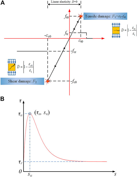
FIGURE 9. Governing equations: damage model for rock elements at the mesoscale (A) and nonlinear shear-slipping model of an anchoring interface (B).
These damage models, given as equations. (2)–(4), were implemented into FLAC3D to simulate the damage and failure of rocks under various loading conditions.
Nonlinear Shear-Slipping Model of an Anchoring Interface
In the nonlinear shear-sliding (query) model (M. Huang, Zhou, and Ou 2014), the shear stress and shear displacement relationship of the anchoring interface was
where
Suppose the residual shear strength
where
The relationship between the anchoring interface shear stress and shear displacement is shown in Figure 9.
Implementation and Results of Numerical Simulations
Boundary Conditions and Mechanical Parameters
Referring to the experimental scheme, boundary conditions of the numerical model were set. Both ends of the specimen were steel plates, and the plates and bolts were assumed to be homogenous materials.
Because rock heterogeneity was considered in numerical simulations, the damage of rock elements in a specimen should be different under the same input of Weibull distribution parameters of UCS and elastic modulus, but the failure pattern observed here was indeed similar (Zhu and Tang 2004). The mechanical parameters of the specimen are listed in Supplementary Table S3.
Numerical Simulation Results
Stress–Strain Relationship
The stress–strain relationships of jointed and bolted jointed specimens under uniaxial compression were obtained by experimental and numerical simulations (Figure 10). The elastic modulus and UCS of these specimens obtained by numerical simulation were in favorable agreement with the experimental results except that the compaction stage was neglected in the elastic damage constitutive relationship. The 3D numerical simulation method, based on the damage model for rock elements and the nonlinear shear-sliding model of the anchoring interface, was capable of describing the stress–strain relationship of jointed and bolted jointed rock masses.
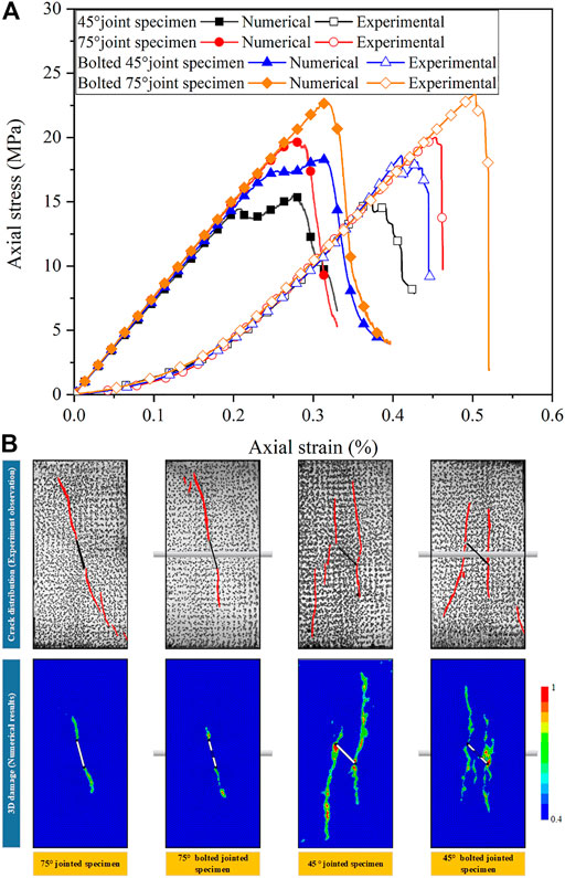
FIGURE 10. Stress–strain curves (A) and failure modes (B) of jointed and bolted jointed specimens under uniaxial compression (experimental and numerical).
Failure Mode
The final failure modes of jointed and bolted jointed specimens under uniaxial compression obtained by experimental and numerical simulation showed that cracks in 75° jointed and bolted jointed specimens were mainly wing cracks, while cracks in 45° specimens were mainly wing and anti-wing cracks (Figure 10). The damage and cracks of the jointed specimen were fully developed than those of the bolted jointed specimen when the peak stress was reached. The failure modes of specimens obtained by numerical simulation were in good agreement with the experimental results. Thus, numerical simulation appeared to be able to describe the 3D failure process of jointed and bolted jointed specimens.
Damage Evolution
Through numerical simulation, the damage evolution of jointed and bolted jointed specimens under uniaxial compression was obtained, thus showing the 3D damage process (Figure 11). After comparison, the specimens’ internal damage and bolt shear stress characteristics were deduced in the following observations:
1) To provide convenience for the following clarification, a crack initiation stress was defined as the stress when the crack began to propagate in numerical simulation. The crack initiation stress of bolted jointed specimens was greater than that of jointed specimens. The crack initiation stress of 75° jointed specimens was 90.70% of its UCS, while that of 75° bolted jointed specimens was 97.17%. The initiation stress of 45° jointed specimens was 27.20% of its UCS, while that of 45° bolted jointed specimens was 56.67%.
2) Under uniaxial compression, jointed specimens first damaged at the joint tip, resulting in wing cracks. For bolted jointed samples, the zone where the bolt passed through the joint was also very easy to damage. The transfer of the damage-prone location in the jointed specimen induced by the anchorage effect was consistent with the distribution of AE events (Figure 12). As the axial load increased, the surrounding rock in the anchorage zone was gradually destroyed, which finally led to detachment between the bolt and surrounding rock, resulting in aging of the anchorage effect.
3) When jointed and bolted jointed specimens reached the peak stress, damage in jointed specimens was clearly more developed than in bolted jointed specimens. This showed that the anchorage effect had a strong inhibitory effect on damage propagation.
4) The shear stress concentration zone of a bolt first appeared at the location where the bolt passed through the joint and gradually formed a “Z"-shaped shear stress concentration zone with the increased axial load. This was because, on one hand, the bolt restrained shear sliding along the joint plane, and on the other hand, the bolt also confined transverse deformation of the specimen.
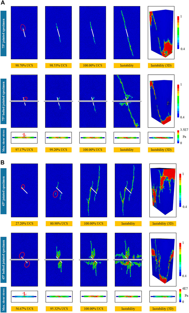
FIGURE 11. Damage evolution of jointed and bolted jointed specimens under uniaxial compression and maximum shear stress of the bolt: 75° jointed and bolted jointed specimens (A) and 45° jointed and bolted jointed specimens (B).
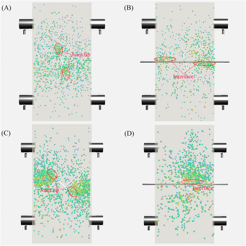
FIGURE 12. Location of AE events in jointed and bolted jointed specimens under uniaxial compression: (A) 75° jointed specimen, (B) 75° bolted jointed specimen, (C) 45° jointed specimen, and (D) 45° bolted jointed specimen.
Investigation on the Best Anchoring Strategy for Bolting Based on Numerical Simulations
The surrounding rock will deform due to tunnel excavation. To what extent the surrounding rock deforms, the best anchoring effect can be obtained by installing a bolt, which is a problem that needs further discussion. To elucidate the best anchoring strategy, bolts were installed at 0, 10, 20, 30, 40, 50, 60, 70, 80, and 90% of the peak strain of the jointed specimens. However, the UCS of jointed specimens (0% of the peak strain) bolted first and then loaded were not the highest (Figure 13 and Supplementary Table S6). For 75° jointed specimens, when loaded to 40% of the peak strain and then bolted, its UCS was the highest, their compressive strength the largest, and their anchorage effect the best. However, when loaded to 90% of the peak strain and then bolted, its UCS was lower than other bolted jointed samples, and the anchorage effect was weak. For 45° jointed specimens, the UCS was the highest, and the anchorage effect the best when the specimen was loaded to 10% of its peak strain and then bolted. When loading to 90% of the peak strain, its UCS was lower than that of other bolted jointed samples, and the anchorage effect was the weakest.
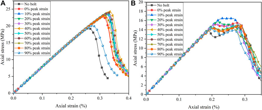
FIGURE 13. Stress–strain curves of bolted jointed specimens under different bolt installation opportunities for joint angles of 75° (A) and 45° (B).
The damage modes of bolted jointed specimens under different strain states showed that for 75° jointed specimens loaded to 40% of the peak strain and then bolted, the damage size was the smallest when the peak load was reached (Figure 14). When loaded to 90% of the peak strain and then bolted, damage developed most when reaching the peak load. For 45° jointed specimens loaded to 10% of the peak strain and then bolted, the damage size was the smallest at the peak load. When loaded to 90% of the peak strain and then bolted, damage mostly developed at the peak load.
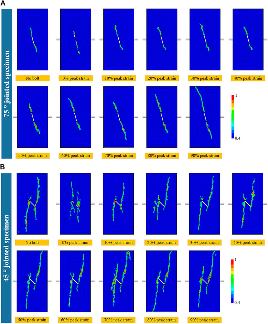
FIGURE 14. Damage mode of jointed specimens after bolting under different strain states: 75° jointed and bolted jointed specimens (A) and 45° jointed and bolted jointed specimens (B).
The aforementioned results suggest that the best support opportunity for bolting can be acquired after the surrounding rock deforms properly. If the bolt is installed when the surrounding rock begins to deform, the dislocation between the bolt and the surrounding rock might be greater than the peak shear displacement
Conclusion
The interaction between the bolt and surrounding rock and the role of the bolt on controlling the damage evolution in the jointed rock mass were investigated using a physical model test and numerical simulation. The main conclusions are as follows:
1) The compressive strength and deformation capacity of the jointed rock mass were significantly improved by the bolts. Crack propagation, shear band formation, and interface slip induced by rock damage were also constrained by bolting. Meanwhile, the damage-prone location was transferred from the joint tip to the interface between the bolt and surrounding rock.
2) The 3D progressive failure process of the bolted jointed rock mass was simulated by a developed FLAC3D code by integrating a damage model for rock elements and a nonlinear shearing-sliding model of anchored interfaces. This numerical simulation can not only reproduce experimental phenomena but also clarify internal damage propagation and the instability process in bolted jointed rock masses.
3) Numerical simulation results showed that the crack initiation stress of a bolted jointed rock mass increased significantly, but the zone where the bolt passed through the joint was also easier to damage. The damage began to propagate and penetrate gradually in the anchorage zone onset of the instability stage. In addition, the bolt formed a “Z”-shaped shear stress concentration zone observed in the bolt, which is mainly attributed to the role of the bolt in controlling the shear damage along the joint plane and transverse dilatancy of the specimen.
4) A better anchorage effect was achieved by installing bolts after the jointed rock mass deformed to a certain extent. The optimum anchorage opportunity of the jointed rock mass varied with the change of the joint angle. More specifically, for the bolted rock mass with the joint angle being 75°, the anchorage effect was best when the bolt was installed in the jointed rock mass with 40% of the peak strain, while 10% of the peak strain was perfect for the bolted rock mass with the joint angle being 45°.
Data Availability Statement
The original contributions presented in the study are included in the article/Supplementary Material, further inquiries can be directed to the corresponding author.
Author Contributions
ZY contributed to the implementation of the physical model test and the writing of the draft. WZ and KG contributed to the demonstration of the physical model test and numerical simulation scheme and the revision and approval of the draft. BY and WL contributed to the discussion and implementation of the numerical simulation method, and PL contributed to the implementation of the physical model test scheme.
Funding
The study was supported by the National Natural Science Foundation of China (Grant Nos. U1906208 and 52004053) and the Fundamental Research Funds for the Central Universities (Grant Nos. N2101028 and N2101015).
Conflict of Interest
The authors declare that the research was conducted in the absence of any commercial or financial relationships that could be construed as a potential conflict of interest.
Publisher’s Note
All claims expressed in this article are solely those of the authors and do not necessarily represent those of their affiliated organizations, or those of the publisher, the editors, and the reviewers. Any product that may be evaluated in this article, or claim that may be made by its manufacturer, is not guaranteed or endorsed by the publisher.
Supplementary Material
The Supplementary Material for this article can be found online at: https://www.frontiersin.org/articles/10.3389/feart.2022.861912/full#supplementary-material
Supplementary Table S1 | Mechanical parameters of the actual rock and mortar
Supplementary Table S2 | Mechanical parameters of the prototype rock and simulated bolts
Supplementary Table S3 | UCS and the peak strain of jointed and bolted jointed specimens
Supplementary Table S4 | Angle of the maximum principle strain direction of jointed and bolted jointed specimens
Supplementary Table S5 | Material properties of the specimen used for numerical simulation
Supplementary Table S6 | UCS of bolted jointed specimens under different bolt installation opportunities
References
Bahrani, N., and Kaiser, P. K. (2020). Influence of Degree of Interlock on Confined Strength of Jointed Hard Rock Masses. J. Rock Mech. Geotechnical Eng. 12 (6), 1152–1170. doi:10.1016/j.jrmge.2020.06.004
Brune, J. N. (1970). Tectonic Stress and the Spectra of Seismic Shear Waves from Earthquakes. J. Geophys. Res. 75 (26), 4997–5009. doi:10.1029/JB075i026p04997
Chen, F., Du, Y.-h., Sun, X.-m., Ma, T.-h., and Tang, C.-a. (2021). Numerical Experimental Study on Influence Factors of Anchoring Force of Constant Resistance Bolt. Geomatics, Nat. Hazards Risk 12 (1), 424–442. doi:10.1080/19475705.2021.1880490
Chen, F., Tang, C.-a., Sun, X.-m., Ma, T.-h., and Du, Y.-h. (2019). Supporting Characteristics Analysis of Constant Resistance Bolts under Coupled Static-Dynamic Loading. J. Mt. Sci. 16 (5), 1160–1169. doi:10.1007/s11629-018-5044-9
Chen, N., Zhang, X., Jiang, Q., Feng, X., Wei, W., and Yi, B. (2018). Shear Behavior of Rough Rock Joints Reinforced by Bolts. Int. J. Geomech. 18 (1), 04017130. doi:10.1061/(ASCE)GM.1943-5622.0001048
Chen, S.-H., Fu, C.-H., and Isam, S. (2009). Finite Element Analysis of Jointed Rock Masses Reinforced by Fully-Grouted Bolts and Shotcrete Lining. Int. J. Rock Mech. Mining Sci. 46 (1), 19–30. doi:10.1016/j.ijrmms.2008.03.002
Cheng, Long., Sun, Yaojia., Zhang, Jiyun., and Guo, Meng. (2022). .Anisotropic Characteristics of Single Jointed Rock Mass under Uniaxial Compression Technological Advancements in Construction. Cham: Springer. doi:10.1007/978-3-030-83917-8_18
Cui, G.-j., Zhang, C.-q., Chen, J.-l., Yang, F.-j., Zhou, H., and Lu, J.-j. (2020). Effect of Bolt Inclination Angle on Shear Behavior of Bolted Joints under CNL and CNS Conditions. J. Cent. South. Univ. 27 (3), 937–950. doi:10.1007/s11771-020-4342-x
Cui, S., Pei, X., Jiang, Y., Wang, G., Fan, X., Yang, Q., et al. (2021). Liquefaction within a Bedding Fault: Understanding the Initiation and Movement of the Daguangbao Landslide Triggered by the 2008 Wenchuan Earthquake (Ms = 8.0). Eng. Geology. 295, 106455. doi:10.1016/j.enggeo.2021.106455
Das, K., Deb, D., and Jha, A. K. (2012). An Enhanced Numerical Pocedure for Modelling Fully Grouted Bolts Intersected by Rock Joint. Seoul, Korea: ISRM Regional Symposium 7th Asian Rock Mechanics Symposium.
Deb, D., and Das, K. C. (2011). Enriched Finite Element Procedures for Analyzing Decoupled Bolts Installed in Rock Mass. Int. J. Numer. Anal. Meth. Geomech. 35 (15), 1636–1655. doi:10.1002/nag.970
Deb, D., and Das, K. C. (2011). Modelling of Fully Grouted Rock Bolt Based on Enriched Finite Element Method. Int. J. Rock Mech. Mining Sci. 48 (2), 283–293. doi:10.1016/j.ijrmms.2010.11.015
Du, K., Li, X., Tao, M., and Wang, S. (2020). Experimental Study on Acoustic Emission (AE) Characteristics and Crack Classification during Rock Fracture in Several Basic Lab Tests. Int. J. Rock Mech. Mining Sci. 133, 104411. doi:10.1016/j.ijrmms.2020.104411
Feng, X., Xue, F., Wang, T., Wang, L., Zhao, T., and Liu, X. (2020). Reinforcing Effects of 3D Printed Bolts on Joint-Separated Standard Soft Rock Specimens. Composites B: Eng. 193, 108024. doi:10.1016/j.compositesb.2020.108024
Gao, F. Q., and Kang, H. P. (2016). Effects of Pre-existing Discontinuities on the Residual Strength of Rock Mass - Insight from a Discrete Element Method Simulation. J. Struct. Geology. 85, 40–50. doi:10.1016/j.jsg.2016.02.010
Gao, G., Yao, W., Xia, K., and Li, Z. (2017). Application of Digital Image Correlation (DIC) Method to Dynamic Fracture Behavior of Rock Plate under Uniform Compression. 4th ISRM Young Scholars Symp. Rock Mech 5, 255–258.
Grasselli, G. (2005). 3D Behaviour of Bolted Rock Joints: Experimental and Numerical Study. Int. J. Rock Mech. Mining Sci. 42 (1), 13–24. doi:10.1016/j.ijrmms.2004.06.003
He, Y., and Kusiak, A. (2018). Performance Assessment of Wind Turbines: Data-Derived Quantitative Metrics. IEEE Trans. Sustain. Energ. 9 (1), 65–73. doi:10.1109/TSTE.2017.2715061
Huang, F., Wu, C., Ni, P., Wan, G., Zheng, A., Jang, B.-A., et al. (2020). Experimental Analysis of Progressive Failure Behavior of Rock Tunnel with a Fault Zone Using Non-contact DIC Technique. Int. J. Rock Mech. Mining Sci. 132, 104355. doi:10.1016/j.ijrmms.2020.104355
Huang, Minghua., Zhou, Zhi., and Ou, Jinping. (2014). Nonlinear Analysis on Load Transfer Mechanism of Wholly Grouted Anchor Rod along Anchoring Section. Yanshilixue Yu Gongcheng Xuebao/Chinese J. Rock Mech. Eng. 33, 3992–3997. doi:10.13722/j.cnki.jrme.2014.s2.076
Kang, H., Wu, Y., Gao, F., Jiang, P., Cheng, P., Meng, X., et al. (2016). Mechanical Performances and Stress States of Rock Bolts under Varying Loading Conditions. Tunnelling Underground Space Tech. 52, 138–146. doi:10.1016/j.tust.2015.12.005
Karampinos, E., Hadjigeorgiou, J., and Turcotte, P. (2016). Discrete Element Modelling of the Influence of Reinforcement in Structurally Controlled Squeezing Mechanisms in a Hard Rock Mine. Rock Mech. Rock Eng. 49 (12), 4869–4892. doi:10.1007/s00603-016-1080-3
Lei, G., Liu, Q., Peng, X., and Wei, L. (2020). Experimental Study on Mechanical Properties of Fractured Rock Mass under Different Anchoring Modes. Eur. J. Environ. Civil Eng. 24 (7), 931–948. doi:10.1080/19648189.2018.1429321
Li, H., Deng, J., Feng, P., Pu, C., Arachchige, D. D. K., and Cheng, Q. (2021a). Short-Term Nacelle Orientation Forecasting Using Bilinear Transformation and ICEEMDAN Framework. Front. Energ. Res. 9, 697. doi:10.3389/fenrg.2021.780928
Li, H., Deng, J., Yuan, S., Feng, P., Arachchige, D. D. K., and Arachchige, K. (2021b). Monitoring and Identifying Wind Turbine Generator Bearing Faults Using Deep Belief Network and EWMA Control Charts. Front. Energ. Res. 9, 799039. doi:10.3389/fenrg.2021.799039
Li, H., He, Y., Xu, Q., Deng, J., Li, W., and Wei, Y. (2022). Detection and Segmentation of Loess Landslides via Satellite Images: a Two-phase Framework. Landslides 1. doi:10.1007/s10346-021-01789-0
Li, Y., Li, C., Zhang, L., Zhu, W., Li, S., and Liu, J. (2017). An Experimental Investigation on Mechanical Property and anchorage Effect of Bolted Jointed Rock Mass. Geosci. J. 21 (2), 253–265. doi:10.1007/s12303-016-0043-8
Li, Y., Zhou, H., Zhang, L., Zhu, W., Li, S., and Liu, J. (2016). Experimental and Numerical Investigations on Mechanical Property and Reinforcement Effect of Bolted Jointed Rock Mass. Construction Building Mater. 126, 843–856. doi:10.1016/j.conbuildmat.2016.09.100
Lin, H., Sun, P., Chen, Y., Wang, Y., and Zhao, Y. (2020). Shear Behavior of Bolt-Reinforced Joint Rock under Varying Stress Environment. Geotech Geol. Eng. 38 (6), 5755–5770. doi:10.1007/s10706-020-01391-6
Liu, X., Zhu, W., Zhang, P., and Li, L. (2021). Failure in Rock with Intersecting Rough Joints under Uniaxial Compression. Int. J. Rock Mech. Mining Sci. 146, 104832. doi:10.1016/j.ijrmms.2021.104832
Ren, M.-y., Zhang, Q.-y., Chen, S.-y., Zhang, L.-y., Jiao, Y.-y., and Xiang, W. (2020). Experimental Study on Mechanical Properties of Anchored Rock-like Material with Weak Interlayer under Uniaxial Compression. Geotech Geol. Eng. 38 (5), 4545–4556. doi:10.1007/s10706-020-01309-2
Rubino, V., Lapusta, N., Rosakis, A. J., Leprince, S., and Avouac, J. P. (2015). Static Laboratory Earthquake Measurements with the Digital Image Correlation Method. Exp. Mech. 55 (1), 77–94. doi:10.1007/s11340-014-9893-z
Saadat, M., and Taheri, A. (2020). Effect of Contributing Parameters on the Behaviour of a Bolted Rock Joint Subjected to Combined Pull-And-Shear Loading: A DEM Approach. Rock Mech. Rock Eng. 53 (1), 383–409. doi:10.1007/s00603-019-01921-6
Soulioti, D., Barkoula, N. M., Paipetis, A., Matikas, T. E., Shiotani, T., and Aggelis, D. G. (2009). Acoustic Emission Behavior of Steel Fibre Reinforced concrete under Bending. Construction Building Mater. 23 (12), 3532–3536. doi:10.1016/j.conbuildmat.2009.06.042
Sun, X., Cui, L., Hu, J., and Zhang, Y. (2020). Experimental Study on Creep Characteristics of anchorage Rock with Cracks under cable Pulling Condition. IOP Conf. Ser. Earth Environ. Sci. doi:10.1088/1755-1315/570/2/022040
Tang, C.-a., and Xu, T. (2017). “Rock Failure Process Analysis Method (RFPA) for Modeling Coal Strata Movement,” in Advances in Coal Mine Ground Control. Editor S S. Peng (Duxford: Woodhead Publishing), 345–377. doi:10.1016/b978-0-08-101225-3.00015-3
Tong, Rui. Ming., Lu, Xian. Long., and Zheng, Wei. Feng. (2013). Experiment Study on Bolts Foundation of Large-Jointed Rock Mass in Transmission Lines. Appl. Mech. Mater. 256-259, 344–349. doi:10.4028/www.scientific.net/AMM.256-259.344
Vlachopoulos, N., Cruz, D., Tatone, B. S. A., Lisjak, A., Mahabadi, O. K., Forbes, B., et al. (2020). The Performance of Axially Loaded, Fully Grouted Rock Bolts Based on Pull-Out Experiments Utilizing Fiber Optics Technology and Associated Numerical Modelling of Such Support Elements. Geotech Geol. Eng. 38 (2), 1389–1407. doi:10.1007/s10706-019-01098-3
Wang, F., Ren, Q., Chen, B., Zou, P., Peng, Z., Hu, W., et al. (2020). Numerical Investigation on Safe Mining of Residual Pillar in Goaf: A Case Study of Panlong Lead-Zinc Mine. Geotech Geol. Eng. 38 (4), 4269–4287. doi:10.1007/s10706-020-01294-6
Wang, G., Zhang, Y., Jiang, Y., Liu, P., Guo, Y., Liu, J., et al. (2018). Shear Behaviour and Acoustic Emission Characteristics of Bolted Rock Joints with Different Roughnesses. Rock Mech. Rock Eng. 51 (6), 1885–1906. doi:10.1007/s00603-018-1438-9
Wang, Q. Y., Zhu, W. C., Xu, T., Niu, L. L., and Wei, J. (2017). Numerical Simulation of Rock Creep Behavior with a Damage-Based Constitutive Law. Int. J. Geomech. 17 (1), 04016044. doi:10.1061/(ASCE)GM.1943-5622.0000707
Wang, Y.-Q., Peng, K., Shang, X.-Y., Li, L.-P., Liu, Z.-P., Wu, Y., et al. (2021). Experimental and Numerical Simulation Study of Crack Coalescence Modes and Microcrack Propagation Law of Fissured sandstone under Uniaxial Compression. Theor. Appl. Fracture Mech. 115, 103060. doi:10.1016/j.tafmec.2021.103060
Wong, L. N. Y., and Einstein, H. H. (2009a). Crack Coalescence in Molded Gypsum and Carrara Marble: Part 2-Microscopic Observations and Interpretation. Rock Mech. Rock Eng. 42 (3), 513–545. doi:10.1007/s00603-008-0003-3
Wong, L. N. Y., and Einstein, H. H. (2009b). Systematic Evaluation of Cracking Behavior in Specimens Containing Single Flaws under Uniaxial Compression. Int. J. Rock Mech. Mining Sci. 46 (2), 239–249. doi:10.1016/j.ijrmms.2008.03.006
Xu, J., Fei, D., Yu, Y., Cui, Y., Yan, C., Bao, H., et al. (2021). Research on Crack Evolution Law and Macroscopic Failure Mode of Joint Phyllite under Uniaxial Compression. Sci. Rep. 11 (1), 4196. doi:10.1038/s41598-021-83571-9
Xu, R., and Zhou, H. (20192019). Experimental Investigation of the Anchoring Effect of Two Different Types of Rock Bolts on Fractured Rock. Adv. Mater. Sci. Eng. 2019, 1–10. doi:10.1155/2019/9290318
Xu, T., Ranjith, P. G., Wasantha, P. L. P., Zhao, J., Tang, C. A., and Zhu, W. C. (2013). Influence of the Geometry of Partially-Spanning Joints on Mechanical Properties of Rock in Uniaxial Compression. Eng. Geology. 167, 134–147. doi:10.1016/j.enggeo.2013.10.011
Yang, S.-Q., Chen, M., Huang, Y.-H., Jing, H.-W., and Ranjith, P. G. (2020). An Experimental Study on Fracture Evolution Mechanism of a Non-persistent Jointed Rock Mass with Various anchorage Effects by DSCM, AE and X-ray CT Observations. Int. J. Rock Mech. Mining Sci. 134, 104469. doi:10.1016/j.ijrmms.2020.104469
Yang, W., Wen, N.-d., Li, S., and Li, X. (2010). Experimental Study on Anchoring Effect of Rock Bolts to Fractured Rock Mass. Deep and Underground Excavations, 280–287. doi:10.1061/41107(380)38
Yin, Q., Jing, H., Su, H., and Zhao, H. (2018). Experimental Study on Mechanical Properties and Anchorage Performances of Rock Mass in the Fault Fracture Zone. Int. J. Geomech. 18 (7), 04018067. doi:10.1061/(ASCE)GM.1943-5622.0001187
Yokota, Y., Zhao, Z., Nie, W., Date, K., Iwano, K., Koizumi, Y., et al. (2020). Development of a New Deformation-Controlled Rock Bolt: Numerical Modelling and Laboratory Verification. Tunnelling Underground Space Tech. 98, 103305. doi:10.1016/j.tust.2020.103305
Yuan, Y., Xu, T., Heap, M. J., Meredith, P. G., Yang, T., and Zhou, G. (2021). A Three-Dimensional Mesoscale Model for Progressive Time-dependent Deformation and Fracturing of Brittle Rock with Application to Slope Stability. Comput. Geotechnics 135, 104160. doi:10.1016/j.compgeo.2021.104160
Zhang, L. W., Li, S. C. Li., and Wang, Y. (2007). Research on Fracture Damage Coupled with Crack Arrest by Anchorage Model of Discontinuous Jointed Rock Mass under the State of Complex Stress. Kem 348-349, 189–192. doi:10.4028/www.scientific.net/kem.348-349.189
Zhang, S., Wang, Gang., Jiang, Yujing., Wu, Xianlong., Li, Genxiao., Peng, He., et al. (2020). Study on Shear Mechanism of Bolted Jointed Rocks: Experiments and CZM-Based FEM Simulations. Appl. Sci. 10 (1), 62.
Zhang, W., Wang, L., Song, Y., and Tan, Y. (2021). Experimental Study on the Mechanical Properties of Grouted Rock Bolts Subjected to Sulfate Attack and Freeze-Thaw Cycling. Construction Building Mater. 291, 123391. doi:10.1016/j.conbuildmat.2021.123391
Zhang, Z., Liu, Y., Teng, J., Zhang, H., and Chen, X. (2020). An Investigation into Bolt Anchoring Performance during Tunnel Construction in Bedded Rock Mass. Appl. Sci. 10 (7), 2329. doi:10.3390/app10072329
Zhao, Tong-Bin., Zhang, Yu-Bao., Zhang, Qian-Qing., and Tan, Yun-Liang. (2018). Analysis on the Creep Response of Bolted Rock Using Bolted Burgers Model. Geomechanics Eng. 14 (2), 141–149.
Zhao, Z.-h., Gao, X.-j., Tan, Y.-l., and Ma, Q. (2018). Theoretical and Numerical Study on Reinforcing Effect of Rock-Bolt through Composite Soft Rock-Mass. J. Cent. South. Univ. 25 (10), 2512–2522. doi:10.1007/s11771-018-3932-3
Zhou, G.-l., Xu, T., Heap, M. J., Meredith, P. G., Mitchell, T. M., Sesnic, A. S.-Y., et al. (2020). A Three-Dimensional Numerical Meso-Approach to Modeling Time-independent Deformation and Fracturing of Brittle Rocks. Comput. Geotechnics 117, 103274. doi:10.1016/j.compgeo.2019.103274
Zhou, J., Wei, J., Yang, T., Zhang, P., Liu, F., and Chen, J. (2021). Seepage Channel Development in the crown Pillar: Insights from Induced Microseismicity. Int. J. Rock Mech. Mining Sci. 145, 104851. doi:10.1016/j.ijrmms.2021.104851
Zhou, J., Wei, J., Yang, T., Zhu, W., Li, L., and Zhang, P. (2018). Damage Analysis of Rock Mass Coupling Joints, Water and Microseismicity. Tunnelling Underground Space Tech. 71, 366–381. doi:10.1016/j.tust.2017.09.006
Zhu, W. C., Li, Z. H., Zhu, L., and Tang, C. A. (2010). Numerical Simulation on Rockburst of Underground Opening Triggered by Dynamic Disturbance. Tunnelling Underground Space Tech. 25 (5), 587–599. doi:10.1016/j.tust.2010.04.004
Keywords: anchorage effect, bolted jointed rock mass, physical model test, 3D numerical simulation, acoustic emission
Citation: Yang Z, Zhu W, Guan K, Yan B, Luo W and Liang P (2022) Experimental and Numerical Study on the Anchorage Effect of Bolted Jointed Rock Masses. Front. Earth Sci. 10:861912. doi: 10.3389/feart.2022.861912
Received: 25 January 2022; Accepted: 07 February 2022;
Published: 17 March 2022.
Edited by:
Yusen He, Grinnell College, United StatesReviewed by:
Gang Huang, Wuchang University of Technology, ChinaYong Niu, Shaoxing University, China
Copyright © 2022 Yang, Zhu, Guan, Yan, Luo and Liang. This is an open-access article distributed under the terms of the Creative Commons Attribution License (CC BY). The use, distribution or reproduction in other forums is permitted, provided the original author(s) and the copyright owner(s) are credited and that the original publication in this journal is cited, in accordance with accepted academic practice. No use, distribution or reproduction is permitted which does not comply with these terms.
*Correspondence: Kai Guan, Z3VhbmthaUBtYWlsLm5ldS5lZHUuY24=