 Yuan Fengjie
 Liu Yang2
 Xu Qianwei
 Cui Yuebang
- 1The Fifth Engineering Company of CREGC, Chengdu, China
- 2Chongqing Survey Institute, Chongqing, China
- 3School of Transportation Engineering, Tongji University, Shanghai, China
- 4Chongqing Urban Construction Investment (Group) Co.Ltd, Chongqing, China
- 5China Railway No.2 Engineering Group Co., Ltd, Chengdu, China
In tunnel engineering, newly built tunnels will disturb the surrounding strata and close-to-existing tunnels, which may cause secondary lining cracking and overall damage to existing tunnels. In this paper, combined with the engineering problem of longitudinal cracks in the secondary lining of the lower tunnel caused by the super-close construction of a new tunnel in Chongqing, China, the deformation laws of the tunnel vault, inverted arch, and transverse brace during the construction of an overlapping tunnel are studied by using the finite element method. According to the distribution characteristics of stratum shear stress and plastic zone, the stratum and tunnel disturbance are analyzed. At the same time, combined with the field records, the causes and distribution laws of longitudinal cracks in the lower tunnel lining are explored. The research results show that the main reason for the cracking of the secondary lining is the bias effect of the post-excavation tunnel construction on the lower tunnel. When the tunnel spacing is small, the stratum maximum shear stress is concentrated, the penetration of the plastic deformation zone is more connected, and the settlement of the vault, horizontal convergence, and the deformation of the upper part of the arch waist of the lower tunnel are more intensified. This short-distance bias action causes the deformation of the stratum and the tunnel and eventually cracks in the lining.
1 Introduction
With the continuous development of tunnel construction, it is inevitable to encounter the problem of imminent disturbance caused by the construction of new tunnels in super-close disturbance parallel to the existing lower tunnel. Designers and engineers must analyze the mechanics and deformation behavior of the stratum and the tunnel caused by the excavation of the upper and lower overlapped tunnels, especially the impact of the post-excavation tunnel on the first excavated tunnel and stratum, which will help the safe construction and operation of the upper and lower overlapping tunnels.
Many scholars have conducted relevant research on the construction mechanics effects of tunnels adjacent to existing structures.
On the one hand, the excavation of tunnels close to building structures (foundation pits or tunnels) could have an impact. Based on the engineering example of a newly built shield tunnel that traverses an existing tunnel underneath, Li (Peng et al., 2014) studied vertical displacement and longitudinal stress changes of existing tunnels on the effects of new tunnels. Do et al. (2015) investigated the structural mechanical properties and deformation characteristics of the existing tunnel under the condition of the change in the distance between the tunnels. Yun et al. (2014) developed an application program that can use actual field monitoring based on the principal component analysis method (PCA), which can be used to monitor the behavior of the tunnel structure and prevent large deformations and even cracking. Based on the engineering example of a new tunnel under the double tunnel, Cooper et al. (2001) constructed an empirical equation through theoretical analysis to predict the settlement and suggested using it as a preliminary forecasting tool. In addition, the data of three parallel tunnels were combined for verification and analysis, and it was proposed that the loss of ground stiffness would lead to the volume loss of the existing tunnels. Zhang and Huang (2014) studied the ground and structural disturbances caused by the interaction mechanics of multi-line overlapping tunnels in China. Through numerical simulation and on-site monitoring, Standing et al. (2015) analyzed the dynamic response of the upper tunnel lining structure’s cast iron segment joints to the new lower tunnel. Liang et al. (2013) studied the dynamic response of the blasting vibration of the new railway tunnel to the adjacent existing railway tunnel and analyzed the influence of the existing tunnel lining structure before and after the blasting vibration, which was of reference significance for analyzing and controlling cracks in the secondary lining. Zhao et al. (2016) carried out experimental and numerical simulation studies on the influence of blasting vibration of adjacent tunnels on existing tunnels and analyzed the axial and radial mechanical responses of existing tunnels. Hage Chehade and Shahrour (2008) established a two-dimensional model to analyze the mechanical response of tunnel construction under the different relative positions. Addenbrooke and Potts (2001) analyzed the ground deformation caused by the construction of the double tunnel and the mechanical behavior of the tunnel lining. Asano et al. (2003) put forward the observation and excavation control measures for the nearby existing mountain tunnels through the combination of the investigation results from the fault zone and simulation results from finite element analysis. Byun et al. (2006) conducted a scaled model test to study the mechanical behavior of the stratum and tunnel caused by the new upper-level tunnel and analyzed the longitudinal arch effect and stress flow disturbance of the lower tunnel caused by the upper tunnel.
On the other hand, the construction of building structures adjacent to the tunnel could have an impact. Zheng and Wei (2008) used a two-dimensional model to study the response of the existing tunnel caused by the excavation of the overlying soil. Schroeder et al. (2004) used numerical simulation to predict the impact of pile group load on existing tunnels to ensure the acceptance and deformation safety of the tunnel structure. Beyabanaki and Gall (2017) studied the mechanical response and deformation characteristics of foundation pit excavation to the existing tunnel underneath and analyzed the internal force and deformation stability of the lower tunnel lining. Shin et al. (2011) simulated and analyzed soft rock tunnels through the establishment of a dynamic simulation model. By establishing the finite element model, Liu et al. (2011) carried out research on the disturbance effects and control measures of the construction of the new open-cut tunnel. Park et al. (2018) analyzed the influence of the excavation damage zone caused by blasting on the overall stability of the tunnel. Dolezalova (Marta, 2001) analyzed the deformation and stress changes of a group of subway tunnels in an open-air excavation environment. Hu et al. (2003) and Jia (2006) studied the effects of different tunnel excavation methods and construction control measures based on field measurements. Sharma et al. (2001) investigated the construction deformation disturbance of two parallel tunnels using on-site monitoring results and found that there was a significant coupling effect between the two.
Moreover, there has been related research work on tunnel lining cracks. Dong et al. (2019) and others established a model that integrates basic SegNet and focal loss functions through deep learning (DL) technology, which improves the distribution prediction ability of small cracks and overlapping damage in tunnel linings. Huang et al. (2018) proposed a new image recognition algorithm based on deep learning for visual inspection of tunnel cracks and leakage defects. Qu (Zhong et al., 2016) researched the detection and repair methods of concrete tunnel lining surface cracks. An improved seepage detection algorithm aims at the detection of concrete tunnel lining surface cracks.
In summary, there have been a large number of studies on the interaction between the construction of a tunnel and close-to-existing buildings or structures (including tunnels). However, so far, there have been few studies on the construction disturbance effect of the upper and lower overlapped tunnels. In this paper, the stress and deformation behavior of the stratum and tunnel during the construction of overlapping tunnels are studied. The cause and distribution of the longitudinal cracks in the secondary lining of the lower tunnel are analyzed.
2 Project Overview
2.1 Design Overview
The upper and lower adjacent overlapping tunnels in this study are shown in Figure 1. The maximum buried depths of the vault of the upper and lower tunnels are 130 and 149 m, respectively, and the longitudinal position relationship is shown in Figure 2. The tunnel area is mainly woodland with an elevation of 217.9–302.3 m. The minimum height difference between the upper and lower tunnel track surfaces in the tunnel mileage section of this study is about 14.3 m, and the minimum net rock layer is about 2.5 m. The entire section is located on a straight line, and a single-sided slope with a longitudinal slope of 3% is designed.
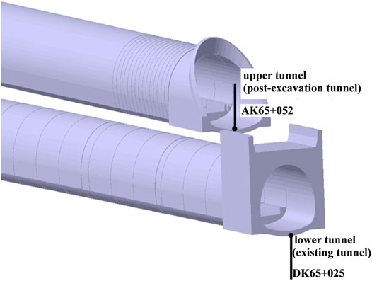
FIGURE 1. Schematic diagram of the spatial location of the Bajiaogou overlapping tunnels
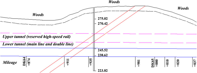
FIGURE 2. Longitudinal relationship diagram of the upper and lower tunnels.
The tunnel is excavated by the mining method and supported in advance by the large pipe shed. In general, the construction is carried out from the bottom to the top, and after the construction of the lower tunnel is completed, the construction of the upper tunnel will be carried out. Figure 3 shows the construction diagram of the upper and lower tunnels, which are constructed by the two-step temporary inverted arch method, with temporary cross bracing. The initial support of the upper and lower tunnels is C25 shotcrete with a thickness of 30 and 27 cm, respectively, and the lining is C35 reinforced concrete with a thickness of 55 and 70 cm, respectively.
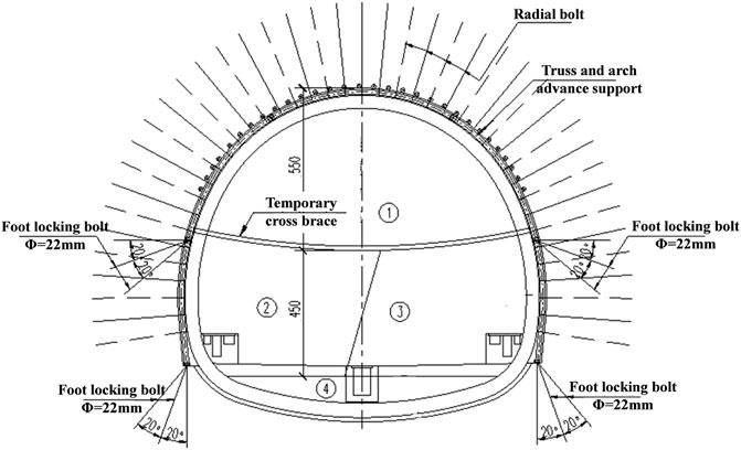
FIGURE 3. Construction process of a double-track tunnel step method with temporary transverse bracing.
2.2 Engineering Geology
The stratum in the tunnel area is a monoclinic structure with a complex geological structure and poor geological development, mainly including accumulations, coal seam gas, soft rock, and trench soft soil. The overall surrounding rock of the tunnel is relatively soft, the joint fissures are relatively developed, and it is covered with artificially filled soil, silty clay, and silty clay. The surface water in the site area is mainly gully water, which is recharged by atmospheric rainfall, while the groundwater is mainly poured water and fissure water, which is mainly recharged by infiltration such as atmospheric rainfall. It has little impact on concrete and tunnel construction.
3 Numerical Simulation Establishment of Overlapping Tunnels
3.1 Typical Cross Sections of Upper and Lower Overlap Tunnels
The vertical spacing between the upper and lower tunnels is about 2∼5 m, the horizontal spacing is about 0–22 m, and the buried depth of the upper tunnels gradually increases from 3 to 75 m. Five typical sections in the study section are selected for research. The relative position relationship between the upper and lower tunnels is shown in Figure 4, and the corresponding buried depth and spacing are shown in Table 1.
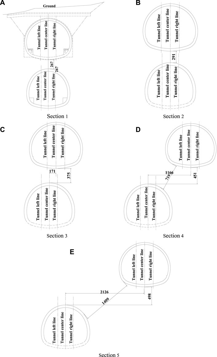
FIGURE 4. Typical cross section of the overlapped tunnels (unit: mm).
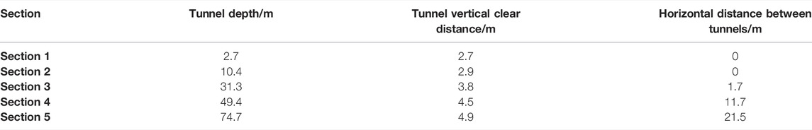
TABLE 1. Information table of each section.
3.2 Numerical Simulation of Overlapping Tunnels
The interaction between the stratum and the structure is analyzed and studied by finite element numerical simulation. Taking into account the range of interaction between the research object and the surrounding soil, select the influence range of tunnel excavation (3–5 times the tunnel radius). According to the relevant design data, the mechanical parameters of the rock mass around the tunnel section are selected. In the calculation model, the surrounding rock is simulated by the two-dimensional elements of the Mohr-Coulomb constitutive model. The secondary lining is simulated by linear elastic constitutive two-dimensional elements. One-dimensional beam elements with an elastic constitutive model are adopted for concrete and temporary cross braces. In some cases, bolt support can be equivalent to soil reinforcement in numerical simulation. The detailed values of the material parameters of the model are shown in Table 2.
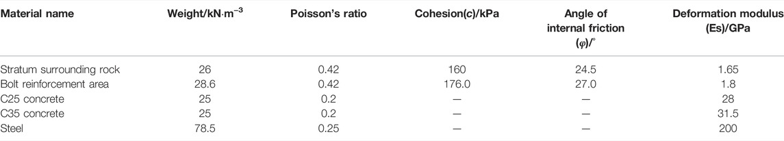
TABLE 2. Physical and mechanical parameters of model materials.
Set the normal displacement constraint boundary on the side and bottom of the model, and the boundary on the top of the model is a free surface. As shown in Figure 5, take Section 4 as an example to illustrate the numerical simulation grid division of the model. The model is 110 m long and 118 m high. The upper and lower tunnel excavation zones and the secondary lining model are shown in Figure 6.
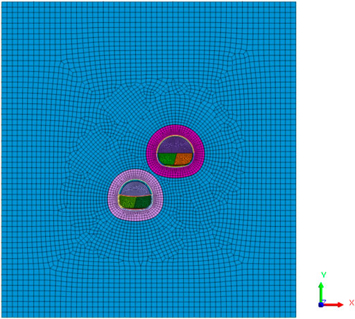
FIGURE 5. Two-dimensional finite element calculation model.
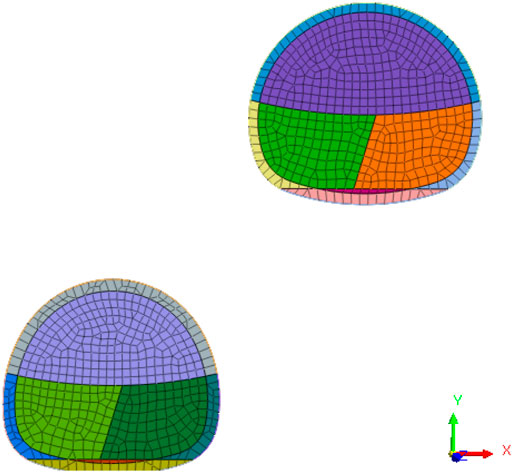
FIGURE 6. Anchor rod equivalent reinforcement area and secondary lining model.
3.3 Simulation of Excavation Conditions
According to the actual working conditions, the lower tunnel is first excavated, and then the upper tunnel is excavated. The construction sequence of the two tunnels is shown in Table 3. According to the overlap, the tunnel construction process is divided into 12 construction stages according to the simulation of key steps.
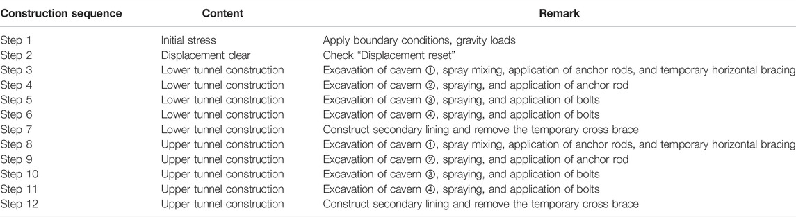
TABLE 3. A brief description of the construction steps of the sequential construction method.
4 Model Result Analysis
4.1 Vertical Displacement
Take Section 4 as an example to present the simulation results and analyze them. Figure 7 shows the vertical displacement cloud image caused by the completion of Step12. During the excavation of tunnels, arch crown settlement and arch bottom uplift will occur. After the construction of the upper tunnel, the vault settlement of the lower tunnel increased from 8.9 to 9.7 mm, an increase of 9%, compared with the results of step 7. And the distribution of stratum settlement is asymmetric, and the settlement trend is inclined below the joint action of the upper and lower tunnels.
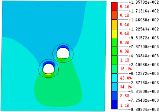
FIGURE 7. Vertical displacement after excavation of the upper tunnel (unit: m).
4.2 Horizontal Displacement
Figure 8 shows the horizontal displacement cloud diagram caused by the completion of Step12. During the excavation of the tunnel, the arch waist and the area above it will produce horizontal deformation, which can increase the potential factors of the secondary lining tension cracking. After the construction of the upper tunnel, the horizontal deformation of the arch waist and above the lower tunnel increased from 10.7 to 11.3 mm, an increase of 6%, and the horizontal convergence increased from 23.2 to 25.6 mm, an increase of 10%, compared with the results of step 7. It can be seen that the horizontal convergence deformation of the arch waist and the area above increased due to the construction of the upper tunnel.
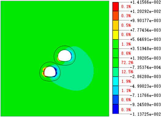
FIGURE 8. Horizontal displacement after excavation of the upper tunnel (unit: m).
4.3 Maximum Formation Shear Stress
Figure 9 shows the maximum stress cloud image caused by the completion of Step12. During the excavation of the tunnel, there is a concentration of shear stress around the tunnel, which is mainly concentrated in the range of 3–8 m around the tunnel, that is, around the end of the anchor rod. Therefore, in actual construction, the quality of the anchor rod should be ensured, especially the depth of the anchor rod and the stability of the soil near the tunnel. At the same time, the shear stress concentration area at the stratum connection part is significantly higher than that of the surrounding stratum, which means that the stratum soil in this area will be damaged first, and it should be properly reinforced during construction. In addition, the shear stress concentration of the lower tunnel is mainly concentrated above the arch waist, which is close to the secondary lining crack found on site.
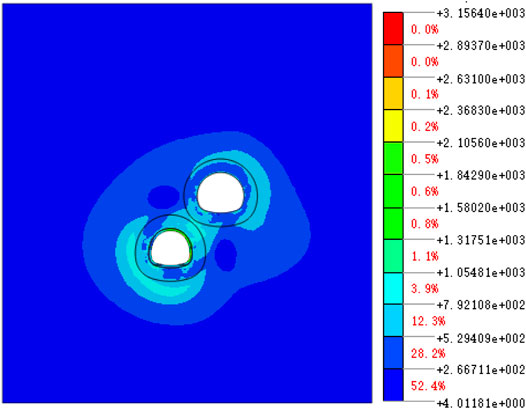
FIGURE 9. Maximum shear stress after excavation of the upper tunnel (unit: kPa).
4.4 Plastic Zone Distribution
Figure 10 shows the distribution cloud map of the formation plastic zone caused by the completion of Step12. Part of the plastic zone appears around the tunnel excavation area, and it is easy to form a penetrating plastic zone between the upper and lower tunnels. Moreover, the plastic zone of the lower tunnel is mainly located above the arch waist on both sides, which is also consistent with the location of the shear stress concentration. The plastic zone reflects the distribution of rock mass instability and failure, especially at the stratum connection. The distribution of the plastic zone is relatively obvious, and there is serious penetration. Therefore, in the actual construction, one needs to pay attention to the proper reinforcement of the rock mass at the connection between the upper and lower tunnels to avoid the penetration of the plastic zone.
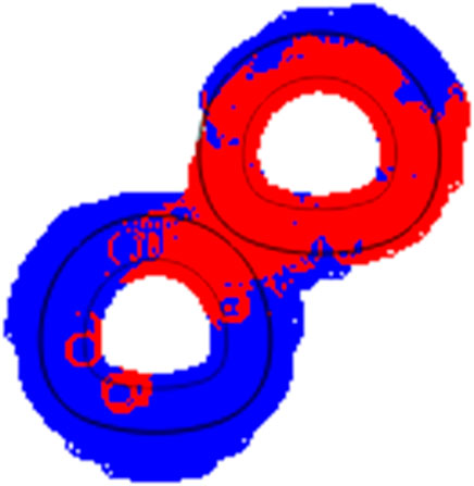
FIGURE 10. Distribution of the plastic zone after excavation of the upper tunnel (red: plastic or failure; blue: unloading or reloading).
4.5 Secondary Lining Stress
Figure 11 shows the vertical stress distribution cloud diagram of the secondary lining caused by the completion of Step 12. It can be seen that the tensile stress of the secondary lining of the lower tunnel appears to stress concentration near the left and right arch waists, and the maximum tensile stress in the Y direction is 4.15 and 4.46 mpa, respectively. The tensile stress distribution of the left and right arch waist is significant.
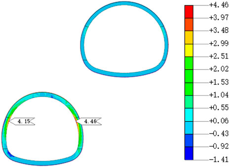
FIGURE 11. Y-direction stress of the secondary lining structure of the lower tunnel (unit: MPa).
5 Analysis of the Cracks in the Lining Structure of the Lower Tunnel
5.1 Actual Lining Cracks
According to the actual measurement on site, after the construction of the upper tunnel (post-excavation tunnel) was completed, longitudinal cracks appeared in some areas of the lower tunnel (existing tunnel). As shown in Figure 12, the cracks occurred mainly at the right waist of the lower tunnel, which was adjacent to the upper tunnel. As shown in Figure 13, cracks appeared in both the left and right arches of the lower tunnel. Table 4 has given the specific conditions of the cracks. It can be found that the crack length is 12 m, the crack width is 0.2∼0.4 mm, and the crack depth is 7.7∼12.5 cm.
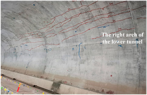
FIGURE 12. Site photo of the partial longitudinal crack on the right side of the lower tunnel.
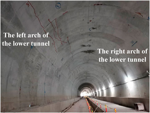
FIGURE 13. Site photos of longitudinal cracks on the left and right sides of the lower tunnel.

TABLE 4. Crack situation table
5.2 Analysis of the Causes of Cracks
When comparing the tensile stress calculation result of the obvious tensile area of the secondary lining of the lower tunnel caused by the construction of the upper tunnel with the standard value of the tensile strength of C35 concrete of 2.2 MPa, it can be found that the maximum tensile stress of the secondary lining of the lower tunnel obtained by the cross-section simulation calculation is greater than 2.2 MPa, so cracks extending along the Z direction in the XY plane will occur, which appear as longitudinal cracks.
Although the above is a quantitative judgment, to further analyze the development law of tunnel cracks caused by construction mechanical properties, it is necessary to analyze the cause and law of the secondary lining cracks of the lower tunnel based on the characteristics of stratum deformation and the distribution law of stratum shear stress and plastic zone.
Figure 14 shows the tunnel displacement curve of each section after the completion of step 12, and Figure 15 shows the absolute change rate of the influence of the upper tunnel on the lower tunnel, in which the tunnel buried depth, tunnel vertical clear distance, and tunnel horizontal distance from Section 1 to Section 5 gradually increase. According to Figures 14, 15, in terms of vault settlement, when the buried depth is shallow and the tunnel distance is close, the construction of the upper tunnel will rebound the vault settlement of the lower tunnel to a certain extent, in which Section 1 rebounds by 12%. With the increase in the distance between the two tunnels, it will gradually increase the vault settlement of the lower tunnel, in which Section 5 settlement increases by 7%. In terms of invert displacement, the influence of the upper tunnel construction on the invert of the lower tunnel uplift is relatively small, of which Section 1 has the largest change rate, and the uplift is only increased by 5%. In terms of horizontal convergence, the construction of the upper tunnel will lead to an increase in the horizontal displacement of the lower tunnel. The greater the distance between the two tunnels, the greater the increase and the maximum increase is 11%. It can be seen that the vault settlement and horizontal convergence of the lower tunnel at different sections are mainly affected, while the inverted arch has little effect. Considering the vertical deformation of the arch crown and the horizontal deformation of the arch waist, greater oblique deformation above the arch waist will be obtained. The deformation law of the upper part of the arch waist reflects the causes of the cracks in the lower tunnel.
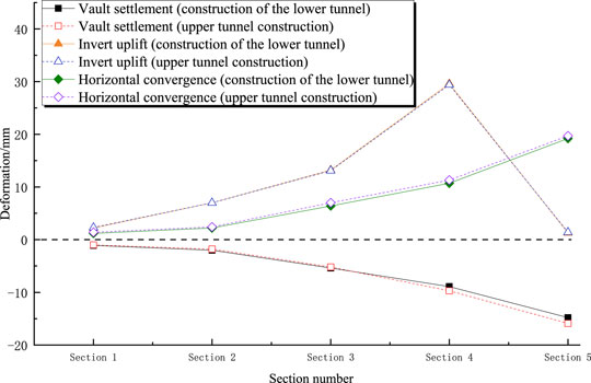
FIGURE 14. Displacement result analysis at different cross-sections
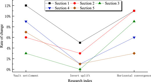
FIGURE 15. Displacement result analysis at different cross-sections
Figure 16 shows the maximum shear stress distribution of different sections after step 12. It can be seen that the shear stress is mainly concentrated in the range of 3∼8 m around the tunnel. In this range, the overlapped tunnel arrangement has the greatest influence, and the most significant part is still in the upper part of the lower arch. As the upper and lower tunnels are gradually staggered on the plane, this influence gradually weakens, and as the distance increases and staggers, the maximum shear stress is gradually distributed in the area between the two tunnels, and the influence of the right arch of the lower tunnel is more obvious than that of the left arch.
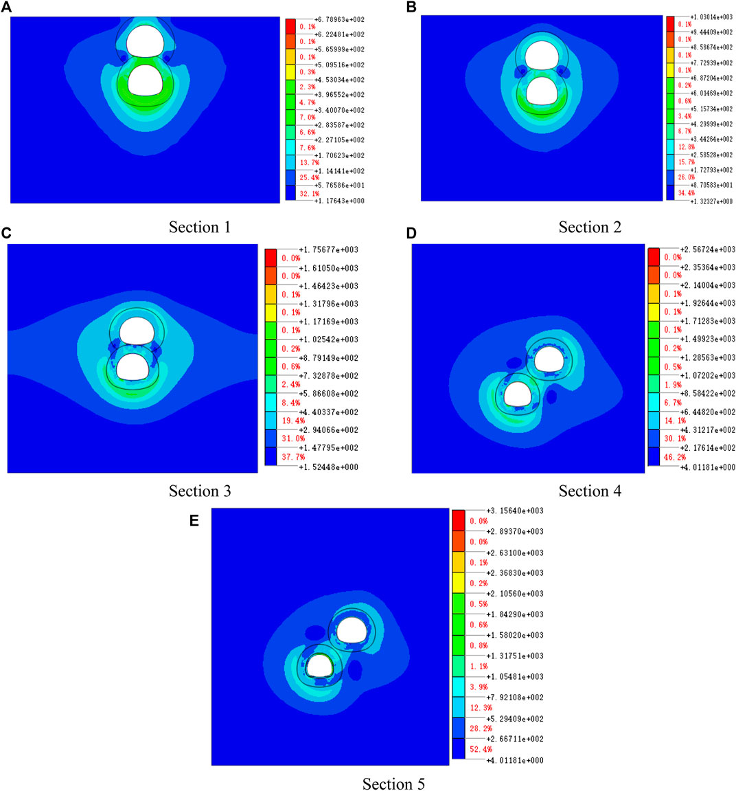
FIGURE 16. Maximum shear stress cloud diagram of displacement at different cross-sections (unit: kPa).
5.3 Crack Distribution Law
1) The characteristics of tunnel displacement and the distribution of shear stress indicate that there is a greater risk of cracks near the left and right arch waists of the lower tunnel, which not only reflects the location of the cracks, but also explains the reasons for the changes in the cracks.
2) The distribution trend of the maximum shear stress shows that the bias effect of the upper tunnel on the lower tunnel increases with the decrease in the distance between the tunnels. The bias effect decreases with the increase of distance, and the lining cracks of the lower tunnel appear gradually.
3) The change rate of the deformation influence of the lower tunnel decreases with the increase in the distance between the two tunnels. Under the large lining deformation, the lower tunnel is easy to crack in the arch’s waist and upper part.
6 Conclusion
In this paper, aiming at the longitudinal cracks in the secondary lining of the tunnel, numerical simulation is used to analyze the mechanical response of the construction of the upper and lower overlapping tunnels. The causes and distribution laws of longitudinal cracks in the lower tunnel lining are explored. The following conclusions are drawn:
1) The vault settlement and horizontal convergence are the main influences of the upper tunnel on the lower tunnel are. The deformation law of the upper part of the larger arch waist constitutes the cause of the cracks in the lower tunnel, and the arch waist on the side close to the tunnel is easily cracked. Therefore, the construction should focus on the deformation of the vault and arch waist.
2) As the distance between overlapping tunnels increases from near to far, the influence of the upper tunnel construction on the lower tunnel is that the horizontal convergence deformation increases gradually, and the vertical deformation changes from the rebound to intensified settlement.
3) The maximum shear stress and plastic deformation area have similar distribution laws. If the distance between the tunnels is too small, it will produce obvious shear stress concentration and increase the penetration degree of the plastic zone, resulting in high stress on the lower tunnel lining, reflecting the corresponding relationship between the maximum shear stress distribution area, the plastic area and the crack distribution of the lower tunnel.
4) The stress and deformation characteristics of the stratum and lining structure reflect that the post-excavation tunnel has a biasing effect on the existing tunnel, which constitutes the cause of tunnel cracks. Measures should be taken in time to weaken this effect during construction to avoid tunnel cracks.
Data Availability Statement
The original contributions presented in the study are included in the article/Supplementary Material, further inquiries can be directed to the corresponding author.
Author Contributions
YF and LY: Georisjk analysis; XQ: numerical simulation; ZY: georisk analysis; HL: crack analysis; ZP: construction control; and CY: numerical simulation.
Conflict of Interest
Authors YF and ZP were employed by The Fifth Engineering Company of CREGC; author ZY was employed by Chongqing Urban Construction Investment (Group) Co., Ltd.; and author HL was employed by China Railway No. 2 Engineering Group Co., Ltd.
The remaining authors declare that the research was conducted in the absence of any commercial or financial relationships that could be construed as a potential conflict of interest.
Publisher’s Note
All claims expressed in this article are solely those of the authors and do not necessarily represent those of their affiliated organizations, or those of the publisher, the editors, and the reviewers. Any product that may be evaluated in this article, or claim that may be made by its manufacturer, is not guaranteed or endorsed by the publisher.
References
Addenbrooke, T. I., and Potts, D. M. (2001). Twin Tunnel Interaction: Surface and Subsurface Effects. Int. J. Geomech. 1 (2), 249–271. doi:10.1061/(asce)1532-3641(2001)1:2(249)
Asano, T, Ishihara, M., Kiyota, Y., Kurosawa, H., and Ebisu, S. (2003). An Observational Excavation Control Method for Adjacent Mountain Tunnels[J]. Tunn. Undergr. Space Technol. 18 (2-3), 291–301. doi:10.1016/s0886-7798(03)00043-9
Beyabanaki, A.R., and Gall, V. (2017). 3D Numerical Parametric Study of the Influence of Open-Pit Mining Sequence on Existing Tunnels [J]. Int. J. Min. Sci. Technol. 27 (03), 459–466.
Byun, G., Kim, D., and Lee, S. (2006). Behavior of the Ground in Rectangularly Crossed Area Due to Tunnel Excavation under the Existing Tunnel[J]. Tunn. Undergr. Space Technol. 21 (3-4), 361–367. doi:10.1016/j.tust.2005.12.178
Cooper, M.L., Chapman, D.N., and Rogers, C.D.F. (2001). Prediction of Settlement in Existing Tunnel Caused by the Second of Twin Tunnels[J]. Transp. Res. Rec. 1814 (1), 103–111. doi:10.3141/1814-12
Do, N.-A., Dias, D., and Oreste, P. (2015). 3D Numerical Investigation on the Interaction between Mechanized Twin Tunnels in Soft Ground. Environ. Earth Sci. 73 (5), 2101–2113. doi:10.1007/s12665-014-3561-6
Dong, Y., Wang, J., Wang, Z., Zhang, X., Gao, Y., Sui, Q., et al. (2019). A Deep-Learning-Based Multiple Defect Detection Method for Tunnel Lining Damages. IEEE Access 7, 182643–182657. doi:10.1109/access.2019.2931074
Hage Chehade, F., and Shahrour, I. (2008). Numerical Analysis of the Interaction between Twin-Tunnels: Influence of the Relative Position and Construction Procedure. Tunn. Undergr. Space Technol. 23 (2), 210–214. doi:10.1016/j.tust.2007.03.004
Hu, Z. F., Yue, Z. Q., Zhou, J., and Tham, L. G. (2003). Design and Construction of a Deep Excavation in Soft Soils Adjacent to the Shanghai Metro Tunnels. Can. Geotech. J. 40 (5), 933–948. doi:10.1139/t03-041
Huang, H.-w., Li, Q.-t., and Zhang, D.-m. (2018). Deep Learning Based Image Recognition for Crack and Leakage Defects of Metro Shield Tunnel. Tunn. Undergr. Space Technol. 77, 166–176. doi:10.1016/j.tust.2018.04.002
Jia, J. (2006). Study of Controlling Measures on the Deflection of Metro Tunnels Due to Overlying Excavation[J]. Undergr. Constr. Ground Mov. 26 (s), 158–163. doi:10.1061/40867(199)18
Liang, Q., Li, J., Li, D., and Ou, E. (2013). Effect of Blast-Induced Vibration from New Railway Tunnel on Existing Adjacent Railway Tunnel in Xinjiang, China. Rock Mech. Rock Eng. 46 (1), 19–39. doi:10.1007/s00603-012-0259-5
Liu, H., Li, P., and Liu, J. (2011). Numerical Investigation of Underlying Tunnel Heave during a New Tunnel Construction. Tunn. Undergr. Space Technol. 26 (2), 276–283. doi:10.1016/j.tust.2010.10.002
Marta, D. O. L. E. Z. A. L. O. V. A. (2001). Tunnel Complex Unloaded by a Deep Excavation[J]. Comput. Geotechnics 28 (3), 69–493. doi:10.1016/S0266-352X(01)00005-2
Park, S., Kim, J.-S., and Kwon, S. (2018). Investigation of the Development of an Excavation Damaged Zone and its Influence on the Mechanical Behaviors of a Blasted Tunnel. Geosystem Eng. 21 (3), 165–181. doi:10.1080/12269328.2018.1461139
Peng, L., Du, S., Ma, Xi., Yin, Z., and Shen, S. (2014). Centrifuge Investigation into the Effect of New Shield Tunnelling on an Existing Underlying Large-Diameter Tunnel. Tunn. Undergr. Space Technol. 42, 59–66. doi:10.1016/j.tust.2014.02.004
Schroeder, F. C., Potts, D. M., and Addenbrooke, T. I. (2004). The Influence of Pile Group Loading on Existing Tunnels. Géotechnique 54 (6), 351–362. doi:10.1680/geot.2004.54.6.351
Sharma, J. S., Hefny, A. M., Zhao, J., and Chan, C. W. (2001). Effect of Large Excavation on Deformation of Adjacent MRT Tunnels. Tunn. Undergr. Space Technol. 16 (2), 93–98. doi:10.1016/s0886-7798(01)00033-5
Shin, J.-H., Moon, H.-G., and Chae, S.-E. (2011). Effect of Blast-Induced Vibration on Existing Tunnels in Soft Rocks. Tunn. Undergr. Space Technol. 26 (1), 51–61. doi:10.1016/j.tust.2010.05.004
Standing, J. R., Potts, D. M., Vollum, R., Burland, J. B., and Avgerinos, V. (2015). Research into the Effect of Tunneling on Existing Tunnels[J]. Infrastructure 2 (59), 301–312. doi:10.1680/ecsmge.60678
Yun, H.-B., Park, S.-H., Mehdawi, N., Mokhtari, S., Chopra, M., Reddi, L. N., et al. (2014). Monitoring for Close Proximity Tunneling Effects on an Existing Tunnel Using Principal Component Analysis Technique with Limited Sensor Data. Tunn. Undergr. Space Technol. 43 (7), 398–412. doi:10.1016/j.tust.2014.06.003
Zhang, Z., and Huang, M. (2014). Geotechnical Influence on Existing Subway Tunnels Induced by Multiline Tunneling in Shanghai Soft Soil. Comput. Geotechnics 56 (3), 121–132. doi:10.1016/j.compgeo.2013.11.008
Zhao, H.-b., Long, Y., Li, X.-h., and Lu, L. (2016). Experimental and Numerical Investigation of the Effect of Blast-Induced Vibration from Adjacent Tunnel on Existing Tunnel. KSCE J. Civ. Eng. 20 (1), 431–439. doi:10.1007/s12205-015-0130-9
Zheng, G., and Wei, S. (2008). Numerical Analyses of Influence of Overlying Pit Excavation on Existing Tunnels[J]. J. Cent. South Univ. Technol. 15 (s2), 69–75. doi:10.1007/s11771-008-0438-4
Keywords: overlapping tunnels, lining crack, numerical simulation, proximity construction impact, construction control
Citation: Fengjie Y, Yang L, Qianwei X, Yuanlin Z, Lisheng H, Ping Z and Yuebang C (2022) Study on Mechanical Characteristics and Construction Control of the Railway Overlapping Tunnels. Front. Earth Sci. 10:857172. doi: 10.3389/feart.2022.857172
Received: 18 January 2022; Accepted: 14 April 2022;
Published: 08 June 2022.
Edited by:
Yunhui Zhang, Southwest Jiaotong University, ChinaReviewed by:
Xiantang Zhang, Shandong University of Science and Technology, ChinaWeigang Shen, Southwest Jiaotong University, China
Copyright © 2022 Fengjie, Yang, Qianwei, Yuanlin, Lisheng, Ping and Yuebang. This is an open-access article distributed under the terms of the Creative Commons Attribution License (CC BY). The use, distribution or reproduction in other forums is permitted, provided the original author(s) and the copyright owner(s) are credited and that the original publication in this journal is cited, in accordance with accepted academic practice. No use, distribution or reproduction is permitted which does not comply with these terms.
*Correspondence: Xu Qianwei, eHVxaWFud2VpQHRvbmdqaS5lZHUuY24=