 Wanting Hou
 Li-Yun Fu
 José M. Carcione
 Tongcheng Han
95% of researchers rate our articles as excellent or good
Learn more about the work of our research integrity team to safeguard the quality of each article we publish.
Find out more
ORIGINAL RESEARCH article
Front. Earth Sci. , 26 April 2022
Sec. Solid Earth Geophysics
Volume 10 - 2022 | https://doi.org/10.3389/feart.2022.850331
This article is part of the Research Topic Applications of Wave Propagation Simulation in Complex Geological Media View all 7 articles
We study the reflection and transmission coefficients of plane waves incident at an interface between two isotropic thermoelastic half spaces and compare them with those of the elastic case. The models include the classical-Biot (B) and extended Lord-Shulman (LS) theories, and predict reflected and transmitted fast-compressional (P), thermal (T) and shear (S) waves. The coefficients are formulated in terms of incidence and inhomogeneity angles, medium properties and potential functions. We consider different incident wave types and inhomogeneity angles to analyze the magnitude, phase and energy ratio of the plane waves, and perform a comparison with the isothermal (elastic) theory. The thermoelastic and elastic models predict different energy partitions between the P and S modes, satisfying the conservation of energy. The LS model exhibits higher T-wave thermal attenuation with increasing inhomogeneity angle at high frequencies, accordingly predicting more interference energy. The angle affects the energy partitions, particularly at the critical angle and near grazing incidence for an incident P wave, which satisfies the conservation of energy. Beyond the critical angle, the energy flux perpendicular to the interface of the isothermal model vanishes, while it is significant in the thermoelastic case. The T-wave magnitudes increase when the thermal conductivity (relaxation time) increases.
The thermoelasticity theory couples the fields of elastic deformation and temperature and has been largely studied in several fields during the past decades, such as mechanics of materials, ultrasonics and to a much lesser extent in exploration geophysics (Zener, 1938; Savage, 1966; Armstrong, 1984; Veres et al., 2013; Wang and Li, 2013; Carcione et al., 2019). It is also of interest in geothermal applications (Buijze et al., 2019) and generally in the analysis of deep reservoirs, where temperature effects are important, mainly in relation to seismic-reflection technology, whose physics is based on the reflection and transmission (R/T) of waves.
Biot (1956) introduced the classical thermoelasticity theory, hereafter B theory, based on the parabolic Fourier heat conduction law, where the P or T waves propagate with unrealistic infinite phase speeds at high frequencies (Deresiewicz, 1957; Rudgers, 1990, Figures 1–3). Lord and Shulman (1967) introduced a relaxation term into the thermoelasticity equations to obtain finite wave velocities (hereafter LS theory), which led to the Maxwell-Cattaneo-Vernotte hyperbolic heat equation (Maxwell, 1867; Vernotte, 1948; Cattaneo, 1958). The involved relaxation time represents the time lag from imposing the temperature disturbance to the establishment of the steady-state regime. The LS theory predicts two compressional waves (P and T) and a shear wave having similar characteristics to the waves of poroelasticity (Biot, 1956), where the existence of the T wave has been verified experimentally (Ackerman et al., 1966; Jackson et al., 1970; McNelly et al., 1970) and numerically (Carcione et al., 2019; Wang Z.-W. et al., 2020). Green and Lindsay (1972) developed a similar thermoelasticity theory by introducing additional relaxation times. Generalized approaches, based on fractional derivatives, have been developed by Kumar et al. (2013) and Hobiny and Abbas (2020).
Research on reflection and transmission phenomena in elastic, anelastic and poroelastic media (e.g., Pilant, 1979) involves numerous approaches (Rokhlin et al., 1986; Denneman et al., 2002; Carcione, 2014; Wang E. et al., 2020). Here, we consider the theory of thermoelasticity, which is more general and provides realistic results. The reflection of thermoelastic waves at the free surface of an elastic half-space, based on the generalized Green-Lindsay theory, has been studied by Sinha and Elsibai (1996) and a similar problem has been attacked by Sharma et al. (2003) and Zenkour et al. (2013). Kumar and Sarthi (2006) solved the R/T problem, but ignoring energy dissipation, and Singh and Chakraborty (2013) assumed an initial stress at a solid-liquid interface, while Sharma (2018) considered a poroelastic/elastic interface. More recently, Sarkar and Mondal (2020) considered a stress-free and thermally insulated surface on the basis of the modified Green-Lindsay theory, but their formulation neglects the presence of inhomogeneous plane waves, violating Snell’s law, which is inappropriate but appears in many papers (e.g., Sinha and Elsibai, 1997; Wei et al., 2016; Sarkar et al., 2020). Wang et al. (2021) studied the scattering coefficients at a free surface in the framework of the thermo-poroelasticity theory.
First, we consider the B and LS theories, based on the Helmholtz potential function decomposition law, and obtain the respective inhomogeneous plane-wave solutions and dispersion relations. Then, using the boundary conditions and Snell’s law, we obtain the R/T coefficients for incident P and S waves at an interface between two thermoelastic media and compare them with the elastic case to illustrate the difference between the two theories and the influence of the inhomogeneity angle. Moreover, we verify the conservation of energy and discuss the variations of the coefficients as a function of the thermal conductivity and relaxation time.
The equations of thermoelasticity describe the relation between the stress-deformation and the temperature fields. We consider the generalized (LS) theory proposed by Lord and Shulman (1967). Let us define by ui, i = x, y, z the displacement components and by T the increment of temperature field above the reference absolute temperature T0 for the state of zero stress and strain. In a linear isotropic medium, combining the stress-strain and strain-displacement relations with the momentum conservation equation (Carcione et al., 2019), we obtain the displacement equation of motion and the law of heat conduction:
where ρ is the mass density,
Let us consider that the displacement vector u can be described by a Helmholtz decomposition of the two potential functions:
Substituting Eq. 2 into Eq. 1, we obtain
where ∇2 is the Laplacian operator and the plane-wave versions of the potential and temperature are
where Aϕ and AT are the amplitudes, ω is the angular frequency, t is the time variable, k is the complex wavenumber vector for the compressional waves (Chadwick, 1960; Jiao et al., 2019), x is the spatial vector and i2 = −1, where
where Re (⋅) and Im (⋅) denote real and imaginary parts, respectively, γ is the inhomogeneity angle, κ and α are the magnitudes of the real wavenumber and attenuation vectors, respectively, and the directions of these vectors are
where the hat denotes a unit vector, θ is the angle between the real wavenumber vector and a line perpendicular to the interface. Thus, we can set
When γ is zero, the wave is homogeneous
where vc is the complex velocity.
Substituting the plane waves Eq. 7 into Eqs. 31 and 32, using (5) we obtain
The condition det(H) = 0 yields the dispersion equation
where
There are two P-wave wavenumbers, a fast P-wave (minus sign) and a T-wave (plus sign). We have (Carcione, 2014, Eq. 3.34)
For an inhomogeneous wave, the phase velocity and attenuation factor are (Carcione, 2014; Carcione et al., 2019)
For a homogeneous wave with γ = 0°, these quantities, expressed in terms of the real and imaginary parts of the complex velocity in Eq. 8, are
and the attenuation coefficient is
Similarly, considering an S plane wave
where Aψ is the amplitude and replacing Eq. 17 into (3)3, we have
so that Im (kS) = 0, and the corresponding wavenumber and phase velocity are
respectively. The S wave is not affected by the thermal effects in (homogeneous) thermoelastic media.
We consider the 2D case in the (x, z) plane, an interface defined by z = 0, the incidence media I (z > 0) and transmission media II (z < 0). The properties of medium II are represented with a prime superscript. The incident wave generates six waves, namely, three reflected and three transmitted, illustrated in Figure 1 where the subscripts 0, 1, 2 and 3 represent the incident, P, T and S waves, respectively.
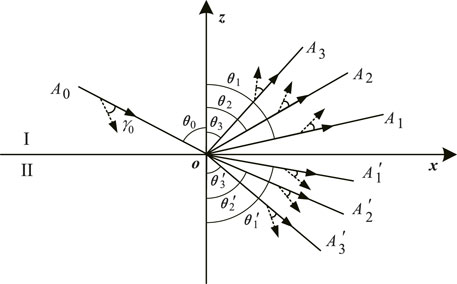
FIGURE 1. Reflection and transmission of plane waves at the interface separating two thermoelastic media. The solid and dashed arrows represent the propagation and attenuation directions, respectively.
Consider an incident P wave, where the superscripts i, r and t represent incident, reflected and transmitted, respectively. Then, the potential functions are
where
where Am and
where
where θ0 is the incidence angle and κ0 and α0 are given by Eq. 13 with k = k0 and γ = γ0 (see Figure 1). Generalized Snell’s law (Borcherdt, 2009, Eq. (5.2.20)) is
Because the phase velocities of the incident P (or T) and reflected P (or T) waves are the same, namely θ0 = θ1 (or θ0 = θ2), we get γ0 = γ1 (or γ0 = γ2) from Eqs. 12, 13. From Eqs 18 and Sharma (2018), we obtain
The reflection angle θ2 (or θ1) and transmission angles
and
where q0 is the vertical wavenumber of the incident wave, given by
where DR and DI denote the real and imaginary parts of the complex quantity D, pv denotes the principal value and the calculations of the vertical wavenumber are similar for the reflected (qm) and transmitted
where k0 and
where the subscripts 1 and 2 correspond to the transmitted P and T waves, respectively. Then, substituting Eq. 20 into (3)1, we obtain
where
On the other hand, for the incident S wave,
and, similarly,
the corresponding expressions are given in Eqs. 21, 32. From Eq. 25, the incident S wave is inhomogeneous, and so are the reflected and transmitted S waves. The properties of the reflected and transmitted longitudinal waves generated by an incident S wave are analogous to those of the incident P wave in Eqs. 26, 30.
At z = 0, the boundary conditions to be satisfied are the continuity of temperature, heat flux, and normal and tangential displacements and stresses (Ignaczak and Ostoja-Starzewski, 2010), i.e.,
Substituting Eqs. 2, 20 into the boundary conditions (35), we get the Knott equations (Knott, 1899) for the incident P wave
where
Similarly, we obtain the equations for the incident S wave, where A0 is its amplitude in Eq. 36, and
Using the relations between displacement amplitudes and their ratios, we obtain
where k0, km and
Let us consider the balance of energy flux between the incident wave and the reflected and transmitted waves at a surface element of unit area where the energy flux is the scalar product of the surface traction and particle velocity. The time-averaged energy flux is (Carcione, 2014, Eq. 3.106)
where
In the following expressions, we have omitted the subscripts z for simplicity. Denoting by
where
where the diagonal element a = b = 0 of this matrix corresponds to the energy flux of the incident wave, and a = b = 1, 2, 3 to the reflected P, T, and S waves, whereas the off-diagonal elements are the interference fluxes between the incident and reflected waves.
In the transmission medium, the energy flux can be express as
where
The diagonal elements are the energy fluxes of the transmitted P, T, and S waves. By scaling the energy flux with that of the incident wave
According to Eqs. 46 and 43 can be rewritten as
The energy-balance equation in the z-direction at the interface is (Carcione, 2014, Eq. 6.116; Wang E. et al., 2020)
where the sum of the vertical energy ratios result from the interaction between the incident wave and the three reflected waves, as well as interactions among the three reflected waves, is
Similarly, the corresponding vertical interference energy ratio for the transmitted waves is
Let us denote
The effects of thermoelasticity and the inhomogeneity angle are illustrated by considering the magnitudes, phase angles and energy of the reflection and transmission coefficients. We assume the following reference properties of the incidence and transmission media:Incidence medium: ρ = 2054 kg/m3, c = 960 kg/(m s2 K),
v0 and vS are the elastic longitudinal and transverse wave velocities, consistent with Eqs 114 and 19. The relaxation time is
(Rudgers, 1990), equal to 2.15 and 0.83 ns for the incidence and transmission media, respectively. The corresponding velocities and densities used here are those of Pilant (1979), whose scattering coefficients in the isothermal case are represented in his Figures 12-3 and 12-4, while the thermoelasticity properties are taken from Carcione et al. (2019).
Figures 2, 3 show the phase velocities and attenuation coefficients of the P and T waves in the incidence and transmission media, as a function of frequency, respectively. The solid, dashed and dotted solid lines correspond to inhomogeneity angles of 0°, 40° and 80°, and the superscripts LS and B represent the Lord-Shulman and classical-Biot theories, respectively. We can see that the low-frequency behavior is almost the same, the T wave is strongly dissipative at low frequencies (Figures 2D, 3D), and that the P wave has a relaxation peak (Figures 2B, 3B) caused by the thermal effects at a relaxation frequency of approximately
The LS model predicts a finite high-frequency limit velocity and a lower velocity dispersion of the T wave, which is wave-like at high frequencies. Both the P and T waves have abnormal velocity behaviors at and beyond the inflexion point in the B case (velocity decreases) and T waves have infinite speed at high frequencies (Figures 2C, 3C). The thermal relaxation hardly affects the wave propagation at relatively low frequencies. It can be seen that inflexion points in the P-wave velocity occur at a frequency of approximately 100 MHz.
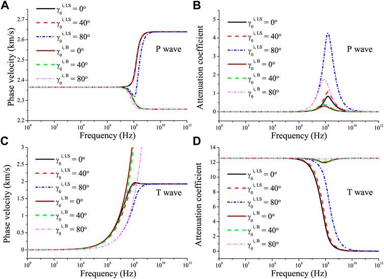
FIGURE 2. Phase velocity and attenuation coefficients of the P wave (A,B) and T wave (C,D) as a function of frequency in the incidence medium with different γ0. The superscripts LS and B represent the Lord-Shulman and classical-Biot theories, respectively.
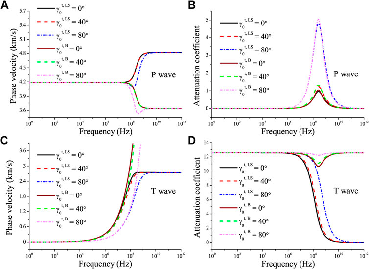
FIGURE 3. Phase velocity and attenuation coefficients of the P wave (A,B) and T wave (C,D) as a function of frequency in the transmission medium with different γ0. The superscripts LS and B represent the Lord-Shulman and classical-Biot theories, respectively.
Figures 4, 5 show the absolute values of the reflection and transmission coefficients and the corresponding phase angles as a function of the incidence angle in the case of an incident P wave with a frequency of 100 MHz. The elastic case is also indicated. If the two media are elastic, there is a critical angle at approximately 40°. If the incident wave travels along the z-direction (vertical), an incident P wave will generate reflected and transmitted longitudinal waves without conversion to the shear modes. The incident P wave is homogeneous when γ0 = 0°, and the behavior of the curves is close to that of the elastic case. We can see a pseudo critical angle at around 33° in the LS curves. Note that there is a converted S wave when the propagation angle is 0° and γ0 is non-zero as shown in Figures 4B,D, the effects on the magnitudes are relatively strong at the critical angle, and the phases of the reflected P wave are reversed at large incidence angles.
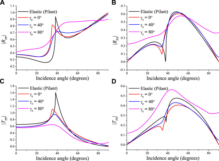
FIGURE 4. Absolute values of the reflected P (A), reflected S (B), transmitted P (C) and transmitted S (D) waves as a function of the P-wave incidence angle, corresponding to the elastic (black lines) and thermoelastic (color lines) cases at 100 MHz for different values of γ0.
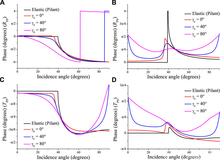
FIGURE 5. Same as Figure 4 but for the phase angles of the reflected P (A), reflected S (B), transmitted P (C) and transmitted S (D) waves.
The energy ratios are illustrated in Figure 6. Here, we plot the square root of the relative energy ratios to show the reflection and transmission, which is closer to the seismic response. The elastic phase and square root of the energy ratios are presented in Pilant (1979, Figure 12-3) and our results agree. The inhomogeneity angle affects the magnitudes of the reflected and transmitted waves (Figure 4) and consequently the energy partitions. In the elastic case, the energy flux perpendicular to the interface of the transmitted P wave (Figure 6C) vanish at the critical angle, because the wave propagates along the interface, carrying no energy flux in the vertical direction. The influence of γ0 on the reflected P wave (Figure 6A) is evident at the critical angle, while the effect on the other waves is maximum near grazing incidence. The sum of all the energy ratios is −1, which implies energy conservation at the interface as shown in Figure 7.
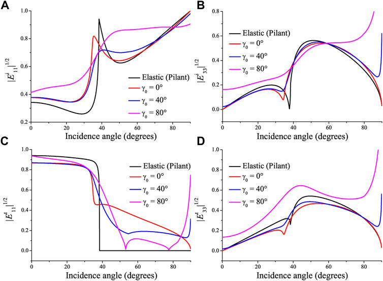
FIGURE 6. Same as Figure 4 but for the square root of the energy ratios of the reflected P (A), reflected S (B), transmitted P (C) and transmitted S (D) waves, considering the flux in the z-direction.
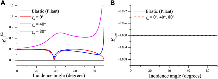
FIGURE 7. Square root of the interference energy (A) and the sum of the energy ratios (energy balance) (B) for an incident P wave (see Figure 4).
Next, we consider an incident S wave. Figures 8, 9 show the absolute values of the reflection and transmission coefficients and phase angles as a function of the incidence angle, and Figure 10 the corresponding energy ratios. Because the S-wave wavenumber kS is real (see Eq. 19), the inhomogeneity angle has no effect (see Eq. 25) as can be seen in Figures 8–11 (the three curves overlap). The energy of the reflected and transmitted P waves, at approximately 35° and 20° in Figures 10A,C, vanishes in the elastic (lossless) case, where the wave propagates along the interface and, as for the P wave, the plane wave is evanescent. The curves in Figure 10 are identical to those of Pilant (1979, Figure 12-4). At the S-wave critical angle (38°), the energy ratio of the reflected S wave is 1 (Figure 10B), whereas the energy of other waves is zero, since the wave propagating along the interface carries no energy vertically. In the LS case, the behavior is analogous to the elastic case. However, there is transmission for all incidence angles and non-zero interference energy. Moreover, significant energy conversion occurs, as shown in Figure 11A, i.e., the LS model predicts more interference energy than the elastic one. The energy conservation at the interface is satisfied, as can be seen in Figure 11B. The same results have been illustrated at the free surface of double-porosity and two double-porosity media (Sharma, 2013; Wang E. et al., 2020).
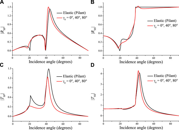
FIGURE 8. Absolute values of the reflected P (A), reflected S (B), transmitted P (C) and transmitted S (D) waves as a function of the S-wave incidence angle, corresponding to the elastic (black lines) and thermoelastic (red line) cases at 100 MHz for different values of γ0.
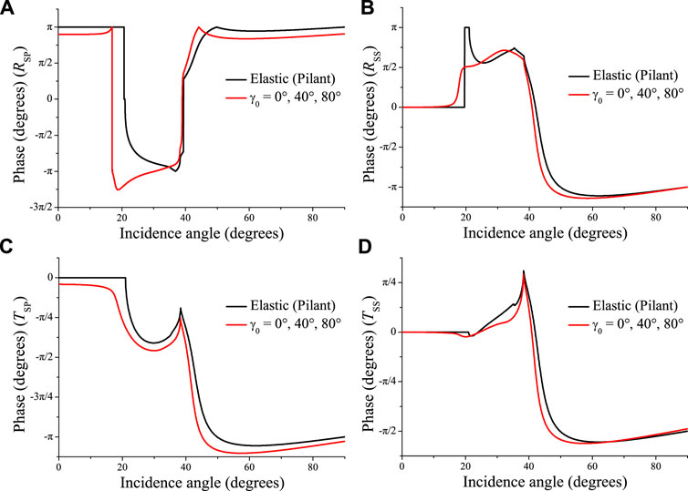
FIGURE 9. Same as Figure 8 but for the phase angles of the reflected P (A), reflected S (B), transmitted P (C) and transmitted S (D) waves.
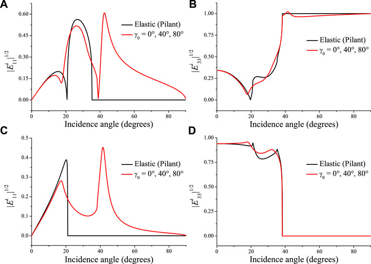
FIGURE 10. Same as Figure 8 but for the square root of the energy ratios of the reflected P (A), reflected S (B), transmitted P (C) and transmitted S (D) waves, considering the flux in the z-direction.
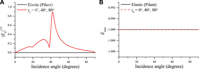
FIGURE 11. Square root of the interference energy (A) and the sum of the energy ratios (B) (see Figure 8).
Next, we study the effect of the relaxation time (see Eqs. 52, 53. Increasing
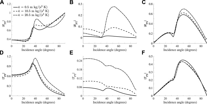
FIGURE 12. Absolute values of the reflected P (A), reflected T (B), reflected S (C), transmitted P (D), transmitted T (E) and transmitted S (F) waves as a function of the P-wave incidence angle at 100 MHz and γ0 = 40°, where we vary the thermal conductivity of the incidence media.
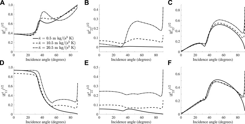
FIGURE 13. Same as Figure 12 but for the square root of the energy ratios of the reflected P (A), reflected T (B), reflected S (C), transmitted P (D), transmitted T (E) and transmitted S (F) waves, considering the flux in the z-direction.
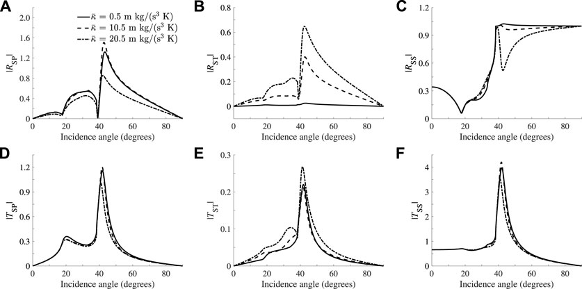
FIGURE 14. Same as Figure 12 but for the absolute values of the reflected P (A), reflected T (B), reflected S (C), transmitted P (D), transmitted T (E) and transmitted S (F) waves as a function of the S-wave incidence angle.
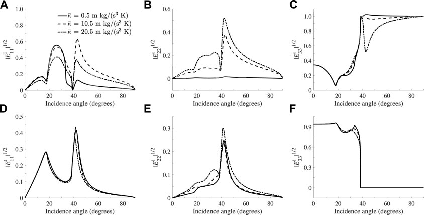
FIGURE 15. Same as Figure 14 but for the square root of the energy ratios of the reflected P (A), reflected T (B), reflected S (C), transmitted P (D), transmitted T (E) and transmitted S (F) waves, considering the flux in the z-direction.
We obtain the reflection and transmission coefficients at an interface separating two thermoelastic media, whose properties are based on the Lord-Shulman theory. Comparing these coefficients with those of the elastic (lossless) case, shows that critical angles, amplitudes and energy ratios, including interference fields, are affected by the presence of the thermal wave. Since the presence of this wave makes the media anelastic, the propagation and attenuation vectors of the incident wave do not necessarily coincide (inhomogeneous plane wave). The effect of the inhomogeneity angle is more noticeable at the critical angle and near grazing incidence angle for an incident P wave, and has no effect for an incident S wave, since the wavenumber of this wave is real. Then, we analyze the influence of the thermal conductivity (relaxation time) of the incidence media, which shows that this property affects the converted thermal wave more than the others, as expected. The calculations have been verified with the conservation of energy. This study is aimed to further improve the understanding of the behavior of the internal structure of the Earth, where the temperature effects are important.
The raw data supporting the conclusion of this article will be made available by the authors, without undue reservation.
WH, L-YF, and JC contributed to conception and design of the study. WH wrote the first draft of the manuscript. WH, L-YF, JC, and TH wrote sections of the manuscript. All authors contributed to manuscript revision, read, and approved the submitted version.
The research is supported by the National Natural Science Foundation of China (Grant No. 41821002), 111 project “Deep-Superdeep Oil & Gas Geophysical Exploration” (B18055) and Innovation fund project for graduate students of China University of Petroleum (East China) (No. CXJJ-2022-17).
The authors declare that the research was conducted in the absence of any commercial or financial relationships that could be construed as a potential conflict of interest.
All claims expressed in this article are solely those of the authors and do not necessarily represent those of their affiliated organizations, or those of the publisher, the editors and the reviewers. Any product that may be evaluated in this article, or claim that may be made by its manufacturer, is not guaranteed or endorsed by the publisher.
The Supplementary Material for this article can be found online at: https://www.frontiersin.org/articles/10.3389/feart.2022.850331/full#supplementary-material
Ackerman, C. C., Bertman, B., Fairbank, H. A., and Guyer, R. A. (1966). Second Sound in Solid Helium. Phys. Rev. Lett. 16 (18), 789–791. doi:10.1103/physrevlett.16.789
Armstrong, B. H. (1984). Models for Thermoelastic Attenuation of Waves in Heterogeneous Solids. Geophysics 49 (7), 1032–1040. doi:10.1190/1.1441718
Biot, M. A. (1956). Thermoelasticity and Irreversible Thermodynamics. J. Appl. Phys. 27 (3), 240–253. doi:10.1063/1.1722351
Buijze, L., van Bijsterveldt, L., Cremer, H., Paap, B., Veldkamp, H., Wassing, B. B. T., et al. (2019). Review of Induced Seismicity in Geothermal Systems Worldwide and Implications for Geothermal Systems in the Netherlands. Neth. J. Geosciences 98, 1–27. doi:10.1017/njg.2019.6
Carcione, J. M. (2014). Wave fields in Real media. Theory and Numerical Simulation of Wave Propagation in Anisotropic, Anelastic and Porous media. 3rd ed. Elsevier.
Carcione, J. M., Wang, Z.-W., Ling, W., Salusti, E., Ba, J., and Fu, L.-Y. (2019). Simulation of Wave Propagation in Linear Thermoelastic media. Geophysics 84 (1), T1–T11. doi:10.1190/geo2018-0448.1
Cattaneo, C. (1958). Sur une forme de l’équation de la chaleur éliminant paradoxe d’une propagation instantantée. Comptes rendus de l’Académie des Sci. 247, 431–433.
Chadwick, P. (1960). Thermoelasticity. The Dynamical Theory. Prog. Solid Mech. 1, 263–328. doi:10.1136/bmj.1.5165.56
Denneman, A. I. M., Drijkoningen, G. G., Smeulders, D. M. J., and Wapenaar, K. (2002). Reflection and Transmission of Waves at a Fluid/porous‐medium Interface. Geophysics 67 (1), 282–291. doi:10.1190/1.1451800
Deresiewicz, H. (1957). Plane Waves in a Thermoelastic Solid. The J. Acoust. Soc. America 29 (2), 204–209. doi:10.1121/1.1908832
Green, A. E., and Lindsay, K. A. (1972). Thermoelasticity. J. Elasticity 2 (1), 1–7. doi:10.1007/bf00045689
Hobiny, A. D., and Abbas, I. A. (2020). Fractional Order Thermoelastic Wave Assessment in a Two-Dimension Medium with Voids. Geomechanics Eng. 21 (1), 85–93.
Ignaczak, J., and Ostoja-Starzewski, M. (2010). Thermoelasticity with Finite Wave Speeds. Oxford, United Kingdom: Oxford University Press.
Jackson, H. E., Walker, C. T., and McNelly, T. F. (1970). Second Sound in NaF. Phys. Rev. Lett. 25 (1), 26–28. doi:10.1103/physrevlett.25.26
Jiao, F., Wei, P., Zhou, X., and Zhou, Y. (2019). The Dispersion and Attenuation of the Multi-Physical fields Coupled Waves in a Piezoelectric Semiconductor. Ultrasonics 92, 68–78. doi:10.1016/j.ultras.2018.09.009
Knott, C. G. (1899). III. Reflexion and Refraction of Elastic Waves, with Seismological Applications. Lond. Edinb. Dublin Philosophical Mag. J. Sci. 48, 64–97. doi:10.1080/14786449908621305
Kumar, R., and Sarthi, P. (2006). Reflection and Refraction of Thermoelastic Plane Waves at an Interface between Two Thermoelastic media without Energy Dissipation. Arch. Mech. 58 (2), 155–185.
Kumar, R., Gupta, V., and Abbas, I. A. (2013). Plane Deformation Due to thermal Source in Fractional Order Thermoelastic media. Jnl Comp. Theo Nano 10 (10), 2520–2525. doi:10.1166/jctn.2013.3241
Lord, H. W., and Shulman, Y. (1967). A Generalized Dynamical Theory of Thermoelasticity. J. Mech. Phys. Sol. 15 (5), 299–309. doi:10.1016/0022-5096(67)90024-5
Maxwell, J. C. (1867). On the Dynamical Theory of Gases. Philosophical Trans. R. Soc. Lond. 157, 49–88.
McNelly, T. F., Rogers, S. J., Channin, D. J., Rollefson, R. J., Goubau, W. M., Schmidt, G. E., et al. (1970). Heat Pulses in NaF: Onset of Second Sound. Phys. Rev. Lett. 24 (3), 100–102. doi:10.1103/physrevlett.24.100
Rokhlin, S. I., Bolland, T. K., and Adler, L. (1986). Reflection and Refraction of Elastic Waves on a Plane Interface between Two Generally Anisotropic media. J. Acoust. Soc. America 79 (4), 906–918. doi:10.1121/1.393764
Rudgers, A. J. (1990). Analysis of Thermoacoustic Wave Propagation in Elastic media. J. Acoust. Soc. America 88 (2), 1078–1094. doi:10.1121/1.399856
Sarkar, N., and Mondal, S. (2020). Thermoelastic Plane Waves under the Modified green–lindsay Model with Two-Temperature Formulation. J. Appl. Mathematics Mech./Z. für Angew. Mathematik Mechanik 100 (11), 1–17. doi:10.1002/zamm.201900267
Sarkar, N., Abo-Dahab, S. M., and Mondal, S. (2020). Reflection of Magneto-Thermoelastic Waves at a Solid Half-Space under Modified Green-Lindsay Model with Two Temperatures. J. Therm. Stresses 43 (9), 1083–1099. doi:10.1080/01495739.2020.1768991
Savage, J. C. (1966). Thermoelastic Attenuation of Elastic Waves by Cracks. J. Geophys. Res. 71 (16), 3929–3938. doi:10.1029/jz071i016p03929
Sharma, J. N., Kumar, V., and Chand, D. (2003). Reflection of Generalized Thermoelastic Waves from the Boundary of a Half-Space. J. Therm. Stresses 26 (10), 925–942. doi:10.1080/01495730306342
Sharma, M. D. (2013). Effect of Local Fluid Flow on Reflection of Plane Elastic Waves at the Boundary of a Double-Porosity Medium. Adv. Water Resour. 61, 62–73. doi:10.1016/j.advwatres.2013.09.001
Sharma, M. D. (2018). Reflection-refraction of Attenuated Waves at the Interface between a Thermo-Poroelastic Medium and a Thermoelastic Medium. Waves in Random and Complex Media 28 (3), 570–587. doi:10.1080/17455030.2017.1370154
Singh, M. C., and Chakraborty, N. (2013). Reflection and Refraction of P-, SV- and thermal Wave, at an Initially Stressed Solid–Liquid Interface in Generalized Thermoelasticity. Appl. Math. Model. 37 (1-2), 463–475. doi:10.1016/j.apm.2012.03.008
Sinha, S. B., and Elsibai, K. A. (1997). Reflection and Refraction of Thermoelastic Waves at an Interface of Two Semi-infinite media with Two Relaxation Times. J. Therm. Stresses 20 (2), 129–145. doi:10.1080/01495739708956095
Sinha, S. B., and Elsibai, K. A. (1996). Reflection of Thermoelastic Waves at a Solid Half-Space with Two Relaxation Times. J. Therm. Stresses 19 (8), 749–762. doi:10.1080/01495739608946205
Veres, I. A., Berer, T., and Burgholzer, P. (2013). Numerical Modeling of Thermoelastic Generation of Ultrasound by Laser Irradiation in the Coupled Thermoelasticity. Ultrasonics 53 (1), 141–149. doi:10.1016/j.ultras.2012.05.001
Vernotte, P. (1948). Théorie continue et théorie moléculaire des phénomènes thermocinétiques. Comptes rendus de l’Académie des Sci. 227, 43–44.
Wang, B. L., and Li, J. E. (2013). Hyperbolic Heat Conduction and Associated Transient thermal Fracture for a Piezoelectric Material Layer. Int. J. Sol. Structures 50 (9), 1415–1424. doi:10.1016/j.ijsolstr.2013.01.013
Wang, E., Carcione, J. M., Yuan, Y., and Ba, J. (2021). Reflection of Inhomogeneous Plane Waves at the Surface of a Thermo-Poroelastic Medium. Geophys. J. Int. 224 (3), 1621–1639.
Wang, E., Carcione, J. M., Ba, J., and Liu, Y. (2020a). Reflection and Transmission of Plane Elastic Waves at an Interface between Two Double-Porosity media: Effect of Local Fluid Flow. Surv. Geophys. 41 (2), 283–322. doi:10.1007/s10712-019-09572-6
Wang, Z.-W., Fu, L.-Y., Wei, J., Hou, W., Ba, J., and Carcione, J. M. (2020b). On the Green Function of the Lord-Shulman Thermoelasticity Equations. Geophys. J. Int. 220 (1), 393–403. doi:10.1093/gji/ggz453
Wei, W., Zheng, R., Liu, G., and Tao, H. (2016). Reflection and Refraction of P Wave at the Interface between Thermoelastic and Porous Thermoelastic Medium. Transp Porous Med. 113 (1), 1–27. doi:10.1007/s11242-016-0659-1
Zener, C. (1938). Internal Friction in Solids II. General Theory of Thermoelastic Internal Friction. Phys. Rev. 53 (1), 90–99. doi:10.1103/physrev.53.90
Zenkour, A. M., Mashat, D. S., and Abouelregal, A. E. (2013). The Effect of Dual-Phase-Lag Model on Reflection of Thermoelastic Waves in a Solid Half Space with Variable Material Properties. Acta Mechanica Solida Sinica 26 (6), 659–670. doi:10.1016/s0894-9166(14)60009-4
The strain (ϵ)-displacement (u) and constitutive relations (Biot, 1956) are
and
respectively, where ϵ = ϵii, σij are the stress components, δij are the Kronecker components and fij are external stress forces, and the Einstein summation is asssumed.
The components of the equation of momentum conservation are
where fi are the components of external body forces. Substituting the constitutive relations (A.2) into Eq. A.3 and using (A.1), in the absence of external body and stress forces, we obtain
On the other hand, the law of heat conduction is
where T is the tempeature field and q a heat source.
Keywords: thermoelasticity and elasticity, reflection and transmission coefficients, energy partitions, inhomogeneous plane waves, attenuation angle
Citation: Hou W, Fu L-Y, Carcione JM and Han T (2022) Reflection and Transmission of Inhomogeneous Plane Waves in Thermoelastic Media. Front. Earth Sci. 10:850331. doi: 10.3389/feart.2022.850331
Received: 07 January 2022; Accepted: 29 March 2022;
Published: 26 April 2022.
Edited by:
Jonas D. De Basabe, Center for Scientific Research and Higher Education in Ensenada (CICESE), MexicoCopyright © 2022 Hou, Fu, Carcione and Han. This is an open-access article distributed under the terms of the Creative Commons Attribution License (CC BY). The use, distribution or reproduction in other forums is permitted, provided the original author(s) and the copyright owner(s) are credited and that the original publication in this journal is cited, in accordance with accepted academic practice. No use, distribution or reproduction is permitted which does not comply with these terms.
*Correspondence: Li-Yun Fu, bGZ1QHVwYy5lZHUuY24=; José M. Carcione, am9zZS5jYXJjaW9uZUBnbWFpbC5jb20=
Disclaimer: All claims expressed in this article are solely those of the authors and do not necessarily represent those of their affiliated organizations, or those of the publisher, the editors and the reviewers. Any product that may be evaluated in this article or claim that may be made by its manufacturer is not guaranteed or endorsed by the publisher.
Research integrity at Frontiers
Learn more about the work of our research integrity team to safeguard the quality of each article we publish.