 Yuan Mei
 Dong-bo Zhou
 Chang-ming Hu1,2
 Xue-yan Wang
 Yuhang Zhang
 Nan Xiao
 Wenyan Shi
- 1School of Civil Engineering, Xi’an University of Architecture and Technology, Xi’an, China
- 2Shaanxi Key Lab of Geotechnical and Underground Space Engineering, Xi’an, China
- 3School of Urban Planning and Municipal Engineering, Xi’an Polytechnic University, Xi’an, China
Taking the loess high-fill project of Lv Liang airport in China as the research object, large-scale centrifugal tests were carried out to investigate the deformation characteristics of the collapsible loess ultrahigh-fill slope under natural moisture content and saturated state by using a joint model of undisturbed loess and remolded loess. The results show that the consolidation deformation of the collapsible loess ultrahigh-fill slope is the main factor causing its deformation. The post-construction deformation amount and deformation rate are large in the early stage, and the relationship between the post-construction deformation and thickness of filling body is linear. When the water content of soil increases due to infiltration, the consolidation of the filling body and the collapse of the undisturbed foundation loess will cause settlement and deformation of the slope. The slope may crack along the soft zone formed when the water infiltrates. When failure occurs, the sliding surface will pass through the collapsible soil layer. The contact surface between the collapsible loess layer and the adjacent soil layer is part of the sliding surface, and the contact surface with a relatively low strength will be damaged first. When the strength difference between adjacent soil layers is large, the upper soil layer on the slip surface shows a typical translational sliding mode. The slip surface is approximately arc-shaped, and there is a transition layer with a specific thickness between the slip surface and contact surface. The water content of the high-fill slope has a great influence on the post-construction settlement of the slope crest and slope stability. The post-construction settlement of the slope crest increases with the increase in the water content of the filling body, and the stability coefficient of the slope decreases with the increase in the water content of the filling body. In the saturated state, the sliding force of soil increases, the shear strength decreases, and the stability of high fill slope decreases. Therefore, it is necessary to strengthen the inspection of the rationality of drainage system design in slope construction to ensure slope safety.
1 Introduction
To solve the contradiction between land supply and infrastructure construction, scientific researchers have increased the research on bad rock and soil mass (Fan et al., 2019; Liu et al., 2020a; Wang et al., 2021a; Wang et al., 2021b; Wang et al., 2022a). a large number of high-fill slopes have emerged in large-scale projects in collapsible loess regions of the world, typified by Western China. The stability of collapsible loess ultrahigh-fill slopes has attracted increasing attention from engineers and has become an important issue that needs to be studied urgently.
In the field of geotechnical engineering, to provide the same self weight stress level as the prototype, a physical model of scale is usually built in a large centrifuge (Schofield, 1980; Taylor, 1995; Shen et al., 2021). The centrifugal model can be used to extrapolate the results of the scale model to the full-scale prototype (Charles, 2014). It provides physical data for the study of deformation and failure mechanism, as well as for the verification and numerical analyses (Caicedo and Thorel, 2014). In recent years, the use of centrifugal model tests to study the slope deformation characteristics under different conditions has gradually emerged, and some important results have been obtained. Some scholars have studied the deformation characteristics of slopes in different regions and soils. Cheng et al. studied the influence of loess cracks on slope stability through geotechnical centrifugal test (Cheng et al., 2021). Based on the high-fill engineering of the Yan’an loess gully, Wu et al. studied the deformation characteristics and stability of the high-fill slope with the change in water level through centrifugal model tests and finite element stress analysis (Wu et al., 2017). Miao et al. then analyzed the stability and failure mode of slopes in the Three Gorges Reservoir area by centrifugal model tests and finite element simulation (Miao et al., 2018). Peng et al. analyzed and compared the deformation characteristics and failure mechanism of homogeneous loess slopes and a double paleosol-interlayer loess slope under different excavation slope angles based on centrifugal model tests. Then some scholars used centrifugal model tests to analyze the effect of rainfall on slope deformation characteristics (Peng et al., 2019). Ling et al. studied the mechanical behavior of soil under triaxial and plane strain conditions through a centrifugal model test and simulated the influence of rainfall on slope stability, which verified the importance of centrifugal model tests in slope instability research (Ling et al., 2009). Zhang et al. took the Jiaojia No. 13 landslide in Heifangtai area as the geological prototype and carried out a series of centrifugal tests to study the deformation and failure characteristics of the slope caused by a continuous rise in groundwater level. At the same time, centrifugal tests on the seismic performance of slopes have gradually emerged (Zhang et al., 2019). Enomoto et al. conducted A series of dynamic centrifuge model tests in order to evaluate some factors affecting the seismic performance of hillside embankments consisting of sandy or silty soils and resting on stiff base slope. The effects of seepage water elevation in embankments, toe drain, embankment height, base slope inclination, soil compaction, and fill materials on the seismic behaviour of embankments were investigated (Enomoto and Sasaki, 2015). Yan et al. used a dynamic centrifugal model to study the seismic performance and dynamic deformation characteristics of a pile group foundation with an inclined weak interlayer slope (Yan et al., 2020). Zhang and Wang (2017) studied the three-dimensional failure behavior of reinforced slopes through a series of centrifugal model tests and summarized four main failure modes of reinforced slopes. Based on the equivalent model, a slice method was proposed to analyze the stability level of reinforced slopes (Zhang and Wang, 2017). Park et al. mixed a small amount of Portland cement into different plastic clays for centrifugal tests, studied the static and dynamic failure mechanisms of sensitive clay slopes, and explained the experimental results in conjunction with the existing literature to further understand the controlling factors of clay instability caused by dynamic load (Park and Kutter, 2015). Li et al. reproduced the sliding instability process of the pre-reinforced high-fill slope at Panzhihua Airport through large-scale centrifugal model tests, obtained the characteristic parameters of slope deformation and rupture, and clarified the mechanism of slope instability (Li et al., 2013). Yang et al. conducted a series of dynamic centrifugal tests to study the influence of the angle of sand compaction pile (SCP) improvement zone on mitigating the liquefaction-induced settlement of embankment crests (Li et al., 2021a). Jing et al. studied the deformation behavior of high rockfill embankment during construction and operation through centrifugal model test (Jing et al., 2021). Luo et al. studied the law of sand slope stability with slope gradient and water content based on the geotechnical centrifugal model test technology, analyzed the deformation characteristics and failure mode of sand slope under a centrifugal load, and discussed the comparison mechanism of the influence of water migration phenomenon of sand with a higher water content on slope stability (Luo et al., 2018). Chen et al. revealed the deformation characteristics and the change characteristics of slope stress in the process of excavation and unloading through centrifugal model tests and analyzed the influence of the change in soil parameters (compactness and water content) on the deformation characteristics of the slope (Chen and Tang, 2008). The above research on the characteristics of slope deformation is less for high-fill slopes (Li et al., 2013; Wu et al., 2017; Cheng et al., 2021), especially for the deformation law of collapsible loess slope. Moreover, most of the same type of tests are carried out by using remolded loess instead of undisturbed loess to make models. Even though a few tests use undisturbed loess to make models, due to the small size of the models, the boundary conditions will have a great impact on the test results (Drnevich et al., 1989). The method of making large-scale undisturbed soil and geotechnical test models and the key technologies of the test have no matured experience to draw on.
This study took the loess high-fill slope project of Lvliang airport (as shown in Figure 1) as the research object. Undisturbed loess and remolded loess were used to make the model, and large-scale centrifugal tests were carried out to study the deformation characteristics of the collapsible loess ultrahigh-fill slope in natural moisture content and saturation state. The research results can provide a reliable basis for the design and construction of similar projects.
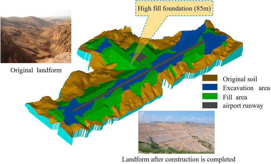
FIGURE 1. Project profile of test section in Lvliang airport.
2 Test Plan
The LXJ-4-450 geotechnical centrifuge model test machine of China Institute of Resources and Hydropower Research was used in the experiments. The effective radius of the centrifuge is 5.03 m, the maximum acceleration is 300 g, the effective load is 1.5 t, and the effective load capacity is 450 g t. The data acquisition equipment uses laser displacement sensors and matching acquisition and camera systems. The centrifuge used for the tests is shown in Figure 2.
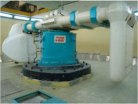
FIGURE 2. Centrifuge used in the tests.
2.1 Principle and Similarity of Centrifugal Model Test
In the centrifugal model test, when considering the geotechnical problems related to the model’s own gravity, the strain energy of the centrifugal test model and the prototype at the corresponding points can maintain good similarity (Hu et al., 2012a). The model and prototype similarity rates involved in the test are listed in Table 1.
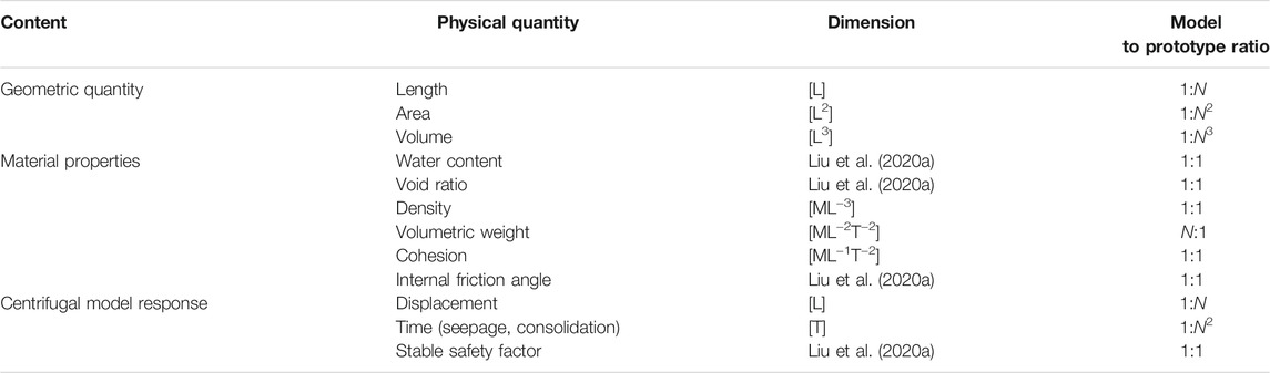
TABLE 1. Scaling velocity of centrifugal model test.
2.2 Model Design
Because the airport runway is built on a loess ridge, a large number of high-fill slopes emerged, and the differences between the slopes vary greatly due to the original terrain. In the selection process of the model section, the slope ratio, slope height of filling body, and the influence of foundation soil properties on the slope were mainly considered. To make the test results reflect more slope conditions as much as possible, the most representative sections were selected. The original plan was to carry out two groups of different slope tests to include more slopes in the tests. However, due to the limited fund, time, and equipment, the section with the lowest safety factor was finally selected as the object of the tests. Based on the preliminary design scheme and calculation results of Lvliang airport, a typical section is shown in Figure 3.
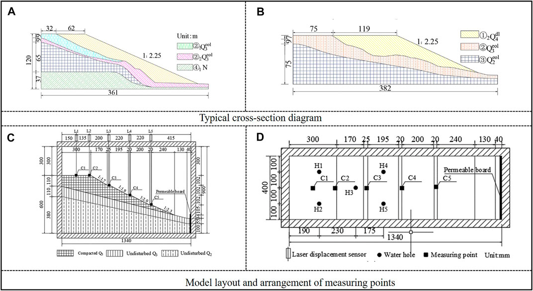
FIGURE 3. (A) Typical cross-section A, (B) Typical cross-section B; (C) plan, and (D) elevation.
According to the above section form and soil distribution, combined with the comprehensive consideration of the size of the test model box and the geometric size of the prototype, the similarity ratio of the test model was set as n = 180. The model soil layer was divided into three layers from the top to the bottom: Q3 Malan loess, which was compacted in the top layer, with a compactness of 93%; Q3 Malan loess, which was undisturbed in the middle layer, with loose structure, large pores, low toughness, and dry strength, with medium collapsibility; Q2 Lishi loess, which was undisturbed in the bottom layer, with hard plasticity, medium toughness, and dry strength. The main physical properties and shear strength indicators of each soil layer in the model are presented in Table 2.
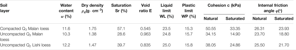
TABLE 2. Physical and mechanical incides of model soil.
The model size was 1,340 mm (length) × 400 mm (width) × 600 mm (height). There were four berms on the filling body. The slope was divided into four sections, the slope ratio from the top to the bottom is: 1:1.7, 1:1.9, 1:2, and 1:2.3, with a comprehensive slope ratio of 1:2.1. The model design and measurement point arrangement are depicted in Figures 3C,D.
2.3 Model Making
2.3.1 Making of Undisturbed Soil
The undisturbed soil samples of the model were obtained from a typical section of Lvliang Mountain, Shanxi and sealed and transported to the laboratory (Hu et al., 2012b; Hu et al., 2012c). After the soil samples were obtained onsite and transported to the laboratory, the process of laying out, cutting, and combining the samples according to the design size of the model is presented in Figure 4A.
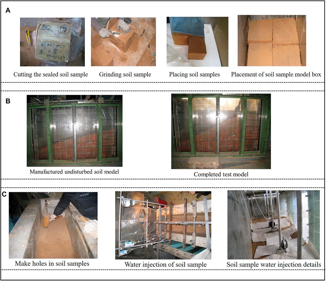
FIGURE 4. (A) Model making; (B) Completed test model, (C) Soil sample opening for water injection.
To reduce the friction of the inner wall of the model box, transparent liquid silicone grease was applied to the inner wall and it was then covered with a plastic film to eliminate the boundary effect on the test results as much as possible (refer to Figure 4). The gap between the undisturbed soil samples was filled with quicklime, water, and loess soil mixture, where the thickness of the mixture did not exceed 5 mm. Furthermore, to maximize the restoration of stress and consolidation of the undisturbed soil, reduce the experimental errors caused by the weak joints, and prevent the soil samples from being broken due to uneven contact surfaces during loading, after the original undisturbed soil layer in the model was completed, a plastic film was used to cover the upper surface, and the plastic film was covered with loose Q3 Malan loess (layered and lightly compacted), and the compaction degree was controlled to approximately 85%. Based on the thickness of the overlying soil before sampling the original soil sample, the thickness of the overlying soil on the model was calculated to be approximately 20 cm according to the model similarity ratio.
After completion, the model was loaded on the centrifuge until the acceleration was 180 g. Then, the plastic film of the model was removed and the Q3 Malan loess was covered and compacted. After the upper overburden of the undisturbed soil layer was cleaned, the undisturbed soil layer was treated thoroughly to meet the requirements of the design size of the model. When the size error of each part was not more than 5 mm, the filling body of the model was made.
2.3.2 Making of Filling Body
The soil used for compacted the Malan loess filling body in the model was crushed by the disturbed Malan loess obtained from the field and then screened by a fine sieve with a diameter of 2 mm. The layer was compacted on the original soil layer of the model, where the compaction degree was controlled to 93%. When each part of the filling body reached the design size of the model, a geotechnical knife was used to trim the design, where the size error did not exceed 5 mm.
The model designed according to the above manufacturing method and measurement system is shown in Figure 4B.
2.4 Test and Measurement System
Considering the possible deformation of the slope body, the test needs to measure the vertical deformation of the slope crest and the berm at all levels and the internal deformation of the model. Limited by the test conditions, only five laser displacement sensors (C1 to C5) were set along the longitudinal centerline of the model box (Wang et al., 2020; Li et al., 2021b; Wang et al., 2022b).
The laser displacement sensor was placed 20 cm away from the boundary of the model box (which was outside the range of boundary influence) to minimize the influence of the side of the model box on the test results (Mei et al., 2015). The laser aiming positions were respectively the model deformation measuring points 1–5. The measuring points 1 and 2 displacement slope top and the measuring points 3, 4, and 5 are respectively located at each level of the berm on the slope.
Additionally, due to the limitation of the test method, it was difficult to perform a real-time dynamic measurement of the internal deformation trend of the model, and the internal deformation of the test model can only be measured at the end of the test.
In this test, the model was marked with pushpins with a reflective paper. The vedrtical and horizontal spacing was approximately 3 cm × 3 cm. A vertical and horizontal grid was set on the outer wall of the model box with a grid size of 10 cm × 10 cm. After the test, the relative displacements of the intersections of the markers with the grid lines on the glass plate of the model box were measured respectively, and the approximate trend of the internal displacement of the model was obtained.
2.5 Test Conditions
2.5.1 Working Condition 1: High Slope Stability Test With Natural Moisture Content
After the model was made, it was loaded in a centrifuge, and the centrifugal acceleration was increased by 20 g per stage to 180 g. During the loading process, each time the acceleration of the former stage was increased, the acceleration was maintained, and the operation was continued for 5 min to make the model deformation basically stable. According to the calculation, when the laser displacement sensor used in the test was under the acceleration of 180 g, the measurement error caused by the vibration of its instrument frame was not greater than ±0.2 mm (real-time data can be used for measurement during the test). Therefore, during the test, under each acceleration level, the centrifuge continued to run with constant acceleration. If the fluctuation range of the laser displacement sensor is less than ±0.2 mm, the model is considered to be stable in deformation, but it needs to be loaded for 5 min stably. If the model does not reach this standard within a certain level of acceleration within 5 min, the acceleration is maintained and the operation is continued until the requirements are met. After accelerating to 180 g according to the above loading system, we maintained the acceleration until the model deformation was stable, and then we unload in stages. During the unloading process, the acceleration decreased by 40 g per stage, and the final stage was 20 g until the machine was shut down. During the unloading process, when the acceleration was reduced, we maintained the acceleration and continued to run for 2 min. When the acceleration was reduced to zero, we continued to observe until the deformation of the model was stable.
2.5.2 Working Condition 2: High Slope Stability Test Under Saturated Conditions
In the actual project, due to poor drainage conditions, vertical caves are often formed in high-fill slopes (Jiang et al., 2016; Fan et al., 2020; Kang et al., 2020). A large amount of water enters the interior of high slopes through the caves, which saturates the slope soil and poses a great threat to the stability of such slopes. The centrifuge cannot immerse the model in the loading process. Therefore, after completing test condition 1, we stopped and removed the model sensor. Then, we drilled 5 immersion holes with a diameter of 5 mm at different positions of the model. The depth of the hole to the contact surface between the top filling body and the undisturbed Malan Loess in the middle layer, as shown in Figure 3D.
A medical infusion device was used to continuously inject water into the model, so that the average saturation of the model reached more than 75%. At this time, the saturation of the top filling body and the undisturbed Malan loess in the middle layer was estimated to be over 80% (The water content in the cave is large and the other parts are relatively small, which cannot be measured in real time due to the test conditions). It was estimated that 30 kg of water was needed for the test. The soil sample openings for water injection are shown in Figure 4C.
It should be noted that the purpose of the test in working condition 2 is to analyze the deformation law of the model in the saturated state of the top filling body and the middle layer of the original Malan loess. Although the submerged caves are unevenly distributed and anisotropic in the actual project (Liu et al., 2020b; Yuan et al., 2021; Yuan et al., 2022; Zhou et al., 2022), in the process of model making, it is impossible to make caves according to the actual shape of the cave. In addition, water immersion in the cave in the experimental model is only a simulation of the immersion path of the prototype, and it is not necessary to make the cave according to its actual shape. Therefore, according to the general principle that the simpler the centrifugal model, the more obvious the regularity of the test results, the test did not consider the heterogeneity and anisotropy of the cave. During the model water injection process, five groups of dial gauges were set at the position of the laser displacement sensor to measure the vertical deformation of the model during immersion. To prevent the model from softening after immersion in water, the dial gauges pierced the model. A 2 cm × 2 cm plexiglass sheet was placed. Moreover, to prevent water from overflowing from the water immersion holes and causing erosion and damage to the sloping surface when the water is soaked too fast, the surface of the sloping surface was covered with an absorbent cotton cloth to absorb the overflowing water during the immersion process. After completing the water immersion, the Q3 fine soil was used to fill the water immersion holes, and then the test was carried out according to the loading and unloading schemes of working condition 1. After the test, the model box was emptied. During the emptying process, the model was sampled to determine the moisture content.
2.5.3 Working Condition 3: Measurement of Model Box Deformation
After the model box was emptied, we installed the instrument and the instrument frame again. Then, we extended the No. 1 to 5 displacement sensor rods and aimed at the bottom of the model box. We put a steel block of the same quality as the model in the model box and placed the model box in the centrifuge. The machine was loaded to 180 g, and the deformations of the model box and the instrument frame during the loading and unloading processes were recorded. These were used to correct the data measured in working conditions 1 and 2.
3 Test Results and Analysis
The test results obtained include the following: vector diagram of the lateral deformation of the model before and after each test, deformation curve of each measuring point during the test, deformation curve of the position of each measuring point during the model immersion, moisture content of each part of the model after the test, deformation curve of the model box and the instrument frame at each level of acceleration, and crack development of the model during the test.
The preliminary analysis test results show that the moisture content of the model meets the test requirements of working condition 2 after immersion in water. The model reaches the stability standard within 5 min at each level of acceleration, and the test achieves the expected results.
3.1 Stability Analysis
According to the law of model similarity, when all the dimensionless independent variables of the model and the prototype have a one-to-one correspondence, the model and the prototype are completely similar. When the soil slope is stable, the slope deformation and the centrifugal acceleration are approximately linear; however, when the soil slope is unstable, the relationship between the slope deformation and the centrifugal acceleration will change, and even a small acceleration increase will cause a large lateral displacement and corresponding deformation. Therefore, the slope stability can be analyzed by using the trend of the relationship between the relative deformation Δδ (the ratio of the deformation value Si of the model measurement point position at a certain acceleration level to the thickness of the soil layer at the corresponding position of the measurement point is called relative deformation: (Δδ = Si/hi) of the model measurement point and the acceleration (a) curve.
Because the undisturbed soil of the model is pre-compressed, the deformation of the model under the condition of natural moisture content should mainly come from the top compacted Malan loess layer. However, under the condition of saturation, the strength of the top compacted Malan loess layer and the middle undisturbed Malan loess layer will be greatly reduced, and the deformation mainly comes from both. Therefore, the thickness of the deformed soil layer under the condition of natural water content is the thickness of the corresponding position of the top compacted Malan loess layer, and the thickness of the deformation soil layer is the total thickness of the corresponding position of the top compacted Malan loess layer and the undisturbed Malan loess layer in the middle layer. The relationship curve between the relative deformation of each measurement point and the acceleration of the model under natural water content and saturation state is illustrated in Figure 5.
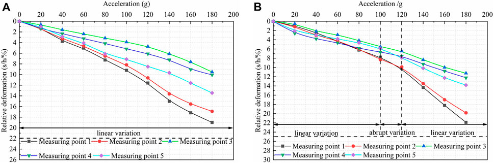
FIGURE 5. Relation between Δδ and a, (A) Natural water content, and (B) Saturated water content.
It can be observed from Figure 5 that the relative deformation of each measurement point of the model increases with the increase in acceleration under the condition of natural water content, and basically changes linearly. No obvious turning point is found overall, indicating that the model is stable under the condition of natural water content. However, the curve between the slope deformation and the centrifugal acceleration of the model in the saturated state turns sharply when the acceleration is between 100 and 120 g. It can be judged that the corresponding slope of the model is unstable at this time. By observing the monitoring video of the slope top, it was found that cracks appeared on the slope top when the model had an acceleration of 116 g.
According to the definition of the slope safety factor of the centrifugal test model in the study by Xu et al. (2004),
3.2 Analysis of Deformation Mode
Due to concerns on the centrifuge safety and stability of equipment, we did not perform a damage test under the state of natural water content. In addition, it was impossible to conduct an accurate measurement because some measurement points were buried in the soil during model making or due to small displacements; thus, we only obtained the displacement vectors of some measured points of the model. However, the possible slip surface positions of the slope can be analyzed based on this as shown in Figure 6.
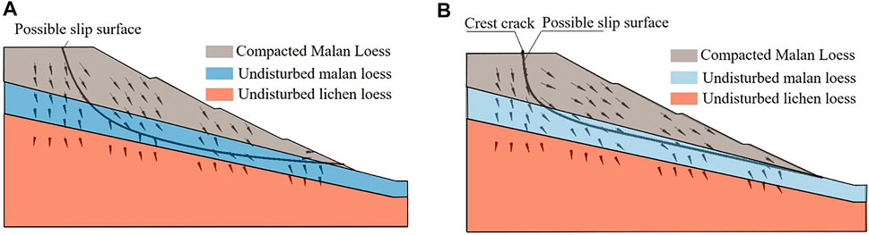
FIGURE 6. Displacement vector diagram and possible slip plane of model: (A) Natural water content, and (B) Saturated water content.
From Figure 6, it is clear that the deformation layers corresponding to the prototype slope of the test model under natural water content are mainly the compacted Malan loess layer at the top layer and the undisturbed Malan loess layer at the middle layer. Of the two, the top layer has a large deformation whereas the middle layer has a small one. In the saturated state, the strength of the filling body and the undisturbed Malan loess is greatly reduced. Moreover, the undisturbed Malan loess has collapsed; therefore, the deformation is large. In contrast, the bottom undisturbed Lishi loess layer is less affected by changes in the water content, and the deformation is still not noticeable.
In the state of natural water content, the possible slip surface of the model passes through the undisturbed Malan loess layer, and there is still a certain distance from the contact zone of each soil layer. Additionally, the upper soil layer on the slip surface does not show a complete overall slip pattern. This is because under the condition of natural water content, although the strength of the undisturbed Malan loess is weak, the difference in the strength of each soil layer cannot transform the undisturbed Malan loess layer near the contact zone into a weak interlayer; thus, the slip surface did not pass through the contact zone and the slip surface is approximately a circular arc. In the saturated state, the model slip surface passes through the top layer of the compacted Malan loess and the middle layer of the undisturbed Malan loess layer. This is due to the collapse of the undisturbed Malan loess in the middle layer when it saturates. At this state, the strength is greatly reduced, and the strength difference between the upper and lower soil layers becomes larger. Two weak intercalations are formed at the contact part of the adjacent soil layer. Because the depth of immersion is in the upper soft layer, the saturation of the upper soft layer is higher than that of the lower soft layer, and the normal stress of the lower soft layer is large. Therefore, the strength of the lower soft layer is still higher than that of the upper soft layer. When the slope is damaged, the upper soft intercalation would be damaged first, and the upper soil layer shows a typical overall sliding pattern.
It can be observed that whether the contact zone of each soil layer can form a weak interlayer depends on the strength difference between it and the adjacent soil layer. Only when the strength difference is large can a weak interlayer be formed. When the slope is unstable, the contact surface of each soil layer may not be a slip surface. However, if the contact surface forms a weak interlayer due to the large difference in strength between the upper and lower soil layers, the contact surface would be part of the failure surface, and the upper soil layer would appear as a more typical translational sliding pattern. On the contrary, the slip surface is approximately arc-shaped, and there is a transition layer between the contact surface with each soil layer.
It should be particularly pointed out that, in the saturated state, the top of the slope basically cracks along the line of the immersion hole, and the slope is damaged. It can be seen that in the actual project, similar slopes are likely to crack at vertical caves. The drainage of the slope should be ensured in the project. The crack on the model slope is presented in Figure 7.
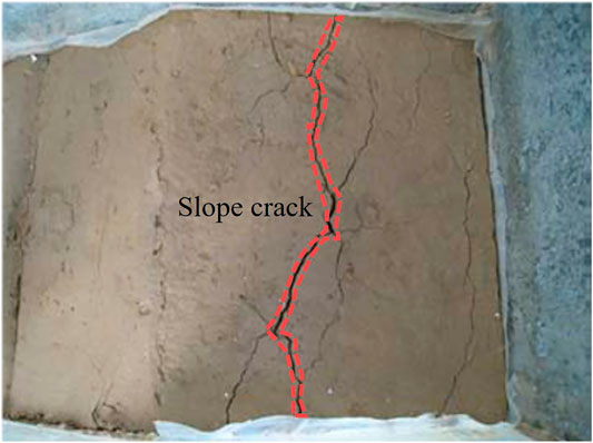
FIGURE 7. Slope crest cracking in saturated condition.
The analysis shows that the slip surface of the model under the natural water content and saturation state passes through the collapsible soil layer. Therefore, the strength of the collapsible soil layer determines the stability of the collapsible high slope.
3.3 Deformation After Construction
According to the basic principle of the centrifugal model test, when the acceleration is increased to 180 g, the construction of the prototype corresponding to the model is completed. At this time, the vertical settlement (deformation) of each measurement point can be referred to as the post-construction settlement at the corresponding position of the measurement point (deformation).
It can be observed from Figure 8 that the model corresponding to the prototype slope has a large deformation rate in 3 months after construction, which then gradually decreases. After 8 months, the deformation is basically stable, and the slope edge (measurement point 2) has the largest deformation after construction, which reaches 435.6 mm. It is followed by the slope top (measurement point 1), and the deformation of other measurement points (measurement points 3, 4, and 5) goes down the filling body and decreases as the thickness of the slope decreases (the thickness of the filling body in the text refers to the prototype at 180 g acceleration level). Moreover, it can be observed that the smaller the thickness of the slope, the shorter the time required for the slope deformation to become stable; conversely, the greater the thickness of the fill, the longer the consolidation time. Therefore, for this type of slope, it is recommended to stop the construction before completion of the filling body, and then fill to the design elevation after the deformation is basically completed to prevent excessive deformation after construction of the foundation.
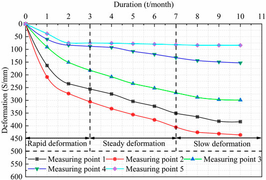
FIGURE 8. Under the condition of natural water content, post-construction deformation curve of undisturbed slope.
The post-construction deformation of the high-fill slope in the state of natural water content is mostly caused by the consolidation of the filling body. For a certain location, the thickness of the filling body is closely related to the post-construction deformation. In addition, since the test sensors are aimed at the top of the slope or the berm, the horizontal displacement of the slope has little effect on the change in the measured value of the sensor. Therefore, the measured values basically reflect the settlement of each measurement point. Considering the boundary conditions, the relationship between the thickness of the filling body H at the corresponding position of the prototype and the post-construction settlement s corresponding to the position can be analyzed by using the deformation of measurement points 2 to 5 on the slope surface, as shown in Figure 9.
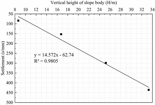
FIGURE 9. The relationship between the thickness of the filling body H at the corresponding position of the prototype and the post-construction settlement s.
From Figure 9, it is evident that there is a linear relationship between the thickness of the filling body and the settlement after construction, which conforms to the general law, indicating that the test results are relatively reliable. After completion of the actual project, the deformation at any position of the slope can be estimated by linear interpolation according to the settlement observation values at each step of the berm.
3.4 Deformation Analysis of Model Immersion
The vertical deformation curve of each measuring point in the model during immersion is exhibited in Figure 10. It can be observed from this figure that the expansion deformation of the model is produced in the process of water immersion. The deformation is mainly composed of two parts, namely deformation of the undisturbed Malan loess in the middle layer and that of the compacted Malan loess in the top layer, which are basically balanced within a certain time range at the beginning of the immersion; however, when the soil saturation reaches a certain level (because the water content of each layer of soil cannot be measured in real time, it was estimated that the saturation of the top and middle layers would be above 70% according to the amount of water injected), the deformation of the model changes abruptly and then remains stable.
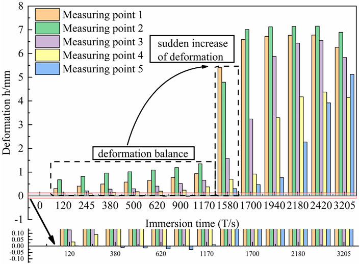
FIGURE 10. Immersion deformation curve of model.
It should be noted that the model is immersed in water at an acceleration of 1 g, and the model deformation does not meet the similarity rate. Furthermore, because the model is immersed for a short time, the model deformation does not include the consolidation deformation of the soil. Thus, it is necessary to compare and analyze the immersion deformation during model loading.
According to the operation process of the “single line method” and “double line method” in the data processing of loess immersion load tests, this test can compare and analyze the deformation when the water content of the model suddenly changes to saturation. However, since the centrifuge used in the test cannot be immersed into the water during the loading process, the “single line method” is no longer applicable. If the “double line method” is adopted, two identical models need to be loaded according to working condition 1; one of them is immersed in water, and then two models are loaded. This method has a large error and is difficult to complete. The loading systems of working condition 1 and condition 2 of this test are the same; the unloading curve of model working condition 1 is approximately regarded as the reloading curve of the model under the condition of natural moisture content in this study. By comparing this curve with the loading curve of the model in saturated state, the deformation difference of each measuring point under a certain acceleration level before and after the model is immersed, which is used to analyze the deformation law of the model when the soil moisture content suddenly changes to saturation, can be obtained. The calculation method of
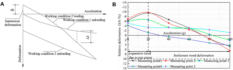
FIGURE 11. (A) Calculation schematic of
According to the abovementioned processing method, the relationship between the deformation and acceleration of the model slope before and after immersion in water (a ≤100 g) at different acceleration levels is obtained, as indicated in Figure 11B.
Figure 11B reflects the general law of settlement and deformation of the slope when the soil of the prototype slope is saturated. It should be particularly noted that the model appears to have a tendency of expansion and deformation relative to the state of natural water content at low acceleration levels, but this does not mean that the prototype slope corresponding to the model will undergo expansion and deformation when the soil is saturated. The reason for this error is that the model has the characteristics of uniform compaction of the filling body relative to the prototype, and lateral deformation is completely limited. Moreover, because the test uses the method of increasing model acceleration to increase the model self weight, the model soil self weight loading rate is large, and the permeability of cohesive soil is poor. The dissipation of excess pore water pressure caused by the increase in self weight stress in the model is too late, and the consolidation deformation of the model is not completed. Therefore, the deformation of the saturated state is not in accordance with the general law compared with the natural moisture content state at the low acceleration level, but with the increase in acceleration and the extension of loading time, the model finally shows a clear settlement deformation trend.
4 Numerical Analysis
4.1 High Fill Foundation Model
The three-dimensional finite element model is established by using the finite element software ABAQUS, as shown in Figure 12A. The original foundation and the filling material adopt M-C model. In the simulation process, the filling body is divided into 8 levels, the filling height of each level is 10 m, the longitudinal length of the model is 660 m, the transverse length is 370 m, and the height of the highest point of the model is 230 m, the unit type is tetrahedron element, the filling gully is approximately north-south direction, the front, rear, left and right side nodes of the model are subject to normal constraints, and the bottom is subject to fixed constraints, the filling process is simulated by the birth and death element method, and the foundation settlement results are obtained.
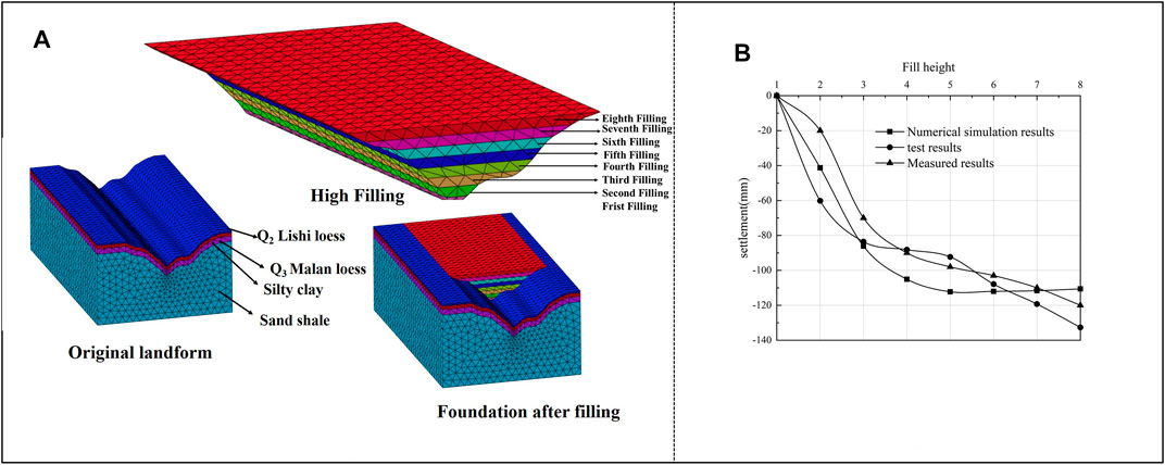
FIGURE 12. High fill foundation model (A) 3D finite element mesh model of high fill, (B) The comparison of numerical simulation results, centrifugal test results and field monitoring results.
The comparison of numerical simulation results, centrifugal test results and field monitoring results is shown in Figure 12B. It can be seen from the figure that the foundation settlement deformation trend obtained by the three methods is basically the same, and the difference is small. It can be considered that the method of using centrifugal model experiment and finite element method to simulate the surface settlement deformation law of high fill is accurate and can be used as an effective means to assist engineering design.
4.2 High Fill Slope Model
The strength reduction method is used to calculate the safety factor of high fill slope under natural water content and saturated state (He et al., 2021;Wang et al., 2022) It can be seen from Figure 13 that under natural water content, the plastic zone of high fill slope runs through from slope toe to slope crest, and the displacement of plastic zone is basically the same, with the safety factor of 1.68; In the saturated state, due to the increase of soil gravity, the sliding force increases, while the effective stress decreases and the shear strength attenuates, so the anti sliding force decreases. Due to the above factors, the plastic zone of high fill slope begins to develop near the slope toe, the soil is destroyed, and the safety factor is reduced to 1.32. Therefore, in slope construction, it is necessary to strengthen the inspection of the rationality of drainage system design to ensure slope safety.
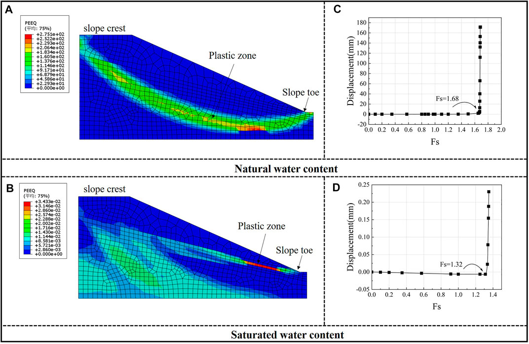
FIGURE 13. High fill slope model (A) Cloud diagram of natural water content plastic zone, (B) Cloud diagram of plastic zone in saturated state, (C) Safety factor in natural state, (D) Safety factor in saturated state.
5 Conclusion
(1) The high-fill slope of collapsible loess has good stability under the state of natural water content. The post-construction deformation and deformation rate are larger in the early stage and smaller in the later stage. The deformation of the filling body is the main factor that causes the entire slope deformation. There is a linear relationship between the thickness of the filling body and the post-construction settlement of the corresponding position.
(2) When the soil is saturated, settlement and deformation of the collapsible loess high-fill slope will occur. The consolidation of the filling body and the collapsibility of the soil layer will cause the settlement and deformation of the high-fill slope. The slope may crack along the weak zone formed by water immersion.
(3) The strength of the soil layer determines the stability of the collapsible loess. The slip surface will pass through the collapsible soil layer when the slope is damaged, and its position depends on the strength difference between the collapsible loess layer and its adjacent soil layer. When the strength difference causes a weak interlayer between the collapsing loess layer and the adjacent soil layer, the contact surface must be part of the slip surface; thus, the relatively weaker contact surface is damaged first, and the upper soil layer on the slip surface shows a typical translational sliding pattern. The slip surface is approximately circular, and there is a transition layer with a certain thickness between the slip surface and the contact surface. The moisture content of the high-fill slope has a greater effect on the settlement after slope construction and slope stability
(4) In the saturated state, the sliding force of soil increases, the shear strength decreases, and the stability of high fill slope decreases. Therefore, it is necessary to strengthen the inspection of the rationality of drainage system design in slope construction to ensure slope safety. The centrifugal model experiment is reliable in simulating the surface settlement deformation law of high fill and can be used as an effective means to assist engineering design.
Data Availability Statement
The original contributions presented in the study are included in the article/Supplementary Material, further inquiries can be directed to the corresponding author.
Author Contributions
YM: Conceptualization, Funding acquisition, Methodology, Supervision, Writing—review and editing. DZ: Data curation, Formal analysis, Writing—original draft, Validation, Visualization, Investigation. CH: Resources. XW: Resources. YZ: Resources. NX: Resources. WS: Resources.
Funding
The research described in this paper was financially supported by the National Natural Science Foundation of China (Grant No. 52178302), and the Key R & D Projects in Shaanxi Province (No. 2020SF-373).
Conflict of Interest
The authors declare that the research was conducted in the absence of any commercial or financial relationships that could be construed as a potential conflict of interest.
Publisher’s Note
All claims expressed in this article are solely those of the authors and do not necessarily represent those of their affiliated organizations, or those of the publisher, the editors and the reviewers. Any product that may be evaluated in this article, or claim that may be made by its manufacturer, is not guaranteed or endorsed by the publisher.
References
Alonso, B. E., Caicedo, B., and Thorel, L. (2014). Centrifuge Modelling of Unsaturated Soils[J]. J. Geo-Engineering Sci 2 (1-2). doi:10.3233/JGS-130013
Charles, W. W. N. (2014). Application of Advanced Simulation Technology of Geotechnical Centrifuge in Geotechnical Engineering of Hong Kong University of Science and Technology. J. Zhejiang University-Science A(Applied Phys. Engineering) 15 (01), 1–21. doi:10.1631/jzus.A0720090
Chen, J., and Tang, M. (2008). A Research of the Soil Cut High Slope Deformation Characteristics Based on Centrifugal Model Tests[J]. J. Chengdu Univ. Tech. (Science Tech. Edition) 5, 532–536.
Cheng, Y., Huo, A., Zhao, Z., and Peng, J. (2021). Analysis of Loess Fracture on Slope Stability Based on Centrifugal Model Tests. Bull. Eng. Geol. Environ. 80 (5), 3647–3657. doi:10.1007/s10064-021-02135-3
Drnevich, V. P., Santamarina, J. C., and Goodings, D. J. (1989). Centrifuge Modeling: a Study of Similarity. Geotechnical Test. J. 12 (2), 163. doi:10.1520/gtj10692j
Enomoto, T., and Sasaki, T. (2015). Several Factors Affecting Seismic Behaviour of Embankments in Dynamic Centrifuge Model Tests. Soils and Foundations 55, 813–828. doi:10.1016/j.sandf.2015.06.013
Fan, J., Jiang, D., Liu, W., Wu, F., Chen, J., and Daemen, J. (2019). Discontinuous Fatigue of Salt Rock with Low-Stress Intervals. Int. J. Rock Mech. Mining Sci. 115 (3), 77–86. doi:10.1016/j.ijrmms.2019.01.013
Fan, J., Liu, W., Jiang, D., Chen, J., Tiedeu, W. N., and Daemen, J. J. K. (2020). Time Interval Effect in Triaxial Discontinuous Cyclic Compression Tests and Simulations for the Residual Stress in Rock Salt. Rock Mech. Rock Eng. 53 (9), 4061–4076. doi:10.1007/s00603-020-02150-y
He, M., Zhang, Z., Zheng, J., Chen, F., and ning, L. (2021). Correlation between the Constant M(i) of Hoek-Brown Criterion and Porosity of Intact Rock[J]. rock Mech. rock Eng. 52(2), 923–936. doi:10.1007/s00603-021-02718-2
Hu, C., Mei, Y., and Wei, Y. (2012). A Method for Making Large-Scale Geotechnical Test Models Using Structural Undisturbed Loess: China. ZL 2, 9–28.
Hu, C. M., Mei, Y., Liu, Z., and Wang, X. Y. (2012). Deformation Mode and Stability Analysis of High Sticking Slope of Collapsible Loess. Yanshilixue Yu Gongcheng Xuebao/Chinese J. Rock Mech. Eng. 31, 2585–2592.
Hu, C. M., Mei, Y., and Wei, Y. (2012). A Method for Preserving Large-Scale Unsaturated Structural Undisturbed Soil Samples: China. ZL 7.
Jiang, D., Fan, J., Chen, J., Li, L., and Cui, Y. (2016). A Mechanism of Fatigue in Salt under Discontinuous Cycle Loading. Int. J. Rock Mech. Mining Sci. 86 (7), 255–260. doi:10.1016/j.ijrmms.2016.05.004
Jing, H. J., Gou, M. J., Zhang, Y. Q., and Song, K. I. (2021). Investigation on the Settlement of High Rockfill Embankment Using Centrifuge Tests. Front. Phys 9. doi:10.3389/fphy.2021.547991
Kang, Y., Fan, J., Jiang, D., and Li, Z. (2020). Influence of Geological and Environmental Factors on the Reconsolidation Behavior of fine Granular Salt. Nat. Resour. Res. 30 (1), 805–826. doi:10.1007/s11053-020-09732-1
Li, T., Tian, X., Han, W., Ren, Y., He, Y., and Wei, Y. (2013). Centrifugal Model Test Research on Sliding Failure of Pre-reinforced High-Fill Slope [J]. Rock Soil Mech. 34 (11), 3061–3070. doi:10.16285/j.rsm.2013.11.003
Li, X., Yang, S., Wang, Y., Nie, W., and Liu, Z. (2021a). Macro-micro Response Characteristics of Surrounding Rock and Overlying Strata towards the Transition from Open-Pit to Underground Mining. Geofluids 2021, 1–18. doi:10.1155/2021/5582218
Li, Y., Kitazume, M., Takahashi, A., Harada, K., and Ohbayashi, J. (2021b). Centrifuge Study on the Effect of the SCP Improvement Geometry on the Mitigation of Liquefaction-Induced Embankment Settlement. Soil Dyn. earthquake Eng. 148, 148106852. doi:10.1016/j.soildyn.2021.106852
Ling, H. I., Wu, M.-H., Leshchinsky, D., and Leshchinsky, B. (2009). Centrifuge Modeling of Slope Instability. J. Geotech. Geoenviron. Eng. 135, 758–767. doi:10.1061/(asce)gt.1943-5606.0000024
Liu, W., Zhang, X., Fan, J., Zuo, J., Zhang, Z., and Chen, J. (2020). Study on the Mechanical Properties of Man-Made Salt Rock Samples with Impurities. J. Nat. Gas Sci. Eng. 84, 103683. doi:10.1016/j.jngse.2020.103683
Liu, W., Zhang, Z., Fan, J., Jiang, D., Li, Z., and Chen, J. (2020). Research on Gas Leakage and Collapse in the Cavern Roof of Underground Natural Gas Storage in Thinly Bedded Salt Rocks. J. Energ. Storage 31, 101669. doi:10.1016/j.est.2020.101669
Luo, Q., Zhu, J., Zhang, R., Jiang, L., and Zhang, Z. (2018). Centrifuge Model Test of Sand Slope Stability [J]. J. rock Mech. Eng. 37 (05), 1252–1259. doi:10.1016/j.jrmge.2019.06.012
Mei, Y., Hu, C. M., Wei, Y., Zhang, W., Yuan, Y., and Wang, X. (2015). Centrifugal Model Test Research on Deformation Law of Q2, Q3 Loess Deep and Medium Fill Foundation [J]. Rock Soil Mech. 36 (12), 3473–3481.
Miao, F., Wu, Y., Li, L., Tang, H., and Li, Y. (2018). Centrifuge Model Test on the Retrogressive Landslide Subjected to Reservoir Water Level Fluctuation. Eng. Geology. 245, 169–179. doi:10.1016/j.enggeo.2018.08.016
Park, D. S., and Kutter, B. L. (2015). Static and Seismic Stability of Sensitive clay Slopes. Soil Dyn. Earthquake Eng. 79, 118–129. doi:10.1016/j.soildyn.2015.09.006
Peng, J., Fan, Z., Wu, D., Huang, Q., Wang, Q., Zhuang, J., et al. (2019). Landslides Triggered by Excavation in the Loess Plateau of China: A Case Study of Middle Pleistocene Loess Slopes. J. Asian Earth Sci. 171, 246–258. doi:10.1016/j.jseaes.2018.11.014
Schofield, A. N. (1980). Cambridge Geotechnical Centrifuge Operations. Géotechnique 30, 227–268. doi:10.1680/geot.1980.30.3.227
Shen, Z., Li, H., Wei, Y., and Fang, L. (2021). Centrifugal Model Test of Embankment Widening with Geogrid Treatment Technique. Arab J. Geosci. 14 (23). doi:10.1007/s12517-021-08844-z
Wang, J., Wang, T., Song, Z., Zhang, Y., and Zhang, Q. (2021). Improved Maxwell Model Describing the Whole Creep Process of Salt Rock and its Programming. Int. J. Appl. Mech. 13, 2150113. doi:10.1142/S1758825121501131
Wang, J., Wang, X., Zhang, Q., Song, Z., and Zhang, Y. (2021). Dynamic Prediction Model for Surface Settlement of Horizontal Salt Rock Energy Storage. Energy 235, 121421. doi:10.1016/j.energy.2021.121421
Wang, J., ZhangSong, Q. Z. P., Song, Z., Feng, S., and Zhang, Y. (2022). Nonlinear Creep Model of Salt Rock Used for Displacement Prediction of Salt Cavern Gas Storage. J. Energ. Storage 48, 103951. doi:10.1016/j.est.2021.103951
Wang, J., ZhangSong, Q. Z. P., Song, Z., and Zhang, Y. (2020). Creep Properties and Damage Constitutive Model of Salt Rock under Uniaxial Compression. Int. J. Damage Mech. 29 (6), 902–922. doi:10.1177/1056789519891768
Wang, X, Ma , Z, and Zhang, Y. (2022). Research on Safety Early Warning Standard of Large-Scale Underground Utility Tunnel in Ground Fissure Active Period. Frontiers in Earth Science. doi:10.3389/feart.2022.828477
Wang, X., Song, Q., and Gong, H. (2022). Research on Deformation Law of Deep Foundation Pit of Station in Core Region of Saturated Soft Loess Based on Monitoring. Adv. Civil Eng. 2022, 1–16. doi:10.1155/2022/7848152
Wu, K., Ni, W., and Wang, Y. (2017). Centrifuge Model Test for Deformation and Stability of High Fill Slope of Loess in the Gully Area. dteees 25, 81–85. doi:10.12783/dteees/apees2017/7662
Xu, G., Zou, G., and Wang, N. (2004). Failure Mode and Stability Analysis of Soil Slope on Inclined Bedrock[J]. Rock Soil Mech. 25 (5), 703–708.
Yan, K., He, J., Cheng, Q., Fan, G., Wang, Z., and Zhang, J. (2020). A Centrifugal Experimental Investigation on the Seismic Response of Group-Pile Foundation in a Slope with an Inclined Weak Intercalated Layer. Soil Dyn. Earthquake Eng. 130, 105961. doi:10.1016/j.soildyn.2019.105961
Yuan, B., Li, Z., Chen, Y., Ni, H., Zhao, Z., Chen, W., et al. (2022). Mechanical and Microstructural Properties of Recycling Granite Residual Soil Reinforced with Glass Fiber and Liquid-Modified Polyvinyl Alcohol Polymer. Chemosphere 286, 131652. doi:10.1016/j.chemosphere.2021.131652
Yuan, B., Li, Z., Zhao, Z., Ni, H., Su, Z., and Li, Z. (2021). Experimental Study of Displacement Field of Layered Soils Surrounding Laterally Loaded Pile Based on Transparent Soil. J. Soils Sediments 21, 3072–3083. doi:10.1007/s11368-021-03004-y
Zhang, G., and Wang, L. (2017). Simplified Evaluation on the Stability Level of Pile-Reinforced Slopes. Soils and Foundations 57, 575–586. doi:10.1016/j.sandf.2017.03.009
Zhang, S., Pei, X., Wang, S., Huang, R., Zhang, X., and Chang, Z. (2019). Centrifuge Model Testing of a Loess Landslide Induced by Rising Groundwater in Northwest China. Eng. Geology. 259, 105170. doi:10.1016/j.enggeo.2019.105170
Keywords: slope engineering, centrifugal model test, collapsible loess, high filling, deformation characteristics
Citation: Mei Y, Zhou D-b, Hu C-m, Wang X-y, Zhang Y, Xiao N and Shi W (2022) Study on Deformation Characteristics of Loess Ultrahigh-Fill Slope Based on Large-Scale Undisturbed Soil Centrifugal Model Tests. Front. Earth Sci. 10:848542. doi: 10.3389/feart.2022.848542
Received: 04 January 2022; Accepted: 21 February 2022;
Published: 08 March 2022.
Edited by:
Jinyang Fan, Chongqing University, ChinaReviewed by:
Pingping Luo, Chang’an University, ChinaMingming He, Xi’an University of Technology, China
Copyright © 2022 Mei, Zhou, Hu, Wang, Zhang, Xiao and Shi. This is an open-access article distributed under the terms of the Creative Commons Attribution License (CC BY). The use, distribution or reproduction in other forums is permitted, provided the original author(s) and the copyright owner(s) are credited and that the original publication in this journal is cited, in accordance with accepted academic practice. No use, distribution or reproduction is permitted which does not comply with these terms.
*Correspondence: Dong-bo Zhou, emRiQHhhdWF0LmVkdS5jbg==