 Changjiang Wu1,2
 Jun Yu
95% of researchers rate our articles as excellent or good
Learn more about the work of our research integrity team to safeguard the quality of each article we publish.
Find out more
ORIGINAL RESEARCH article
Front. Earth Sci. , 03 February 2022
Sec. Structural Geology and Tectonics
Volume 10 - 2022 | https://doi.org/10.3389/feart.2022.837950
This article is part of the Research Topic Applications of Geotechnical Mechanics in Underground Engineering View all 41 articles
The technology of pile wall combination in a deep foundation pit is a kind of technology to resist soil and water pressure by using the great stiffness of the retaining pile and basement wall. As a part of basement wall, the retaining pile can reduce the thickness of the basement wall. However, the influence of excavation deformation and the interaction mechanism between the retaining pile and basement wall are ignored in the current design theory of the pile wall combination in a deep foundation pit. Therefore, we proposed a composite structure model of an elastic subgrade beam associated with a continuous beam, and introduced an elastic spring to simulate the interaction between the pile and basement wall. The finite difference equation and calculation method were established to figure out the internal force and displacement of the pile wall combination structure, which was able to accurately calculate the internal force and deformation of the retaining pile during the excavation stage. Based on the above results, further investigation was carried on the interaction between the pile and basement wall during the construction and normal service stage of the basement structure. It was concluded that the basement wall could reduce the lateral displacement on the top of the retaining pile caused by removal of the strut and affect the bending moment of the upper part of the retaining pile among the depth of the basement wall. The bending moment of the basement wall was closely related to the deformation of the retaining pile and changes with the working condition. In addition, the results of factor sensitivity analysis showed that the pile-wall relative stiffness ratio, stiffness of the horizontal beam, and slab of the basement had a significant influence on the interaction between the pile and basement wall.
With the pace of urbanization accelerating and the scale of underground space development getting larger and larger, lots of deep foundation pit projects have been initiated, and the design and construction requirements of retaining the structure for deep excavation are getting higher and higher. Most of the retaining structures of foundation pits are regarded as temporary components, which will be abandoned in the soil after the completion of underground structure construction, resulting in a large amount of resources waste. In the soft soil area with high phreatic level and high protection demand of the surrounding environment, large-diameter bored piles with greater horizontal stiffness are often used as the main temporary retaining structure in deep foundation pit engineering with more than two floors. If the basement wall of the underground structure can be combined with the retaining pile to form the permanent component of the basement, then, the thickness of the basement wall will be greatly reduced because the bending strength of the retaining pile is fully utilized, and a lot of building materials and energy will be saved. The pile wall combination structure was first adopted in the foundation pit of the Headquarters Building in Chiyoda District, Tokyo, Japan, and subsequently applied in projects such as Bellconnon in London, Seoul in South Korea, Singapore Maritime Museum, and the Taipei 101 building (Mirza, 1996). The technology pile wall combination structure worked effectively in those above projects. Xia et al. (2004) put forward the technical concept of “one pile three uses” firstly in civil construction engineering in China. In recent years, with the accumulation and improvement of the practice level of deep foundation pit design and construction, the new design concept of “pile wall combination” has been recommended in the new Shanghai version of “Technical Standards for Foundation Pit Engineering” (Technical Code for Excavation Engineering (DG/TJ08-61-2018), 2018). Its aim is to provide some fundamental basis for the practice of deep foundation pit engineering.
However, there are only a few cases of deep foundation pits using the technology of pile wall combination in China, and this technology is often passively adopted when there is insufficient construction space for the structure within the red line of land. The technology of pile wall combination has not been widely adopted in practice engineering, mainly due to the following reasons: 1) The internal force distribution law between the pile wall combination structure needs to be further discussed. The current design standard suggests that the pile and basement wall bear together the static earth pressure according to the relative bending stiffness of the pile wall combination structure when they both bear the water pressure separately. However, the influence of different factors is not considered from the mechanism of the interaction between the pile wall combination structure; 2) for the same retaining structure of the foundation pit, different construction schemes, geological conditions, and other factors will lead to different deformation behaviors of retaining piles induced by deep excavation (Li et al., 2007; Xu et al., 2009; Liao et al., 2015). The bearing capacity of deformed bored piles will be weakened. But the current design ignores the influence of deformation behavior on the mechanical property of the pile wall combination structure; and 3) after the implementation of the pile wall combination structure technical plan, a large amount of post field monitoring data are needed as further support. The monitoring data derived from only a few cases of pile wall combination structure projects are relatively limited (Hu et al., 2015), and the monitoring lasting time is very short, which is not enough to reflect the performance status of the pile wall combination structure in the permanent service stage.
This article mainly focuses on the pile wall combination structure of deep foundation pits in soft soil areas. Considering the influence of deformation of the retaining piles during the entire excavation process of the foundation pit, the finite difference calculation method is adopted to establish the theoretical calculation model equations for the pile wall combination structure. The model is used to analysis the mechanism of the interaction between the retaining piles and basement wall and explore the deformation development and internal force distribution between the basement wall and retaining piles. The new method not only improves the design theory of the pile wall combination structure under the condition of a high phreatic level in soft soil areas, but also provides support for solving the key technical problems of the pile wall combination structure in deep foundation pit projects, so as to further improve the design and construction ability of China’s deep foundation pit engineering.
For retaining pile structures, the current calculation design methods include the equivalent beam method, continuous beam method, and elastic resistance method, etc (Gao, 1995), among which the elastic subgrade beam method is the most popular, and the specific calculation method can be divided into two types: the total amount method and the incremental method (Yang, 2004), as shown in Figure 1. When the total amount method is adopted, the water pressure and earth pressure outside the pit under each working condition are applied to the retaining structure at the same time, and the internal struts are also working at the same time. The actual internal force and deformation of the structure under the corresponding working condition can be calculated. However, the incremental method can consider the initial deformation of the retaining structure before the installation of internal struts. The actual situation is that the retaining structure has accumulated a certain displacement before the struts work. It has been proved by practice that the internal force and deformation of the retaining structure is closely related to the initial displacement during the installation of struts. Therefore, the incremental calculation method can better reflect the true working behavior of the supporting structure.
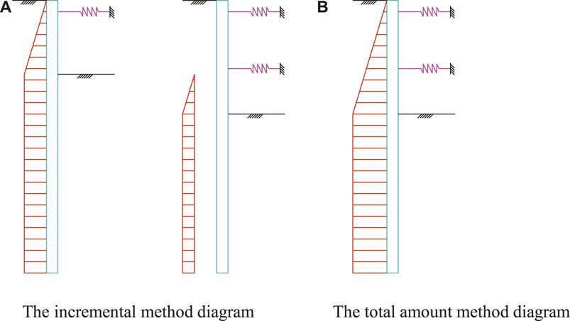
FIGURE 1. Calculation diagram of the retaining structure section. (A) The incremental method diagram. (B) The total amount method diagram.
Feng et al. (2009) employed the iterative incremental method to study the stress behavior of the underground diaphragm wall by the finite element method of elastic subgrade beams; Liu and Chen (2018a), Liu and Zhang (2018b) improved the load increments of retaining structure under different construction conditions on the basis of traditional incremental method. Later, they proposed an incremental calculation model based on the p-y curve that can consider the initial displacement of the retaining wall, and obtained results that are very consistent with the field monitoring results. The above achievements are all studies on the internal force and deformation of the braced retaining structure during deep excavation. However, the stage of the combination of the retaining pile and basement exterior wall after completion of the basement exterior wall construction is not involved, and the problem of interaction between the pile and wall is still unsolved. Wang and Shen (2012) proposed that the pile wall combination structure can be designed through multiple working conditions such as the foundation pit excavation stage, normal service stage, and anti-seismic stage. They pointed out that the analysis method of retaining piles in the excavation stage is the same as the conventional method used in deep excavation. In the service stage, the retaining pile can be taken as a multi-span continuous beam. The water pressure imposes on the retaining pile along with the static earth pressure outside the pit, and the load applied on the basement wall includes the water pressure and the static earth pressure which is distributed according to the bending strength ratio of the pile wall combination structure. Although this method is very suitable for engineers to master, it does not consider the unfavorable factor of deformation. The interaction between the pile and basement wall under various working conditions lacks further analysis, and the law of internal force and deformation of the pile wall combination structure is still unclear.
In view of the above shortcomings, under the premise of the incremental method based on the elastic subgrade beam model, the finite difference equations and methods for calculating the lateral displacement, internal force, and deformation of the retaining pile and basement wall are established. The influence of factors such as the pile wall stiffness ratio, the load level, and the horizontal stiffness of the basement floor on the interaction between the pile and basement wall are considered. In this method, the pattern of incremental load and incremental displacement is used to calculate the deformation of the retaining structure induced by the excavation stage, considering the interaction of the pile wall combination structure during the construction of the basement.
A simplified calculation model for the whole process of foundation pit construction considering the pile wall combination structure is shown in Figure 2. Different from conventional braced pile retaining construction, the pile wall combination structure means that the basement retaining piles and basement wall form into a composite structure which can bear the water and earth pressure outside the pit through the horizontal beam and slab of basement together during the construction and service stage. Therefore, the contribution of the retaining piles and basement wall should be considered at the same time when in the strut removal stage and service stage, along with the pile deformation induced by deep excavation.
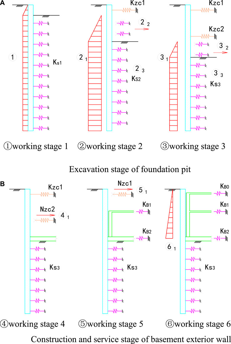
FIGURE 2. Calculation diagram of the whole construction process of the foundation pit ① Working stage 1 ② Working stage 2 ③ Working stage 3. (A) Excavation stage of the foundation pit ④ Working stage 4 ⑤ Working stage 5 ⑥ Working stage 6. (B) Construction and service stage of the basement exterior wall.
When the incremental method is applied for calculation, the load increases from the previous working stage to the current working stage. It includes the increment of water and earth pressure outside the pit (①, ②1, ③1, ⑥1), the horizontal earth resistance by excavation inside the pit (②2, ③2), the resistance released by the reduction of the horizontal earth resistance coefficient of the soil below the excavation surface (②3, ③3), and the axial force for strut by removal (④1, ⑤1).
The increase in magnitude of water and earth pressure outside the pit is that of the difference behind the retaining pile outside the pit between the previous working stage and the current working stage. It needs to be noted that during the service stage of the basement, ⑥1 means the difference between the static earth pressure and the active earth pressure outside the pit.
In working stage 3, the load increment released by the excavation of soil is the product of the horizontal resistance coefficient of the excavated soil and the cumulative horizontal displacement of the retaining pile in working condition 2. According to the design code, the horizontal resistance coefficient
Where m is the proportional coefficient of the horizontal earth resistance coefficient increasing with depth (kN/m4); z is the depth of the calculation point from the ground (m); and hi is the excavation depth of the foundation pit under the calculation stage (m).
For the increment ∆Fs released by the decrease of the horizontal earth resistance coefficient below the excavation surface, it can be calculated as follows:
Where ks,i-1 and ks,i are the horizontal earth resistance coefficient of the soil below the excavation surface under the previous working stage and the calculated working stage (kN/m3); and w is the cumulative horizontal displacement of soil under the previous working condition (m).
In addition, during the strut removal and basement construction stage, the axial load Nzc,i released due to strut removal can be calculated as follows:
Where kzc,i is the stiffness of support (kN/m/m).
The elastic spring is introduced to simulate the interaction between the piles and the basement wall during the construction and permanent service of the basement (as shown in Figure 3). Therefore, the deflection equations of the retaining piles based on the vertically placed elastic subgrade beam model are shown in Eqs. 4, 5, respectively.
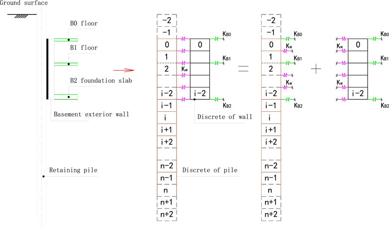
FIGURE 3. Discrete analysis of the pile wall combination structure.
Foundation pit excavation stage:
Basement construction and service stage:
Where E is the elastic modulus of retaining piles (kPa); I is the moment of inertia of the retaining pile section (m4); kB,i is the stiffness of the foundation slab or floor (kN/m/m); kw is the interaction stiffness of the elastic spring between the piles and basement wall, which is defined by the thickness of the plain concrete in the gap between the retaining pile and basement exterior wall with the equation
In order to simplify the calculation, the above fourth-order differential equations are solved by the finite difference method. The retaining piles are discretely divided into n+5 elements (two virtual node elements at the top and bottom of the pile), and the basement wall is discretely divided into i+1 node elements, each of which has a length of h. Only the stiffness of the retaining pile is considered during the excavation stage when the combined stiffness of the pile and wall is considered comprehensively during the construction stage of the basement. According to the finite difference principle, the differential terms in Eqs. 4, 5 can be transformed into the following equations:
It is assumed that the bending moment M and the shear force Q at the end of the retaining pile are both zero:
Using the finite difference method, the second and third differential terms of the above formula can be expressed as:
Combining Eqs. 7, 8, the horizontal displacement of virtual element nodes is obtained as follows:
Thus, Eqs. 4, 5 can be written in matrix form:
Where [K] is the displacement stiffness matrix of the retaining pile; [KZC] is the displacement stiffness matrix of the strut; [KB] is the displacement stiffness matrix of the beam and slab of basement floor which replaced the strut; [Ks] is the displacement stiffness matrix of foundation soil; [Kw] is the displacement stiffness matrix between the pile and wall; [P] is the column vector of the load increment; and [w] is the displacement column vector of the pile wall combination structure. After substituting the node displacement of the virtual element, each stiffness matrix is expressed as follows:
Where [KZC], [KB], [Ks], and [Kw] should be determined according to the actual construction stage of the foundation pit. Eqs. 10, 11 can be further simplified as follows:
Where [K]−1 is the inverse matrix of [K]. After obtaining the displacement vector [w] of the retaining structure, the bending moment [M] of the retaining pile can be obtained according to Eqs. 21–23.
Where KM is the matrix coefficient of the bending moment, as shown in the following formula:
According to formula Eqs. 25, 26, in the construction and service stage of the basement, the squeezing load [N] on the basement exterior wall can be calculated, and finally the internal force of the basement wall can be calculated according to the multi-span continuous beam method.
After the establishment of related matrix equations, a computational program edited by MATLAB Language is apply to solve the equations, and it is proved that it is very efficient. Based on the principle of finite difference, the design theory of the pile wall combination structure for deep excavation proposed in this section is not only suitable for a conventional temporary retaining structure, but also for deep foundation pit projects using the technology of pile wall combination for more than two floors underground.
The Shanghai Changxing Science and Technology Plant Project is located in Caohejing Development Zone, Xuhui District, Shanghai. The excavation area of the foundation pit is about 10,000 m2, and the circumference of the retaining structure is 400 m around. There are two floors underground and the excavation depth is about 10.5 m. The physical and mechanical properties of soil are shown in Table 1. The foundation pit adopts a Φ950@1,100 bored pile and two layers of reinforced concrete horizontal struts with a Φ850@600 three-axis cement mixing pile used for the waterproof curtain. Two layer struts are located respectively at an elevation of −1.50 m and −6.50 m. The typical profile of the retaining structure is shown in Figure 4.
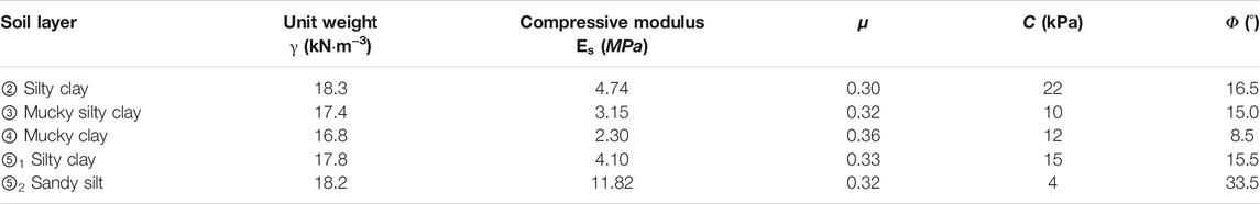
TABLE 1. Physical and mechanical parameters of soils.
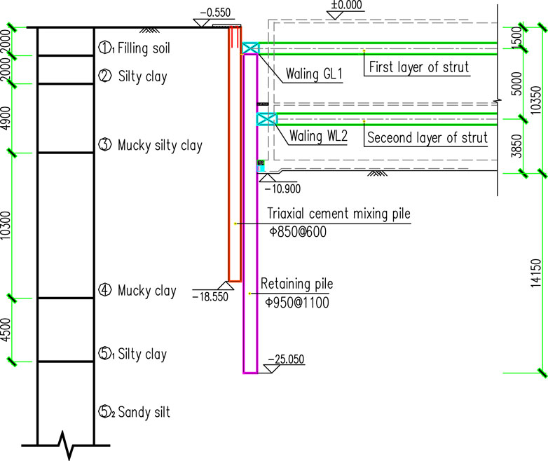
FIGURE 4. Typical profile of the retaining structure.
The basement wall’s thickness is 500 mm. Although the pile wall combination structure design is not adopted in this project, the deformation of field monitoring data of the foundation pit can verify the rationality of calculation results from the finite difference method proposed. At the same time, it is supplemented by the analysis results of the finite element software for further comparison.
Figure 5 shows the comparison results of the lateral displacement of retaining piles using the finite element method, finite difference method, and field monitoring during the excavation stage. It can be seen from Figure 5 that Eq. 1 in working stage 2, the maximum lateral displacement of retaining piles calculated by the finite element method and finite difference method are all about 14 mm which is very consistent with that from the field monitoring result. The deformation curves are all in parabolic shape, but the depth positions of the maximum lateral displacement are a little different. The depth of the maximum lateral displacement from field monitoring is about 9.5 m, which is 2 m deeper than that from calculation. The difference between the finite element and finite difference calculation results is within 1 mm; 2) in working stage 3, the maximum lateral displacement difference of each field monitoring point is between 29 and 34 mm while the maximum lateral displacements calculated by the finite element method and finite difference method are about 27 mm, and the monitored maximum lateral displacement depth is relatively 3 m lower. However, the results of the finite element method and finite difference method are still highly consistent. It can be seen that the finite difference method can reflect the deformation behavior of the retaining pile very well during the excavation of the foundation pit.
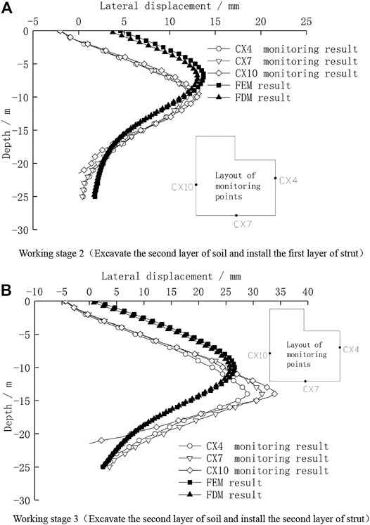
FIGURE 5. Lateral displacement of retaining piles during the foundation pit excavation. (A) Working stage 2 (Excavating the second layer of soil and installing the first layer of the strut). (B) Working stage 3 (Excavating the second layer of soil and installing the second layer of the strut).
Figure 6A shows the comparison of the field monitoring and theoretical calculation results of lateral displacement of the retaining pile under working stage 4. Whether it is the field monitoring or calculation result, the removal of the second layer strut after the construction of the foundation slab has a very small impact on the deformation of the retaining piles. The main reason is that the environmental protection requirements around the foundation pit are relatively high, and the selected retaining piles have strong stiffness, so the secondary deformation caused by removing a strut is very small which does not exceed 10% of the deformation generated during the excavation stage (Wu et al., 2018). In addition, the deformation characteristics of the retaining pile are basically the same as the situation under working stage 3. At the same time, the calculation results of the finite element method and finite difference method are also highly consistent. This fully proves again that the proposed finite difference method is suitable for the deformation analysis of retaining piles caused by the excavation of the foundation pit. Therefore, although the above engineering project did not adopt the pile wall combination structure technology, this article continued to adopt the finite difference method to further analyze the interaction between the bored pile and basement wall based on the comparison of the above-mentioned foundation pit excavation stage data.
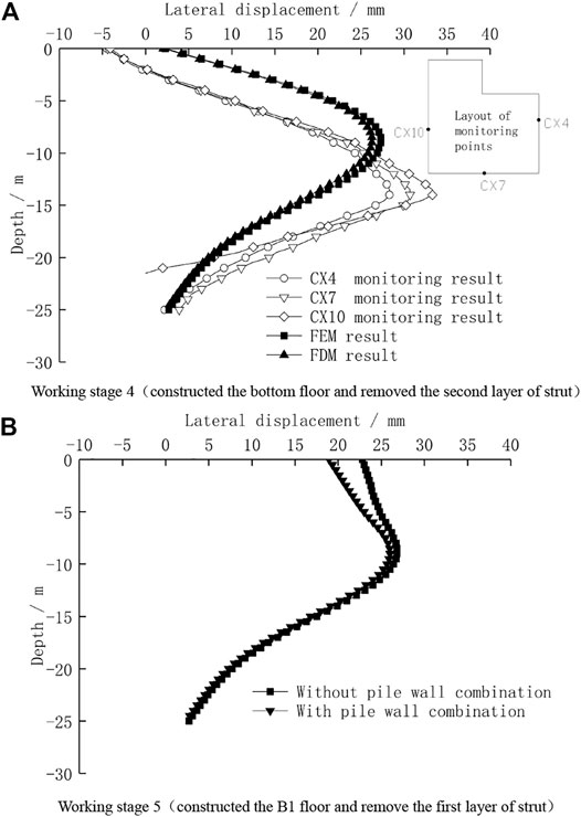
FIGURE 6. Lateral displacement of retaining piles during construction of the basement. (A) Working stage 4 (Constructing the bottom floor and removing the second layer of the strut). (B) Working stage 5 (Constructing the B1 floor and removing the first layer of the strut).
Figure 6B shows the comparison of the finite difference calculation results of the lateral displacement of retaining piles when the pile-wall integration technology is adopted or not under working stage 5. After the construction of the B2 basement exterior wall and B1 beam and slab is completed, the wall and retaining pile combines and becomes a composite structure which has stronger stiffness to resist the horizontal load outside the pit. And when the first layer strut is removed, the induced lateral displacement of the cantilever section of the retaining pile is smaller due to the pile wall combination structure technology. The lateral displacement on the top of the retaining pile decreases to 19 mm, while it is 23 mm without the pile wall combination structure technology. Therefore, the pile wall combination structure technology can take advantage of the lateral stiffness of the basement exterior wall to reduce the lateral displacement on the top of the retaining pile caused by the removal of a strut, and then control the impact on the buildings outside the pit.
Figure 7 shows the comparative results of the internal force of retaining piles using different calculation methods during the excavation stage of the foundation pit. In the excavation stage, before the resistance effect of the basement exterior wall has worked yet, the distribution law of the retaining pile internal force obtained by the two calculation methods is almost the same, and the maximum magnitude of calculated positive and negative bending moments is very close. This further shows that the results calculated by the finite difference method and commercial finite element software are also very consistent before the construction stage without considering the effect of the pile wall combination structure. Therefore, the finite difference calculation method proposed in this article can accurately and reasonably analyze the effect of the pile wall combination structure in the subsequent construction and service stages.

FIGURE 7. Bending moment of the retaining pile during different excavation stages.
Figure 8A shows the bending moment distribution of the pile wall combination structure under the construction stage of the basement, where Mp is the bending moment of retaining pile, and Mw is the bending moment of basement wall. In order to better study the internal force characteristics of the pile wall combination structure, the bending moment Mp’ of the conventional foundation pit without the pile wall combination structure technology under this working stage is compared with the finite element method. It can be seen from the figure that when the construction of the B1 beam and slab is completed and the first layer strut is removed, the basement exterior wall is squeezed by the retaining piles and a bending moment will be produced. Therefore, compared with the Mp’ of the temporary retaining pile, the Mp of the retaining pile with the pile wall combination structure becomes slightly smaller when the depth is above 7.5 m, and the Mp is basically the same when the depth is below 7.5 m. The bottom of the basement wall is restricted by the foundation slab and a negative bending moment will appear. The other parts of the basement wall will have positive bending moments. In addition, the calculation results show that after the strut is removed, the upper part of the basement wall and the retaining pile are squeezed against each other, while the lower part of the basement wall and the retaining pile are separated from each other. So the basement wall has almost no effect on the internal force of the lower part of the retaining pile. However, according to the entire construction process, the internal force control section of the retaining pile is located below the excavation surface, and the basement wall almost has no effect on the maximum internal force of the retaining pile section.
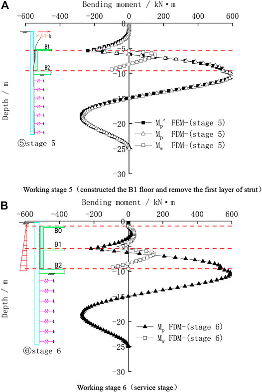
FIGURE 8. Bending moment of the pile wall combination structure during construction and service stage of the basement. (A) Working stage 5 (Constructing the B1 floor and removing the first layer of the strut). (B) Working stage 6 (Service stage).
Figure 8B shows the bending moment distribution of the pile wall combination structure during the normal service stage. Since the active earth pressure outside the pit is converted into static earth pressure, the negative bending moment of retaining piles at depths above the B1 floor decreases and the positive bending moment appears. The bending moment distribution of retaining piles at depths below the B1 floor does not change much. Due to the support of the B1 floor, the basement wall is taken as a continuous beam.
In order to further study the interaction between piles and walls, the bending moment of the retaining pile and basement exterior wall under working stages 5 and 6 are selected for comparative analysis, as shown in Figure 9. It can be seen from Figure 9A that for the internal force of retaining piles, with the increase of earth pressure outside the pit, the retaining piles at the mid-span part from the B1 floor to the B0 floor change from the negative bending moment to the positive bending moment, and the maximum magnitude is 20 kN m. The negative bending moment at the support of the B1 floor has been increased from -203 kN m to -218 kN m. Ranging from the depth of the B1 floor to −7.0 m, the negative bending moment of the retaining pile increases, while the positive bending moment decreases a little. The deeper the depth, the less the amplitude of the bending moment changes. The bending moment of the retaining pile below the depth of −7.0 m does not change much. It can be seen from Figure 9B that for the internal force of the basement exterior wall, the negative bending moment of the wall in the depth range from B2 floor to B1 floor decreases. The positive bending moment first decreases and then increases with the depth, and the negative bending moment decreases with the depth. The maximum positive bending moments between two working stages are 150 kN m and 145 kN m, respectively and the maximum negative bending moments are -100 kN m and −91 kN m, respectively. For the bending moment of the wall in the depth range from the B0 floor to B1 floor, the maximum positive bending moment is 35 kN m, and the maximum negative bending moment is −44 kN m.
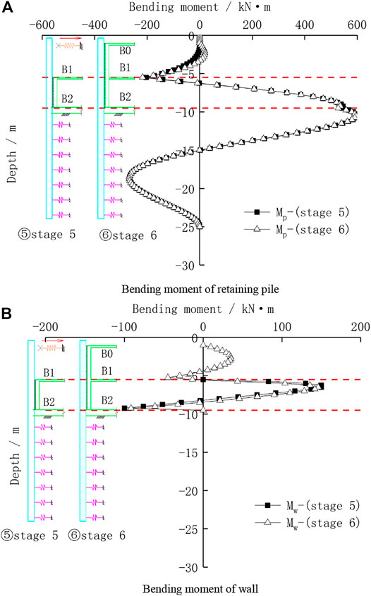
FIGURE 9. Bending moment of the pile wall combination structure under different stages. (A) Bending moment of the retaining pile. (B) Bending moment of the wall.
In summary, in the construction and service stage, the wall of the pile wall combination structure has an impact on the internal force of the retaining pile within the range of the existing wall, but has little impact on the internal force of the retaining pile below the bottom of the wall. The maximum internal force section of the retaining pile is often below the bottom of the pit, so the internal force of the retaining pile of the pile wall combination structure can be designed according to the conventional excavation stage. The internal force of the basement exterior wall changes with the different working stages. Thus, the design of the wall should consider the different working stage and the deformation of the retaining pile induced by excavation.
In order to further analyze the pile wall combination structure interaction mechanism, the stiffness ratio of the pile wall combination structure and the stiffness of the horizontal beam and slab of the basement under the service stage of the basement are selected for sensitivity analysis, and the finite difference calculation method of the pile wall combination structure is adopted.
According to the conventional design, the thickness of a two-story basement wall in Shanghai usually ranges from 400 to 600 mm, so the wall thickness is selected as 400 mm, 500 mm, and 600 mm, respectively to study the interaction of the pile wall combination structure under the different conditions of stiffness ratio. Figure 10 shows the bending moment distribution of the pile wall combination structure under different stiffness ratios.
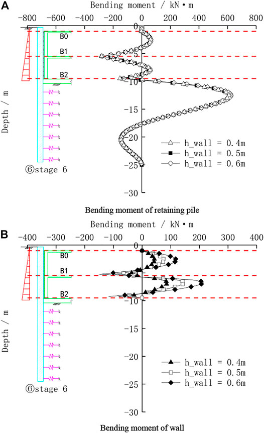
FIGURE 10. Bending moment of the pile wall combination structure with different pile wall stiffness ratios. (A) Bending moment of the retaining pile. (B) Bending moment of the wall.
As displayed in Figure 10A, for the bending moment of the retaining pile, the change in the thickness of the wall has a very small effect on the bending moment of the retaining pile between the B1 floor and B2 floor. The thicker the wall, the greater the negative bending moment of part of the piles. It has almost no effect on the bending moment of the retaining pile below the excavation surface. From Figure 10B, it shows that for the bending moment of the wall, the thickness of the wall has a great influence on the bending moment of the pile. As the thickness of the wall increases, the positive bending moment of the wall in the middle span between basement floors increases, and the negative bending moment at the floor bearing also increases. The main reason is that from the construction stage to the service stage, due to the increase of earth pressure, the lateral displacement of the pile wall combination structure is very small, thus the impact on the bending moment of the retaining pile is correspondingly small, and the basement wall has a large change in stiffness due to the increase of wall thickness, so the bending moment of the wall has a significant change.
According to the conventional design, the thickness of the foundation slab in a two-story basement in Shanghai is usually between 600 and 800 mm, and the thickness of the floor slab is between 120 and 250 mm. Regardless of beams, pillars, and piles in the basement, the stiffness ratio between the floor and the foundation slab is between 0.15 and 0.4. Therefore, it is assumed that the stiffness of the foundation slab is a fixed value, and the stiffness ratio is selected as 0.15, 0.25, and 0.35 to study the internal force distribution law between the retaining pile and wall under the condition of different floor slab stiffness. Figure 11 shows the bending moment distribution of the pile wall combination structure under different floor slab stiffness conditions.
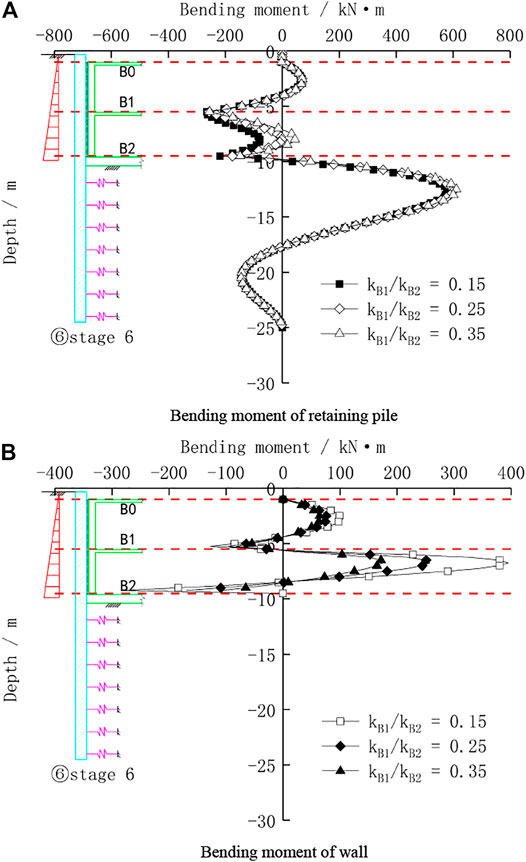
FIGURE 11. Bending moment of the pile wall combination structure with different stiffnesses of the horizontal beam and slab. (A) Bending moment of the retaining pile. (B) Bending moment of the wall.
It can be seen from Figure 11A that for the bending moment of the retaining pile, the stiffness change of the horizontal floor slab has a significant effect on the bending moment of the retaining pile between the B1 floor and the B2 floor. The variation of the bending moment of the pile in this part becomes larger with the stronger stiffness of the floor slab. The bending moment of the pile in this part is all negative at the beginning, and then it develops into a positive bending moment in the middle of the span, but the maximum magnitude of the negative bending moment at the floor bearing is almost unchanged. In addition, it has little effect on the bending moment of the pile below the excavation surface. It can be seen from Figure 11B that the change in the stiffness of the floor slab has a greater impact on the bending moment of the wall. This is mainly because the lateral displacement of the retaining pile decreases after the increasing of floor slab stiffness, and the squeezing effect on the basement wall is also reduced, so the internal force of the wall is correspondingly reduced.
Based on the elastic subgrade beam model, a finite difference calculation method for a deep foundation pit using the pile wall combination structure considering the excavation deformation was proposed. The main conclusions are as follows:
1) In the excavation stage of the deep foundation pit, the simplified analytical algorithm proposed for the internal force and deformation of the retaining pile is in good agreement with the field monitoring and commercial finite element analysis results, indicating that the finite difference calculation method suggested can accurately calculate the internal force and deformation of the retaining pile during the excavation stage.
2) During the construction and service stage of the basement, a composite structure model of the elastic subgrade beam and continuous beam was proposed. For simulating the interaction between the retaining pile and wall, the elastic spring element was introduced. The calculation results show that the basement exterior wall can reduce the lateral displacement of the top of the retaining pile caused by the dismantling of the strut. And the wall has an impact on the internal force of the upper pile of the retaining pile within the range of the existing wall, but has little impact on the internal force of the retaining pile below the wall.
3) Whether in the excavation stage or the service stage, the maximum internal force section of the retaining pile is often below the bottom of the pit, so the internal force of the retaining pile with the pile wall combination structure can be determined according to the conventional excavation stage. The internal force of the basement exterior wall changes with the working stages, so the design of the wall should be closely considered with the working stages along with the deformation of the retaining pile.
4) Sensitivity factors analysis on the interaction of the pile wall combination structure shows that the increase in the thickness of the basement wall has little effect on the bending moment of the retaining piles, but the bending moment of the basement wall changes significantly. When the stiffness of the basement floor slab increases, the bending moment of the retaining pile above the excavation surface changes significantly, and the internal force of the wall decreases accordingly.
The raw data supporting the conclusions of this article will be made available by the authors, without undue reservation.
CW was responsible for defining the research aims, collating and reviewing the literature and previous research for the discussion, conceptualizing the article structure, writing the manuscript draft, and figure conception and execution. XC and JY jointly agreed upon the research objectives; provided supportive analyses and interpretations; and contributed, reviewed, and edited text. WS contributed and edited text.
This work is financially supported by the Jiangsu Natural Science Foundation Youth Project (Grant Nos. BK20180954), the National Natural Science Foundation Youth Project of China (Grant Nos. 11,802,145).
The authors declare that the research was conducted in the absence of any commercial or financial relationships that could be construed as a potential conflict of interest.
All claims expressed in this article are solely those of the authors and do not necessarily represent those of their affiliated organizations, or those of the publisher, the editors and the reviewers. Any product that may be evaluated in this article, or claim that may be made by its manufacturer, is not guaranteed or endorsed by the publisher.
Feng, S. J., Chen, X. X., Gao, G. Y., and Zhang, J. X. (2009). Analysis of Underground Diaphragm wall by Iterative Incremental Method. Rock Soil Mech. 30 (1), 226230. doi:10.3969/j.issn.1000.7598.2009.01.040
Gao, D. Z. (1995). Some Soil Mechanics Problems on Supporting Technique of Deep Excavation in Soft Soils. Rock Soil Mech. 16 (3), 16.
Hu, Y., Wang, W. D., and Shen, J. (2015). Field Monitoring and Analysis of Stresses for Dual-Purpose Pile wall. Chin. J. Geotechn. Eng. 37 (S2), 197201. doi:10.11779/CJGE2015S2038
Li, L., Yang, M., and Xiong, J. H. (2007). Analysis of the Deformation Char Acteristics of Deep Excavations in Soft clay. China Civil Eng. J. 40 (4), 6672. doi:10.3969/j.issn.1000.131X.(2007)04.0066.07
Liao, S. M., Wei, S. F., Tan, Y., and Liu, J. X. (2015). Field Performance of Large-Scale Deep Excavations in Suzhou. Chin. J. Geotechn. Eng. 37 (3), 458469. doi:10.11779/CJGE201503009
Liu, C. Y., and Chen, S. Y. (2018a). Improvement of Incremental Calculation Method of Retaining Structure for Foundation Pit. Rock Soil Mech. 39 (5), 18341839. doi:10.16285/j.rsm.2016.1499
Liu, C. Y., and Zhang, Z. X. (2018b). Improved Calculation Method of Foundation Pit Enclosure Structure Based on P-Y Curve. Rock Soil Mech. 39 (S1), 446452. doi:10.16285/j.rsm.2017.2024
Mirza, S. A. (1996). Physical Tests and Analyses of Composite Steel concrete Beam Columns. J. Struct. Eng. 122 (2), 13171326. doi:10.1061/(asce)0733-9445(1996)122:11(1317)
Technical Code for Excavation Engineering (DG/TJ08-61-2018), (2018). Shanghai Municipal Commission of City Development and Transport. Shanghai: China Planning Press.
Wang, W. D., and Shen, J. (2012). Design and Analysis of unity of Support Piles and Basement External walls. Chin. J. Geotechn. Eng. 34 (S), 303308. doi:10.3969/j.issn.1000.4548.(2012)S0.0303.06
Wu, C. J., Sun, Z. H., Lai, Y. J., and Bao, H. (2018). Study of Deformation Characteristics of Diaphragm wall Induced by Deep Large Excavation in Soft Soil Region. Rock Soil Mech. 39 (S2), 245253. doi:10.16285/j.rsm.2018.0839
Xia, J., Xu, Z. M., Yan, P., and Zuo, R. (2004). Application of “One Pile with Three Uses” Technology in Foundation Pit Work. Architecture Techn. 35 (5), 340341. doi:10.3969/j.issn.1000.4726.2004.05.005
Xu, Z. H., Wang, J. H., and Wang, W. D. (2009). Deformation Behavior of Deep Excavations Retained by Bored Pile wall in Soft Soil. Rock Soil Mech. 30 (5), 13621366. doi:10.16285/j.rsm.2009.05.049
Keywords: deep foundation pit, pile wall combination, finite difference, lateral displacement, interaction
Citation: Wu C, Yu J, Cao X and Shen W (2022) Study on Design Method of Pile Wall Combination Structure in a Deep Foundation Pit Considering Deformation Induced by Excavation. Front. Earth Sci. 10:837950. doi: 10.3389/feart.2022.837950
Received: 17 December 2021; Accepted: 07 January 2022;
Published: 03 February 2022.
Edited by:
Dongxing Wang, Wuhan University, ChinaReviewed by:
Long Jiang, China Institute of Water Resources and Hydropower Research, ChinaCopyright © 2022 Wu, Yu, Cao and Shen. This is an open-access article distributed under the terms of the Creative Commons Attribution License (CC BY). The use, distribution or reproduction in other forums is permitted, provided the original author(s) and the copyright owner(s) are credited and that the original publication in this journal is cited, in accordance with accepted academic practice. No use, distribution or reproduction is permitted which does not comply with these terms.
*Correspondence: Jun Yu, eXVqdW5oanNsQGZveG1haWwuY29t
Disclaimer: All claims expressed in this article are solely those of the authors and do not necessarily represent those of their affiliated organizations, or those of the publisher, the editors and the reviewers. Any product that may be evaluated in this article or claim that may be made by its manufacturer is not guaranteed or endorsed by the publisher.
Research integrity at Frontiers
Learn more about the work of our research integrity team to safeguard the quality of each article we publish.