 Liang Chen
 Dongsheng Zhang1,2
 Shizhong Zhang
94% of researchers rate our articles as excellent or good
Learn more about the work of our research integrity team to safeguard the quality of each article we publish.
Find out more
ORIGINAL RESEARCH article
Front. Earth Sci., 23 February 2022
Sec. Geohazards and Georisks
Volume 10 - 2022 | https://doi.org/10.3389/feart.2022.835867
This article is part of the Research TopicMine Engineering Geological Disaster Forecasting, Monitoring, and PreventionView all 27 articles
Arbitrary mining activities done by previous small-scale mines left many irregular damage zones in the ultra-thick coal seam, consequently leading to serious roof caving disasters and recovery ratio decline during repeated mining. Pre-filling the damage zones is an effective method to prevent mining-induced geological disasters. In this study, a novel method regarding damage zone filling–based repeated mining (FBRM) was proposed by combining the lower cutting layer (LCL) with the upper key bearing layer (UKBL) based on analyzing the disaster state when the workface passes through damage zones. To determine filling thickness, a method for calculating UKBL thickness was developed to preliminarily identify the filling thickness parameters of UKBL. On this basis, a numerical model incorporating damage zones and coal extractions was established to investigate the impact of UKBL thickness on fracture propagation and the maximum principal stress profiles around the damage zones. The proposed FBRM method was verified using the ground pressure data collected from Panel B909 of Pingshuo No.2 Colliery. The results show that 1) filling material with low strength and good cuttability is suitable for LCL, while material with high strength and robust bearing capacity is suitable for UKBL; 2) with increasing the UKBL filling thickness, the height of fracturing decreases, obeying a negative exponential function, suggesting a good effectiveness of the damage zone pre-filling technique; 3) as the UKBL filling thickness rises to 5 m, the maximum principal stress relocates from the area above both damage zones to the area closely in front of the workface, indicating a filling thickness threshold of 5 m that can ensure roof stability; 4) the maximum working resistance and bed separation were 11,800 kN and 26 mm, respectively, when the workface passed through damage zones B and E, favoring a good reliability of the FBRM method. The research can provide best-practice references for preventing roof caving disasters while exploiting the ultra-thick coal deposits affected by previous mining activities.
Due to lacking advanced production facility and good management, in the 1980s, small-scale coal mines prevailed in several major coal mining areas of China, such as Shanxi and Inner Mongolia provinces. The methods employed for exploiting underground coal resources were backward and had many issues concerning arbitrary exploitation, disordered management, and low recovery ratios (Wu and Xu, 2012; Yujiang Zhang et al., 2016). In the last two decades, large-scale coal production enterprises started to incorporate small mines (Shi, 2013) to manage underground mining strategically. For example, more than 3,300 small-scale coal mines in Shanxi Province, China, were closed or merged in the 4 years from 2005 to 2009 (Wang and Weng, 2012). By deploying more advanced production equipment, the new mines operate fully mechanized longwall mining with working efficiency and recovery ratio higher than before. However, due to previous arbitrary mining activities and lacking engineering drawings for indicating the pre-existing mined-out areas, newly designed longwall panels sometimes enter irregular mining areas left by the former mines. The irregular mining areas, called damage zones, are generally some cavities with a certain aspect ratio, and there are some residual coals accumulated at the bottom of the damage zones. As the longwall face approaches damage zones, the localized ground stress changes dramatically due to coal body removal, leading to significant stress concentration in the panel roof and abutment. A series of issues such as roof caving and rib spalling arise and deteriorate mine production and safety conditions. The problem becomes more pronounced if there are extensive damage zones existing in ultra-thick coal deposits. Furthermore, when the damage zone is higher than the maximum working height of hydraulic chocks, the overlying fragmented rocks tend to collapse into the face, potentially threatening the safety of workers and facilities. In this circumstance, the hydraulic chock cannot closely touch the roof and provide sufficient supporting resistance, meaning that the chock itself and the armored face conveyor (AFC) pushed by chocks have to progress slowly. However, it is unreasonable to abandon the damage zones considering the high volume of residual coals thereof. On the other hand, discarding the damage zones means that the panel is shortened, and various equipment has to be moved to the next panel in a short duration, which is an unpractical operation potentially decreasing coal recovery ratios. In Pingshuo No. 2 Colliery, the damage zones existing in the Second District can cause more than 4.5 million tons of coals to be wasted if there is no appropriate treatment. Therefore, it is vital to develop a scientific and practical mining method for retrieving the coals. Existing mining experience shows that backfilling is an effective technique to improve the stress condition of damage zones, alleviate stress concentration in frontal and side abutments, and address the problem regarding hydraulic chocks not touching roof rocks. Therefore, investigating the mechanism and method of repeated mining with preexisting damage zones filled is essential for ultra-thick coal seam extraction from safety and economy perspectives.
The backfilling technique has attracted extensive attention in the mining industry considering its advantages in controlling surface subsidence, decreasing rockburst risks, reducing gangue discharge, and protecting the localized hydrogeological environment (Chang et al., 2014; Edraki et al., 2014; Howladar and Karim, 2015; Jixiong Zhang et al., 2016; Hefni et al., 2021). The preliminary research mainly focused on developing backfilling materials and methods (Tapsiev et al., 2011; Seryakov, 2014; Deng et al., 2021). Mitchell et al. assessed the strength of filling materials regarding cemented classified tailings and sand using physical simulation (Mitchell et al., 2011). By numerical simulation and lab tests, respectively, Helinski and Zhang et al. studied the mechanical property of cemented tailing-based filling materials with variation in the cement-to-sand ratio, curing age, and consolidation (Helinski et al., 2010; Sasa et al., 2019). Benzaazoua and Nujaim et al. revealed that acid water and sulphate can degrade the cementing property of composite materials and decrease the strength and durability of the backfilling body (Benzaazoua et al., 2002; Nujaim et al., 2020). It was recognized that the size of gangue particles, mineral compositions, and cementing agents can affect the porosity, concreteness, and compressive strength of cemented paste backfills (Benzaazoua et al., 2004; Sivakugan et al., 2015; Walske et al., 2016; Xu et al., 2018; Li et al., 2020).
For the backfilling mining method, Ma et al. established a mechanical model incorporating the coal pillar in mined-out areas coupled with the roof backfilling. Based on this, the principles for calculating roof deflection and pillar compressibility were obtained to provide theoretical guidance for backfilling-based room-and-pillar mining (Ma et al., 2011). Kostecki and Spearing proposed the high-density backfilling method for room-and-pillar mining and analyzed how the shear strength, tensile strength, and stiffness of the filling body affect pillar strength and the bearing capacity of the lithologically soft floor (Kostecki and Spearing, 2015). By combining the advantages of backfilling-based longwall mining and room-and-pillar mining methods, Yu et al. put forward the concept of continuous mining and backfilling with a wall system (Yu et al., 2019). Zhou et al. analyzed the impact of solid backfill ratio on the movement and deformation behavior of overlying strata and the frontal abutment pressure through physical simulation (Zhou et al., 2017). Zhang et al. established a shortwall block mining method to collect coal residuals such as pillars and boundaries (Zhang et al., 2018). The previous research has performed extensive theoretical analysis and engineering practice in terms of the physical and mechanical properties of filling materials and backfilling mining technology, to some extent providing references for this study. One characteristic of these previous cases is that the backfilling operation was conducted following longwall face advancement. However, in the case of this study, the filling operation should be performed before longwall mining for addressing the damage zones left by the previous mining activities. In addition, the uncertain position and unregular profile of damage zones enhance the difficulty and complexity of repeated mining whether or not to fill the damaged zones.
With Panel B909 of Pingshuo No.2 Colliery as the case, this study first analyzed the geological condition of damage zones existing in ultra-thick coal seams due to the previous arbitrary mining activities. Then a new damage zone filling–based repeated mining (FBRM) method was first proposed by combining the lower cutting layer (LCL) with the upper key bearing layer (UKBL) based on the disaster analysis of the working face approaching damage zones. Furthermore, a new calculation method of UKBL thickness was given and used to preliminarily determine the filling thickness parameters of UKBL. Moreover, the numerical calculation model of the over-irregular damage zone was established to investigate the influence of UKBL filling thickness on crack propagation and maximum principal stress distribution around irregular damage zones. Finally, the FBRM method was performed in Panel B909 of Pingshuo No. 2 Colliery, and ground pressure data were also monitored. The research studies can provide a new idea for preventing roof caving and retrieving the coals left by the previous mining activities.
As shown in Figure 1, Pingshuo No. 2 Colliery is located in the north of Shanxi province in China. The depth and dip angle of Panel B909 are 190.0 m on average and 2.5°, respectively. The coal seam thickness is about 13.0 m. The Panel operates the top coal caving mining method, with a width and length of 282.0 and 1,590.0 m, respectively. The height of cutting is 3.5 m, with the above 9.5-m-thick coals technically caved. The ratio of coal recovery is about 85%. The longwall workface is shielded by hydraulic chocks (ZFY12000/23/40D) that are 1.8 m in width and 12,000 kN in the maximum working resistance. No. 4 Coalbed is above Panel B909, whose average thickness is 11.5 m. The comprehensive geological histogram of panel B909 is exhibited in Figure 1.
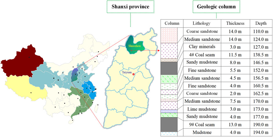
FIGURE 1. Comprehensive geological histogram of the panel B909.
Pingshuo No. 2 Colliery incorporates several preexisting small mines, making it possible for the current longwall workface to be affected by the previous mining activities. These small-scale mines used tunneling to cave coals, leaving many damage zones in Panel B909 area. Also, due to lacking engineering drawings for explicitly indicating the location and geology of damage zones, it is challenging to conduct ultra-thick coal seam mining smoothly. Transient electromagnetic methods and advanced detection were employed to capture the spatial position and dimension of these damage zones. Field observation identified seven damage zones within the designated area of Panel B909, labeled A to G in Figures 2A,B. The seven damage zones cover 173.0 m along the longitudinal direction (longwall retreating direction) and 175.0 m along the transverse direction. The distance between these damage zones and the set-up position of Panel B909 is about 410.0 m.
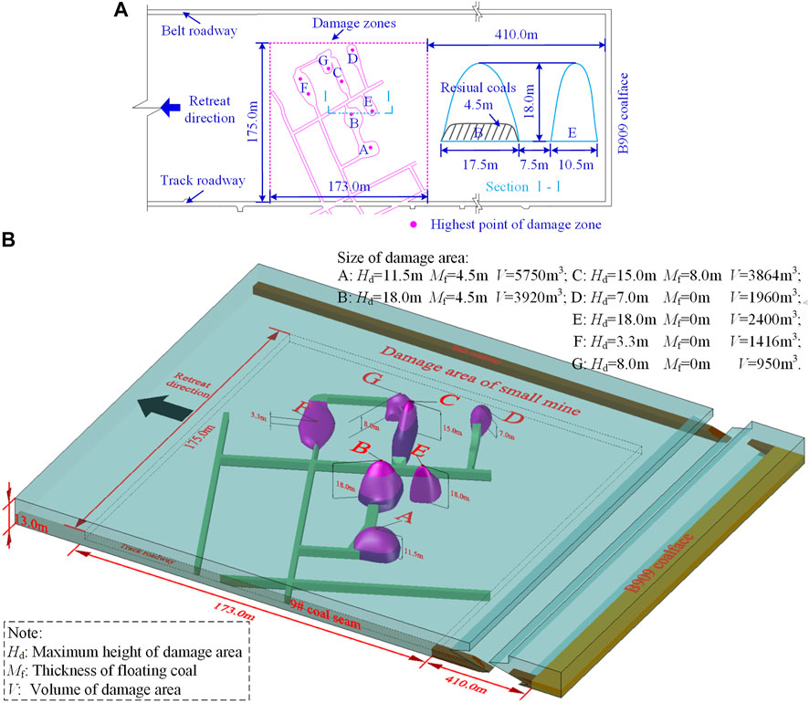
FIGURE 2. Position of seven damage zones with respect to Panel B909: (A) planform; (B) three-dimensional stereogram.
Field detection details show that all the damage zones are of semi-ellipsoidal profiles but different in the maximum height, dimension, and volume of residual coals. According to the geological conditions, the seven damage zones can be divided into three categories, including ① the case without residual coals in damage zones, ② the case where residual coals are thinner than the cutting height, and ③ the case where residual coals are thicker than the cutting height.
Taking damage zones B and E as examples, via the peak of both damage zones, a longitudinal section is made and labeled I-I in Figure 2A. It can be seen from Figure 2 that both damage zones are of a semi-ellipsoidal profile, and the maximum height of both reaches 18.0 m. There are 4.5-m-thick coals left in damage zone B but none in damage zone E. The characteristic parameters of the seven damage zones are shown in Figure 2B.
The damage zones left by the previous small-scale mining activities can delay the routine work of newly scheduled longwall panels. If there are no pre-mining treatments, the damage zones are likely to connect the longwall face and lead to a series of mine hazards, which mainly include the following two aspects.
1) Hydraulic chocks are directly exposed to a high volume of fragmented rocks and are thus less capable of ensuring the safety of workers passing through the face. Within the area that is 20–60 m ahead of the face, hydraulic chocks provide substandard resistance against roof loads, slowing the advancement of the chock itself and the AFC pushed by chocks.
2) As they are filled with fragmented rocks, the damage zones are structurally unstable and prone to collapse due to the mining effect. The caved rocks shock mining equipment and impact their routine operation. Backfilling treatment is an effective tool in optimizing stress distribution and consolidating cracked rock masses in damage zones. Therefore, the damage zones can be filled in advance so that the intact coal body and the coals left by the previous mining activities can be extracted safely.
The coal mining in Panel B909 is expected to achieve the following targets. First, the filling thickness should be greater than the cutting height, and a particular part of the filling body should maintain above hydraulic chocks during cutting. The remaining layer allows hydraulic chocks to receive sufficient reactive force to push AFC forward and protect underlying facilities from caved materials. Second, the lower part of the filling body can be peeled off easily by the shearer so that the cutter teeth can be saved from wear and tear to a great extent.
According to the above analysis, this study proposes the FBRM method, whose essence is that the filling into preexisting damage zones should be performed before longwall panel extraction. The filling materials should not only satisfy the above targets but also consider filling expenditures. For acquiring a robust bearing capacity for the upper layer and satisfactory cuttability for the lower layer, different kinds of functional materials are expected to strengthen the two parts. Material with low strength and good cuttability applies to the lower part, namely, cutting layer filling. In contrast, high strength and strong bearing capacity material is used for the upper part to form a key bearing layer. The layered filling scenario is schematically exhibited in Figure 3.
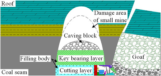
FIGURE 3. Schematic of layered filling for damage zone treatment.
According to the FBRM mechanism, the procedure for the layered filling of damage zones is designed as follows:
1) Conduct precise detection towards the damage zone. The transient electromagnetic method, three-dimensional earthquake, and channel waves can capture key geological parameters, including spatial position, dimension, height, and thickness of residual coals.
2) Apply different filling materials to different layers. The material selection should be according to the designed function of the LCL and UKBL, as analyzed in Section 3.1.
3) Determine the filling thickness of the LCL. Specific filling parameters must be determined according to the relationship between maximum height of damage area (Hd) and cutting height of shearer (Hs). The determination method of filling thickness of the LCL is shown in Table 1.
4) Determine the filling thickness of the UKBL. It should consider the filling material property and rock caving impact and ensure that the UKBL remains intact during mining. The theoretical determination method of the thickness of the UKBL is shown in Table 1.
5) Perform in situ industrial tests, through which the material and filling thickness of the LCL and UKBL can be evaluated by monitoring roadway deformation and hydraulic chock reaction.
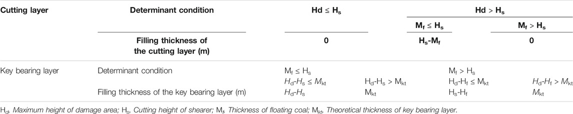
TABLE 1. Determination method of thickness of the cutting layer and key bearing layer.
The critical procedures of the FBRM method are shown in Figure 4.
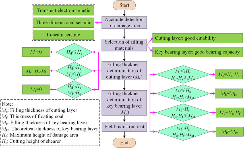
FIGURE 4. Critical procedures for the FBRM method.
As described in section 3.2, the filling thickness determination of the UKBL was the most important step in the FBRM method. The theoretical solution of the filling thickness of the UKBL can be obtained via the mechanical balance principle. The theoretical solution can provide a preliminary reference for the final determination of the filling thickness of the UKBL. Based on this theoretical solution, a numerical model representing the FBRM mechanism is established to acquire the optimal solution of the filling thickness.
The above analysis indicates two circumstances regarding the pre-mining filling of the UKBL when the LCL thickness is fixed. The first circumstance refers to a situation where the distance from the maximum damage height to the filling thickness of the LCL is no greater than the theoretical filling thickness of the UKBL. The area to be cut or the damaged area above residual coals are filled to consolidate fragmented rocks and keep mining safe, as shown in Figure 5A. Figure 5B describes another circumstance where the aforementioned distance is greater than the theoretical filling thickness of the UKBL. In this case, there is an unfilled void existing above, and mining-induced coal/rock caving impacts the underlying rock units and deteriorates the stability of the UKBL. The scenario in Figure 5B is taken as an example to calculate the filling thickness of the UKBL.
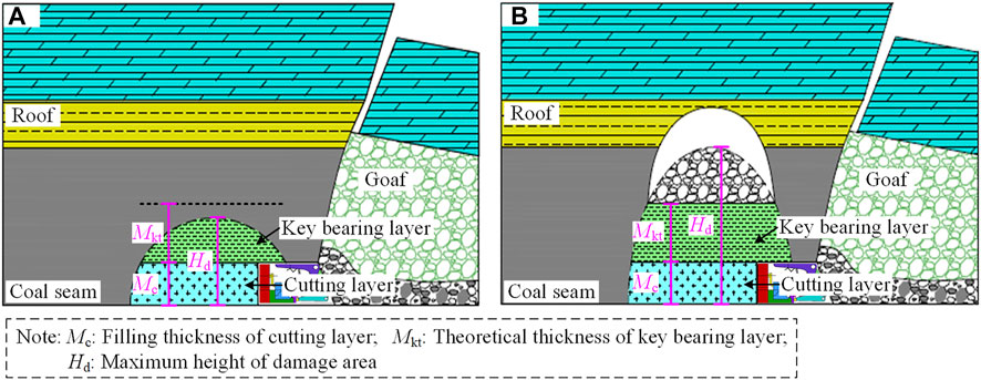
FIGURE 5. Two patterns of damage zone filling: (A) Mkt+Mc ≤ Hd; (B) Mkt+Mc > Hd.
According to the designed longwall operation, two to three hydraulic chocks move together following the shearer, as shown in the close-up view of Figure 6. This operation inevitably causes a particular area of the roof to be suspended, that is, a rectangular support lagging area. As a result, the rocks caving from the top of the support lagging area can directly stress the UKBL and lead to cracking and failure.
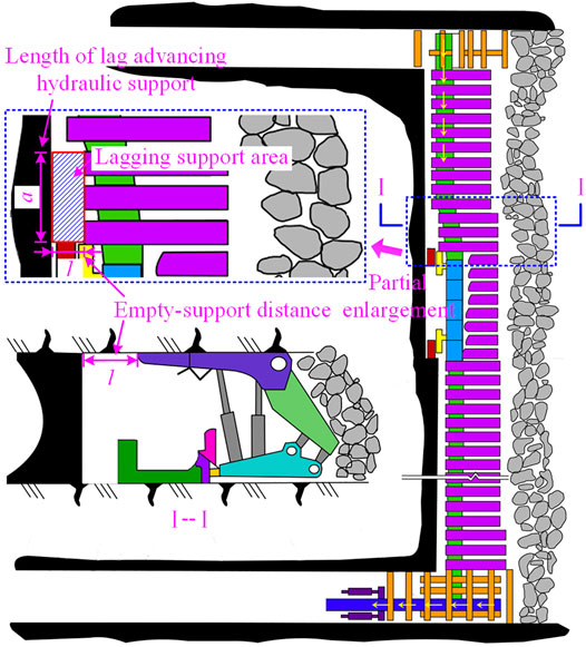
FIGURE 6. Hydraulic chocks moving forward, with a delay relative to the shearer.
It is assumed that the theoretical filling thickness of the UKBL is Mkt, the maximum height of a failure zone is Hd, and the filling thickness of the LCL is Mc. The maximum caving height H of failure zones can be expressed as follows:
The total width of the hydraulic chocks that are delayed in moving is a, and the distance from the delayed chocks to the frontal rib is l. The maximum shock load of overlying rocks caving onto the UKBL is as follows:
where Kd refers to the dynamic factor and equals
Assuming that the UKBL within the support lagging area fails in shear effect, the shear stress of the UKBL is as follows:
In line with Tresca failure criterion (Inoue, 1996; Cai and Wang, 2018), we have the following:
where σs refers to the tensile strength of the filling material of the UKBL.
By incorporating Eqs 1–4, the filling thickness of the UKBL is as follows:
For the UKBL, the filling body is anticipated to bear plastic deformation to alleviate the impact of rock caving on hydraulic chocks. The Remy filling materials from Minova International can meet the requirements mentioned above and generate microbubbles. Hence, two various Remy materials were used to fill the LCL (Label No. 2) and UKBL (Label No. 1). The two materials No. 1 and No. 2 are 1,250 kg/m3 and 600 kg/m3 in density, 1.6 and 1.9 GPa in elastic modulus, and 4.0 and 1.5 MPa in UCS, respectively.
By combining Panel B909 parameters and filling material properties to Eq. 5, the theoretical solution of the filling thickness of the UKBL is determined. Relevant numerical parameters are listed in Table 2, among which the maximum damage height is chosen from all damage zones.
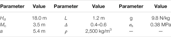
TABLE 2. Parameters for calculating the filling thickness of the key bearing layer.
Applying the parameters in Table 2 to Eq. 5, it is found that the filling thickness of the UKBL (Mkt) equals 4.40–4.88 m.
A numerical model of the over-irregular damage zone was established to determine the optimal filling thickness of the UKBL by comparing mining-induced fracture propagation and maximum principal stress level. The software adopted is Universal Distinct Element Code (UDEC).
Numerical modeling has been extensively applied to address geotechnical issues regarding underground mining, tunneling, and slope movement, requiring an indispensable procedure that parameters for mechanical computation should be calibrated using actual data (Zhang et al., 2021a; 2021b). Existing studies show that uniaxial compression and Brazilian splitting tests are two frequently used methods to verify the property of the rock matrix and joints (Bai et al., 2016; Zhu et al., 2020). The modeled samples subjected to uniaxial compression and Brazilian splitting are exhibited in Figure 7A. The uniaxial compression test uses samples 100 mm in length and 50 mm in diameter, while the Brazilian splitting test uses samples 50 mm in diameter. In constitutive settings, both loading ends are rigid, and the rock matrix and joints are assigned as the elastic and residual strength models, respectively. The loading process is controlled via the rate. More detailed procedures are described in the studies by Singh and Rao (2005) and Kazerani and Zhao (2010). Take the 7.5-m-thick medium sandstone unit (shown in Figure 1) as an example; the simulated compression and tension on samples cored from this layer are exhibited in Figures 7B,C, accompanied by laboratory test results for comparison. The sample failure pattern and stress-strain curve indicate that the calibrated model has a good agreement with laboratory tests, possessing an error of 1.82% in uniaxial compressive strength and 0.32% in tensile strength with respect to the actual experimental data. The results indicate that various physical and mechanical parameters for the 7.5-m-thick medium sandstone stratum have been reliably calibrated. Similarly, numerical models for other rock units are also verified, and the parameters after calibration are summarized in Table 3.
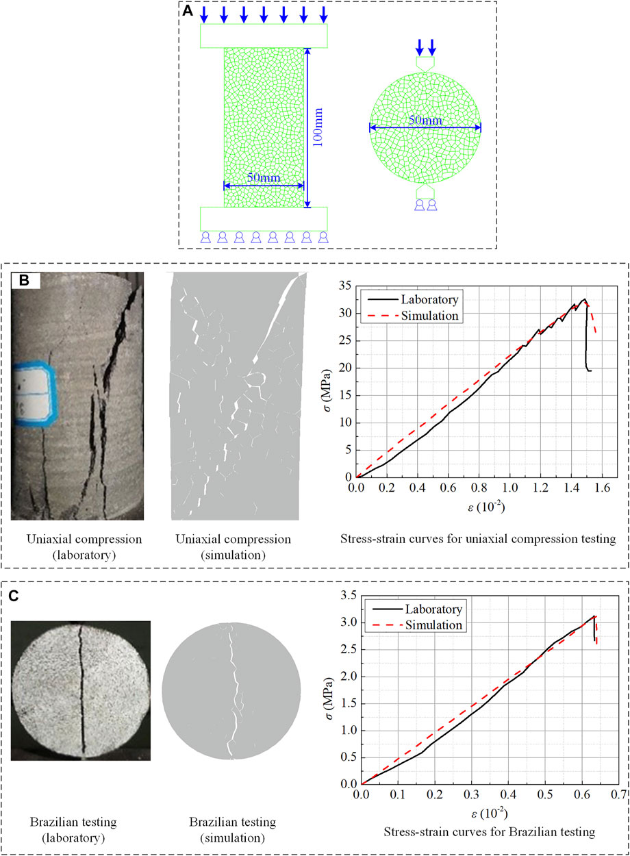
FIGURE 7. Construction and calibration of numerical modeling: (A) model construction; (B) comparison of uniaxial compression; (C) comparison of Brazilian splitting.
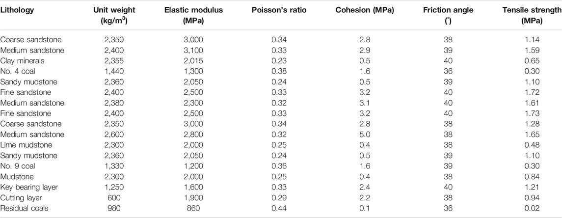
TABLE 3. Numerical simulation calculation parameters.
A large-scale model is then constructed with the geology of Panel B909 as the background, in which the calibrated physical and mechanical parameters are assigned to the corresponding rock units. Field measurement shows that the damage zone reaches its maximum height (18.0 m) in zones B and E. Damage zones B and E are close to each other and located almost along the longitudinal direction (longwall retreating direction), as shown in Figure 2. It can be extrapolated that, as the longwall face progresses, the strata above zones B and E experience more drastic impacts than other zones. Therefore, the large-scale model considers the case where the longwall face successively passes through zones E and B. Figure 8 shows the model incorporating a longwall panel, the overlying strata, and damage zones E and B.
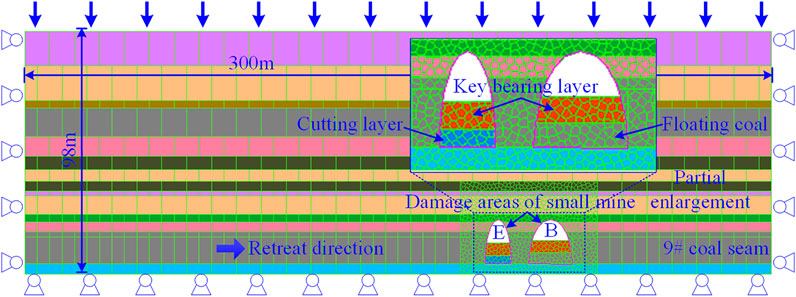
FIGURE 8. Numerical model for analyzing rock mass behavior in response to FBRM.
The geo-mechanical model is 300 m in length and 98 m in height, with the 50-m-long coal body kept unmined for boundaries on both sides. The model is fixed along both sides and the bottom edge via zero velocity, and the top surface is treated as a stress boundary bearing vertical stress of 2.4 MPa. The ratio of horizontal stress to vertical stress is 1.2 throughout the whole profile. Phased excavation is used for simulating actual longwall work, for which the excavation command is executed per 5 m. According to the theoretical filling thickness calculated in Section 4, four scenarios are designed where the filling thickness of the key bearing ranges from 3 to 6 m. Besides, Voronoi meshing is adopted to densify the joints around the two damage zones for detailing rock mass deformation and caving behavior, as shown in Figure 8.
Figure 9 shows four fracture propagation scenarios where the longwall workface is 5 m away from the damage zone E, with filling thickness ranging from 3 to 6 m, as exhibited in Figures 9A–D, respectively. Figure 10 suggests that peak positions of the maximum principal stress are varied under different filling thicknesses of the UKBL.
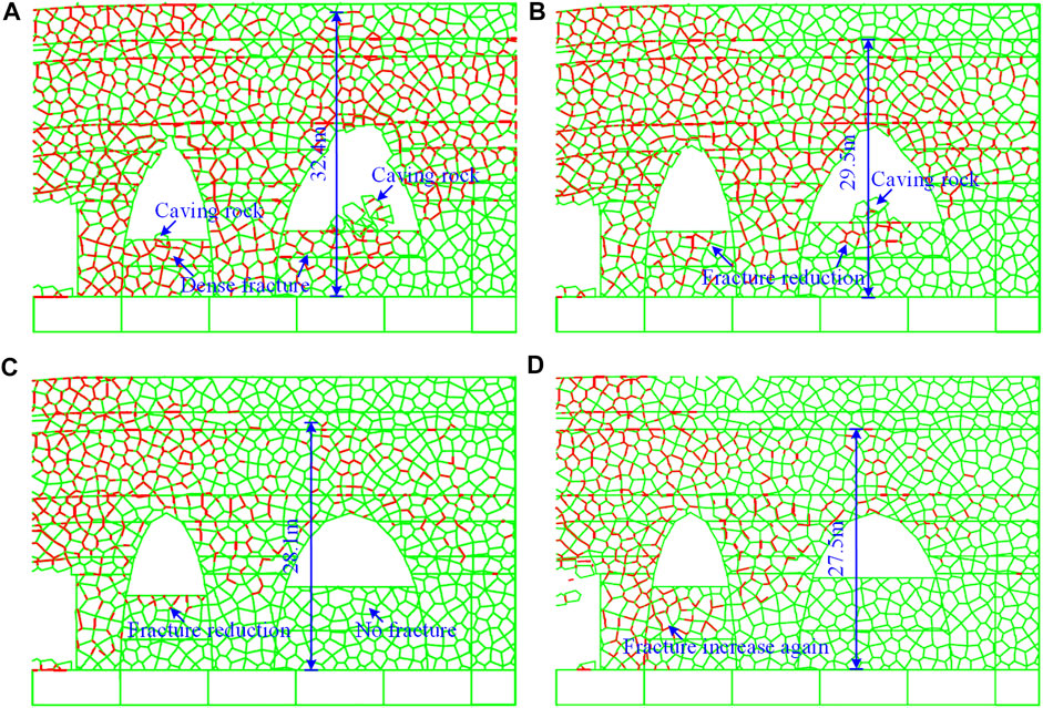
FIGURE 9. Fracture propagation profile: (A) 3 m; (B) 4 m; (C) 5 m; (D) 6 m.
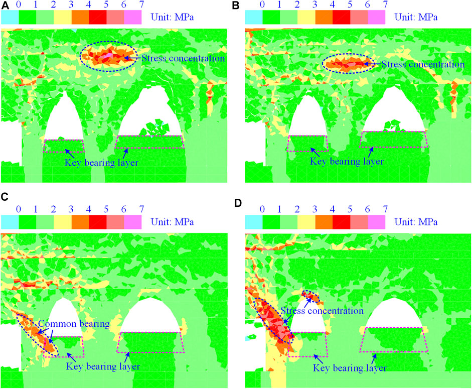
FIGURE 10. Maximum principal stress contour: (A) 3 m; (B) 4 m; (C) 5 m; (D) 6 m.
The comparison between Figures 9A–D indicates that fracture density gradually decreases with increasing filling thickness of the UKBL. When a 3-m-thick area is filled, as shown in Figure 9A, the fractures are extremely dense around the damage zone, and the UKBL in both damage zones lose bearing capacity due to extensive fracturing. Simultaneously, pronounced rock caving occurs along the roof of both damage zones, shocking the underlying key bearing stratum. As the thickness of filling enlarges to 4 m, fractures about damage zones become slightly sparse, especially within the UKBL of damage zone B. The roof of damage zone E cracks but keeps its position, and roof rock cracking and caving are also relieved to some extent, as shown in Figure 9B. With filling thickness further increased to 5 m, fractures become lesser in the UKBL of damage zone E and fade away in damage zone B, and roof rocks remain uncaved in both damage zones, as shown in Figure 9C. Figure 9D shows that when a 6-m-thick area is filled, there is an increase in fracture population, especially within the UKBL of damage zone E, characterizing an increasing trend contrary to previous scenarios. Quantitatively, the distance between the top of continuous fracturing and the coal seam floor exponentially decreases with filling thickness enlarged; the height of fracturing above damage zone B declines from 32.4 to 28.1 m with filling thickness increased from 3 to 5 m. However, the decrease becomes slight if the filling thickness is further enlarged. The relationship between the height of fracturing and filling thickness is depicted in Figure 11.
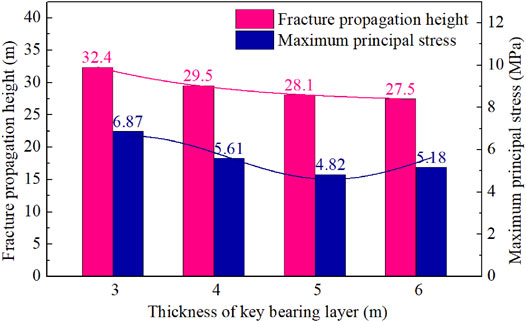
FIGURE 11. Curves of the height of fracturing and the maximum principal stress versus filling thicknesses.
From Figure 10, when the filling thickness is no greater than 4 m, the maximum principal stress reaches its peak value in the area above the pillar between damage zones E and B and forms significant stress concentration, as shown in Figures 10A,B. It can be understood by combing Figures 9A,B that in both filling thicknesses, around damage zones E and B, the fractures drastically propagate, degrading the bearing capacity of surrounding rock masses and causing the peak stress to be transferred to a deep position. When a 5-m-thick area is filled, the maximum principal stress peaks in the frontal abutment, suggesting an adequate bearing capacity of the UKBL, as shown in Figure 10C. In the case of 6-m filling thickness, Figure 10D shows that stress concentration occurs in front of the workface and along the roof of damage zone E. The maximum principal stress shows a decrease–increase trend with filling thickness enlarged, as depicted in Figure 11.
The above analysis indicates that when the filling thickness is 5 m, the UKBL slightly cracks, and rock masses surrounding damage zones E and B remain stable. The maximum principal stress reaches the lowest level by adopting this filling thickness, and the UKBL shows good bearing capacity. Therefore, the optimal filling thickness of the UKBL is 5 m.
To verify the proposed FBRM method and appropriateness of technical parameters, in situ industrial tests were performed in Panel B909. Before longwall mining, each damage zone was treated with layered filling via grouting holes from belt and track roadways. Four monitoring points were placed along both roadways and corresponding to the top caving position of damage zones B and E for recording bedding plane separation, as shown in Figure 12A. The deep and shallow ends of the monitoring instrument were fixed to the middle of the overlying medium sandstone unit (basic roof) and sandy mudstone unit (immediate roof). In addition, the working resistance of the No. 54 hydraulic chock was continuously recorded to reflect roof pressure response to the filling-based longwall mining. Figures 12B,C show the records of bedding plane separation and resistance of hydraulic chocks.
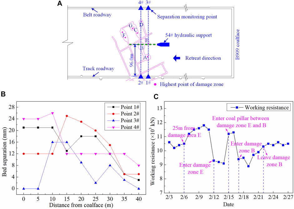
FIGURE 12. Location of monitoring points and field measurement results: (A) location of monitoring points relative to Panel B909; (B) bedding plane separation; (C) working resistance of hydraulic chocks.
Figure 12B shows that with the workface approaching, bedding plane separation experienced a general increase–decrease trend. The separation phenomenon started to occur as the workface was 40 m away from monitoring points. No. 4 point recorded the maximum separation level reaching 26 mm, reflecting the stability and slight deformation of the roadway. Figure 12C shows that when the working face passed through damage zones E and B, the maximum working resistance was 11,800 kN, still lower than the rated level (12,000 kN). The working resistance started to increase as the face was 25 m away from damage zone E, dramatically decreased to 9,100 kN as the coalface entered damage zone E, and then increased again beneath the pillar between damage zones E and B. Similar fluctuation of working resistance repeated when the workface walked through damage zone B. The average working resistance of No. 52 hydraulic chock was 10,400 kN, reflecting a steady state throughout the repeated mining process. Also, roof caving and hydraulic chock failure did not occur. It means that the FBRM method developed in this study and the corresponding filling parameters are reasonable and reliable.
Pre-filling the irregular damage zone is an effective method for preventing roof caving disasters and improving the recovery ratio of ultra-thick coal deposits. Taking Panel B909 of Pingshuo No. 2 Colliery as the case, this study proposed a damage zone filling–based repeated mining method and detailed its procedures. A novel calculation method was developed to preliminarily determine the filling thickness of UKBL. By establishing a numerical model incorporating over-irregular damage zones and longwall mining, fracture propagation and the maximum principal stress profiles in the vicinity of damage zones were evaluated. In situ tests were performed to verify the reliability of the FBRM method. Conclusions are drawn as follows:
1) Pre-mining filling is an effective tool to strengthen the damage zone left by previous mining activities. The filling-based mining should guarantee that 1) the upper filling body has robust bearing capacity to provide sufficient reactive force for hydraulic chocks and to proof mining equipment from being impacted by caving rocks and 2) the lower filling body is of satisfactory cuttability so that cutter teeth can be saved to a great extent.
2) With enlarging the UKBL filling thickness, the fracture propagation height decreases, obeying a negative exponential function. The maximum principal stress shifts from the area above damage zones downward to the frontal abutment as the filling thickness is beyond 5 m, indicating a filling thickness threshold of 5 m where the roof can be stabilized in repeated mining.
3) The optimal filling thickness of the UKBL was determined to be 5 m by comprising the results of numerical simulation and theoretical calculation. In situ tests show that when the workface passed through damage zones B and E, the maximum working resistance of hydraulic chocks was 11,800 kN (12,000 kN in rated resistance), and the roof separation was 26 mm. The results suggest that the FBRM method is reliable and effective in addressing the pre-existing damage zones, thus providing best-practice references for retrieving the coals left by previous mining activities with roof caving hazards minimized.
The original contributions presented in the study are included in the article; further inquiries can be directed to the corresponding author.
LC: formal analysis; writing—original draft. DZ and GF: conceptualization; methodology. SZ: data curation; numerical calculation. XW and WZ: design of the experiment; editing. All authors contributed to manuscript revision and read and approved the submitted version.
This study is supported by the National Natural Science Foundation of China (Nos. 52104100 and 51874278), the China Postdoctoral Science Foundation (No. 2021M703503), the open-ended fund of Hubei Key Laboratory for Efficient Utilization and Agglomeration of Metallurgic Mineral Resources (No. 2020zy002), and the Independent Research Project of State Key Laboratory of Coal Resources and Safe Mining (No. SKLCRSM 2020X04).
The authors declare that the research was conducted in the absence of any commercial or financial relationships that could be construed as a potential conflict of interest.
All claims expressed in this article are solely those of the authors and do not necessarily represent those of their affiliated organizations, or those of the publisher, the editors, and the reviewers. Any product that may be evaluated in this article, or claim that may be made by its manufacturer, is not guaranteed or endorsed by the publisher.
Bai, Q.-S., Tu, S.-H., Zhang, C., and Zhu, D. (2016). Discrete Element Modeling of Progressive Failure in a Wide Coal Roadway from Water-Rich Roofs. Int. J. Coal Geology. 167, 215–229. doi:10.1016/j.coal.2016.10.010
Benzaazoua, M., Belem, T., and Bussière, B. (2002). Chemical Factors that Influence the Performance of Mine Sulphidic Paste Backfill. Cement Concrete Res. 32, 1133–1144. doi:10.1016/s0008-8846(02)00752-4
Benzaazoua, M., Fall, M., and Belem, T. (2004). A Contribution to Understanding the Hardening Process of Cemented Pastefill. Minerals Eng. 17, 141–152. doi:10.1016/j.mineng.2003.10.022
Cai, S.-P., and Wang, Z.-J. (2018). An Analytical Solution of Eccentric Transverse Deflection in Rigid-Plastic Solids. Int. J. Mech. Sci. 145, 188–199. doi:10.1016/j.ijmecsci.2018.06.013
Chang, Q., Chen, J., Zhou, H., and Bai, J. (2014). Implementation of Paste Backfill Mining Technology in Chinese Coal Mines. Scientific World J. 2014, 1–8. doi:10.1155/2014/821025
Deng, D. Q., Jiang, N., and Duan, Y. (2021). Sampling and Mechanical Testing of Backfill in Large Mined-Out Area. Geofluids 2021, 1–8. doi:10.1155/2021/6686385
Edraki, M., Baumgartl, T., Manlapig, E., Bradshaw, D., Franks, D. M., and Moran, C. J. (2014). Designing Mine Tailings for Better Environmental, Social and Economic Outcomes: A Review of Alternative Approaches. J. Clean. Prod. 84, 411–420. doi:10.1016/j.jclepro.2014.04.079
Farhad Howladar, M., and Mostafijul Karim, M. (2015). The Selection of Backfill Materials for Barapukuria Underground Coal Mine, Dinajpur, Bangladesh: Insight from the Assessments of Engineering Properties of Some Selective Materials. Environ. Earth Sci. 73, 6153–6165. doi:10.1007/s12665-014-3841-1
Hefni, M., Ahmed, H. A. M., Omar, E. S., and Ali, M. A. (2021). The Potential Re-use of Saudi Mine Tailings in Mine Backfill: A Path towards Sustainable Mining in saudi arabia. Sustainability 13, 6204. doi:10.3390/su13116204
Helinski, M., Fahey, M., and Fourie, A. (2010). Coupled Two-Dimensional Finite Element Modelling of Mine Backfilling with Cemented Tailings. Can. Geotech. J. 47, 1187–1200. doi:10.1139/T10-020
Inoue, T. (1996). Analysis of Plastic Buckling of Steel Plates in Shear Based on the Tresca Yield Criterion. Int. J. Sol. Structures 33, 3903–3923. doi:10.1016/0020-7683(95)00222-7
Jixiong Zhang, J., Sun, Q., Zhou, N., Haiqiang, J., Germain, D., and Abro, S. (2016). Research and Application of Roadway Backfill Coal Mining Technology in Western Coal Mining Area. Arab. J. Geosci. 9, 1–10. doi:10.1007/s12517-016-2585-5
Kazerani, T., and Zhao, J. (2010). Micromechanical Parameters in Bonded Particle Method for Modelling of Brittle Material Failure. Int. J. Numer. Anal. Meth. Geomech. 34, 1877–1895. doi:10.1002/nag.884
Kostecki, T., and Spearing, A. J. S. (2015). Influence of Backfill on Coal Pillar Strength and Floor Bearing Capacity in Weak Floor Conditions in the Illinois Basin. Int. J. Rock Mech. Mining Sci. 76, 55–67. doi:10.1016/j.ijrmms.2014.11.011
Li, M., Li, A., Zhang, J., Huang, Y., and Li, J. (2020). Effects of Particle Sizes on Compressive Deformation and Particle Breakage of Gangue Used for Coal Mine Goaf Backfill. Powder Tech. 360, 493–502. doi:10.1016/j.powtec.2019.10.075
Ma, Z., Fan, J., Sun, K., Zhao, G., and Pan, Y. (2011). Study on Stope Stability during Repeated Mining with Fully-Mechanized Solid Filling Technology in Residual Coal Pillar Area. J. Min. Saf. Eng. 28, 499–504. doi:10.3969/j.issn.1673-3363.2011.04.001
Mitchell, R. J., Olsen, R. S., and Smith, J. D. (1982). Model Studies on Cemented Tailings Used in Mine Backfill. Can. Geotech. J. 19, 14–28. doi:10.1139/t82-002
Nujaim, M., Belem, T., and Giraud, A. (2020). Experimental Tests on a Small-Scale Model of a Mine Stope to Study the Behavior of Waste Rock Barricades during Backfilling. Minerals 10, 941. doi:10.3390/min10110941
Sasa, Z., Gaofeng, R., Xinping, L., Yujie, W., and Ashraf, M. A. (2019). Proportion Optimization of Cemented Tailing Backfill and its Interaction Mechanism with Rocks in Room-And-Pillar Stope: A Case Study. Int. J. Electr. Eng. Edu. 1, 002072091984420. doi:10.1177/0020720919844208
Seryakov, V. M. (2014). Mathematical Modeling of Stress-Strain State in Rock Mass during Mining with Backfill. J. Min. Sci. 50, 847–854. doi:10.1134/S1062739114050044
Shi, X. (2013). China's Small Coal Mine Policy in the 2000s: A Case Study of Trusteeship and Consolidation. Resour. Pol. 38, 598–604. doi:10.1016/j.resourpol.2013.09.009
Singh, M., and Seshagiri Rao, K. (2005). Empirical Methods to Estimate the Strength of Jointed Rock Masses. Eng. Geology. 77, 127–137. doi:10.1016/j.enggeo.2004.09.001
Sivakugan, N., Veenstra, R., and Naguleswaran, N. (2015). Underground Mine Backfilling in Australia Using Paste Fills and Hydraulic Fills. Int. J. Geosynth. Ground Eng. 1, 18. doi:10.1007/s40891-015-0020-8
Tapsiev, A. P., Freidin, A. M., Filippov, P. A., Neverov, A. A., Neverov, S. A., Artemenko, Y. V., et al. (2011). Extraction of Gold-Bearing Ore from under the Open Pit Bottom at the Makmal deposit by Room-And-Pillar Mining with Backfill Made of Production Waste. J. Min. Sci. 47, 324–329. doi:10.1134/s1062739147030099
Walske, M. L., McWilliam, H., Doherty, J., and Fourie, A. (2016). Influence of Curing Temperature and Stress Conditions on Mechanical Properties of Cementing Paste Backfillfluence of Curing Temperature and Stress Conditions on Mechanical Properties of Cementing Paste Backfill. Can. Geotech. J. 53, 148–161. doi:10.1139/cgj-2014-0502
Wang, X., and Weng, M. (2012). Prediction and Backfill Mining Technology of Ultra Thick Seam in Goaf of Small Mine. Coal Sci. Technol. 40, 41–44. doi:10.13199/j.cst.2012.10.47.wangx.019
Wu, J., and Xu, J. (2012). Key Technology for Fully Mechanized Top Coal Caving Mining in Thick Seam Passing through Small Mine Goaf with Backfill. Coal Sci. Technol. 40, 30–33. doi:10.13199/j.cst.2012.04.35.wujn.013
Xu, W., Cao, P., and Tian, M. (2018). Strength Development and Microstructure Evolution of Cemented Tailings Backfill Containing Different Binder Types and Contents. Minerals 8, 167. doi:10.3390/min8040167
Yu, Y., Ma, L., and Zhang, D. (2019). Characteristics of Roof Ground Subsidence while Applying a Continuous Excavation Continuous Backfill Method in Longwall Mining. Energies 13, 95. doi:10.3390/en13010095
Yujiang Zhang, Y., Feng, G., Zhang, M., Ren, H., Bai, J., Guo, Y., et al. (2016). Residual Coal Exploitation and its Impact on Sustainable Development of the Coal Industry in China. Energy Policy 96, 534–541. doi:10.1016/j.enpol.2016.06.033
Zhang, Y., Cao, S., Guo, S., Wan, T., and Wang, J. (2018). Mechanisms of the Development of Water-Conducting Fracture Zone in Overlying Strata during Shortwall Block Backfill Mining: A Case Study in Northwestern China. Environ. Earth Sci. 77, 1–17. doi:10.1007/s12665-018-7726-6
Zhang, S., Fan, G., Jiang, S., Fan, Z., Li, S., and Ni, H. (2021a). Dual-hazard Control Mechanism of Burst-Prone and Spontaneous Combustion Coalface Considering Effect of Retreat Speed. Energ. Rep. 7, 278–288. doi:10.1016/j.egyr.2020.12.033
Zhang, S., Fan, G., Zhang, D., Li, S., Chen, M., Fan, Y., et al. (2021b). Impacts of Longwall Mining Speeds on Permeability of Weakly Cemented Strata and Subsurface Watertable: a Case Study. Geomatics, Nat. Hazards Risk 12, 3063–3088. doi:10.1080/19475705.2021.1993354
Zhou, N., Zhang, J., Yan, H., and Li, M. (2017). Deformation Behavior of Hard Roofs in Solid Backfill Coal Mining Using Physical Models. Energies 10, 557. doi:10.3390/en10040557
Keywords: ultra-thick coal seam, damage zones, filling-based repeated mining, lower cutting layer, key bearing layer
Citation: Chen L, Zhang D, Fan G, Zhang S, Wang X and Zhang W (2022) A New Repeated Mining Method With Preexisting Damage Zones Filled for Ultra-Thick Coal Seam Extraction – Case Study. Front. Earth Sci. 10:835867. doi: 10.3389/feart.2022.835867
Received: 15 December 2021; Accepted: 04 February 2022;
Published: 23 February 2022.
Edited by:
Wei Liu, Chongqing University, ChinaReviewed by:
Huafu Qiu, Xi’an University of Science and Technology, ChinaCopyright © 2022 Chen, Zhang, Fan, Zhang, Wang and Zhang. This is an open-access article distributed under the terms of the Creative Commons Attribution License (CC BY). The use, distribution or reproduction in other forums is permitted, provided the original author(s) and the copyright owner(s) are credited and that the original publication in this journal is cited, in accordance with accepted academic practice. No use, distribution or reproduction is permitted which does not comply with these terms.
*Correspondence: Shizhong Zhang, emhhbmdzaGl6aG9uZ0BjdW10LmVkdS5jbg==
Disclaimer: All claims expressed in this article are solely those of the authors and do not necessarily represent those of their affiliated organizations, or those of the publisher, the editors and the reviewers. Any product that may be evaluated in this article or claim that may be made by its manufacturer is not guaranteed or endorsed by the publisher.
Research integrity at Frontiers
Learn more about the work of our research integrity team to safeguard the quality of each article we publish.