 Hongwu Lei
- State Key Laboratory of Geomechanics and Geotechnical Engineering, Institute of Rock and Soil Mechanics, Chinese Academy of Sciences, Wuhan, China
CO2 is considered as a novel heat-transmission fluid for extracting geothermal energy from enhanced geothermal systems (EGS), attributed to its high compressibility, expansivity and low viscosity in comparison to water. In order to compare the performance of CO2 and H2O as the working fluid in EGS, a classical five-spot model based on the geologic and geothermal conditions at the Songliao Basin, China, was constructed. Results obtained from the coupled wellbore/reservoir model revealed that the net heat extraction and flow rate are greater for CO2 than for H2O at a fixed operation pressure difference between the injection and production wellheads. However, the wellhead temperature is far lower for CO2 than for H2O due to the strong Joule–Thomson effect of CO2 in the wellbore. Moreover, a stronger pressure change in the wellbore is observed by using CO2, attributed to the gravity and high flow velocity of CO2; this pressure change induces a drop in the frictional pressure. For CO2, the enthalpy change in the wellbore is mainly contributed by the gravitational potential, while for H2O, it is contributed by the gravitational potential and lateral heat exchange. The heat extraction performance depends on the operation pressure difference and injection temperature for H2O-based EGS, while it depends on the wellhead pressures of both the injection and production wells as well as the injection temperature for CO2-based EGS. A high operation pressure is favorable for improving the heat extraction performance (especially the production temperature) for CO2. With the temperature drop limitation at the downhole of the production well, the heat extraction performance is better by using H2O than that by using CO2 as the working fluid. However, the low-power consumption for maintaining fluid circulation demonstrates the application potential of CO2-based EGS.
1 Introduction
Geological sequestration of carbon dioxide (CO2) in geological formations has been recognized as a technically feasible method to control or slow down the climate change trend (White et al., 2003; Orr, 2004; Metz et al., 2005; Goodman et al., 2013; IPCC 2014). It is recently considered as a novel heat-transmission fluid instead of H2O for extracting geothermal energy from EGS, which can simultaneously achieve energy extraction and CO2 geological sequestration (Brown D., 2000; Mohan et al., 2013; Xu R. et al., 2015; Pan F. et al., 2017; Wang et al., 2018; Shi et al., 2018; Bongole et al., 2019; Singh et al., 2020; Cui et al., 2021). CO2 could perform better than H2O, because of 1) large buoyancy force caused by a density difference between cold and hot CO2, leading to the natural thermosiphon; 2) strong mobility, which can yield large flow velocities for a given pressure gradient; 3) low reactivity, which reduces or eliminates scaling problems caused by the water-rock geochemical reaction (Brown, 2000).
Although there is no commercial project with CO2 as the working fluid for extracting deep geothermal energy, a number of numerical simulations were conducted to examine the feasibility and heat mining performance. Pruess (2006) used TOUGH2 to simulate the heat extraction performance of CO2-based EGS and demonstrated that the mass flows and net heat extraction rate generated by CO2 are higher than that generated by H2O, by four times and 50%, respectively. Furthermore, Pruess (2008) conducted three-dimensional simulations to investigate the production behavior and revealed that production wells should be open only in a limited vertical interval near the reservoir top to avoid thermal breakthrough due to the large contrast in the CO2 density. To consider fluid flow and heat transfer in wellbores, Atrens et al. (2010) conducted a simple calculation with pipe flow and the first law of thermodynamics for wellbores and a lumped-parameters model for reservoirs and showed that compared to water, CO2 is less effective for extracting energy under conditions similar to those utilized for past EGS trials (Murphy et al., 1999). Following the same calculation method, Zhang et al. (2013) compared the thermodynamic performance for CO2-based EGS and H2O-based EGS systems, indicating that CO2-based EGS produces more power in reservoirs with a low recoverable thermal energy, and operation parameters should be optimized to match the actual CO2-based EGS condition. Recently, the calculation for the effect of impurities on CO2-based EGS revealed that the system efficiency decreases with the increase in the impurity fractions (Zhang et al., 2016).
To simultaneously consider fluid flow and heat transfer in wellbores and reservoirs, T2Well (Pan et al., 2011; Pan and Oldenburg 2014) was developed and used to evaluate the heat and flow in wells for CO2-based EGS; the results revealed that an appropriate CO2 flow rate is required to generate a positive electric power output for a fixed flow-rate production. Xu et al., 2015b used T2Well to numerically identify advantages and disadvantages of using CO2 as the working fluid and revealed that a very low-temperature fluid was obtained by CO2, which is major disadvantage for CO2-based EGS. Luo et al. (2014) investigated dramatic variations in the supercritical CO2 properties and thermal-hydraulic turbulence features of CO2 in the wellbores in a doublet CO2-EGS system based on conditions at the European EGS site at Groβ Schönebeck using the CFD code FLUENT 6.3. The result demonstrated that a CO2 injection rate of 10 kg/s is apparently favorable for an expected geothermal utilization lifetime of 20 years Huang et al. (2014) coupled the reservoir simulator TOUGH2 (Pruess et al., 1999) with the wellbore simulator HOLA (Aunzo et al., 2011) to evaluate the potential heat extraction using H2O in the Songliao Basin.
In this study, a classical five-spot model based on the geological and geothermal conditions of the Songliao Basin is constructed. The coupled wellbore/reservoir simulator T2Well (Pan et al., 2011; Pan and Oldenburg 2014) is employed to simulate the fully coupled thermal and hydrodynamic (TH) processes. The comparison of the performance, including net heat extraction, flow rate, and production temperature as well as the TH processes in the wellbores and reservoir between H2O-based and CO2-based EGS is performed. Then, sensitivity analysis to the operation parameters, including pressures of injection and production wellheads and injection temperature, is examined. Finally, the optimum results for both H2O-based and CO2-based EGS with the temperature drop limitation at the downhole of production well for the project lifetime are compared. The novelty of this study lies in that 1) the coupling TH processes in wellbore/reservoir system is considered and 2) the performance from the optimum results for both H2O-based and CO2-based EGS is compared.
2 Model Setup
2.1 Geological Setting of the Songliao Basin
The Songliao Basin, located in northeastern China, is a Mesozoic to Cenozoic continental sedimentary rhombic basin, with a length of 750 km and a width of 330–370 km. The total area of the basin is 260,000 km2, comprising six primary structural units including the north plunge zone, west slope zone, northeast uplift zone, central depression zone, southeast uplift zone, and southeast uplift zone, respectively (Figure 1A). The basin was formed by rifting during the late Jurassic, and it was filled by 10-km-thick sediments. The stratigraphic sequence of the basin is dominated by Mesozoic and Cenozoic strata from the Late Jurassic to the Quaternary. The deep formations (buried depth > 2 km) of the basin include the Quantou Formation (K1q), the Denglouku Formation (K1d), the Yingcheng Formation (K1yc), the Shahezi Formation (K1sh), and the Huoshiling Formation (J3h) (Figure 1B). These deep formations are generally composed of sandstone, shale, siltstone, and volcanic and volcaniclastic rocks. The Songliao Basin is regarded as one of the most potential sites for EGS resource exploration, according to the heat flow and depth–temperature datasets (Jiang et al., 2016).
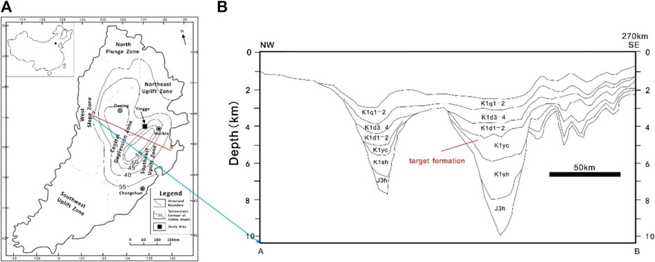
FIGURE 1. (A) Location map of the potential EGS site in the Songliao Basin (China) and (B) Stratigraphic profiles near the study area.
The average geothermal gradient of the basin is ∼3.7°C/100 m, which is one of the highest geothermal gradients among the Chinese basins. According to the MIT report on the definition of an enhanced geothermal system (EGS) (MIT, 2006), the potential depth for geothermal exploitation is between 3 and 6 km, and the acceptable temperature for EGS development is greater than 150°C. Therefore, the formations of K1yc, K1sh, and J3h are the potential candidates for EGS. The formation of K1yc in Shuangcheng Fault Depression, northeast of the central depression zone as the target formation, was selected; it is considered as the most potential site for EGS previously (Huang et al., 2014).
2.2 Simulation Tool
The injection and production wells play key roles in the transportation of the fluid and heat in the reservoir. Temperature and pressure would drastically vary in the wellbores, especially by using CO2 as the working fluid (Atrens et al., 2010). In this study, the integrated wellbore-reservoir simulator T2Well (Pan et al., 2011; Pan and Oldenburg 2014) is employed to compare the fluid flow and heat transfer in the coupled wellbore/reservoir system with CO2 and H2O as working fluids. The governing equations are listed in Table 1. T2Well introduces a special wellbore sub-domain into the numerical grid, thereby extending the current numerical reservoir simulator TOUGH2 to simultaneously and efficiently calculate the flow in the wellbore and reservoir (Pan and Oldenburg 2014). This software is successfully employed to simulate the non-isothermal multiphase, multicomponent flow process in coupled wellbore/reservoir systems for CO2 geological sequestration and geothermal extraction (Hu et al., 2012; Li et al., 2015; Pan et al., 2015; Rasmusson et al., 2015). The module ECO2N V2.0 (Pan L. et al., 2017) that can describe fluid property of CO2-H2O-NaCl systems within temperatures of up to 300°C is incorporated into T2Well for this study.
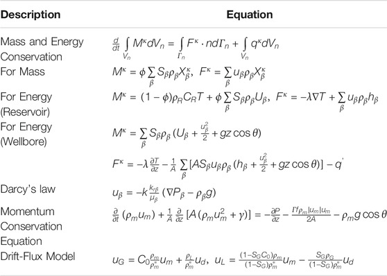
TABLE 1. The governing equations solved in T2Well (Pan and Oldenburg, 2014).
2.3 Model Description
The target reservoir is located at a depth of 3800 m with a thickness of 136 m. To improve heat production, hydro-fracturing is implemented to enhance permeability in this deep granite reservoir. Therefore, the target reservoir is considered as fractured media. A model composed by the target reservoir and injection and production wellbores (Figure 2A) is employed to capture the fluid flow and heat-transfer process in the entire wellbore/reservoir system. For comparing the heat-extraction capability of two heat-transmission fluids, the classic “five-spot” well pattern is employed. The reservoir model can be simplified to a 1/8 symmetry domain due to the symmetry, which can significantly reduce the computational burden. The wells are located at two vertices of the triangle simulation zone, with a distance of 707 m (Figure 2B).
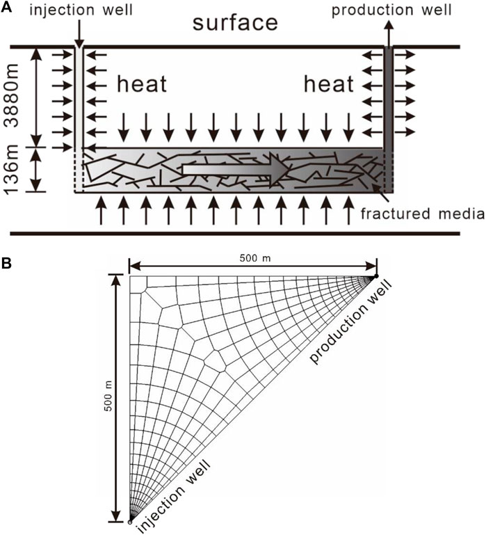
FIGURE 2. (A) Conceptual model for the heat extraction from EGS and (B) grid partition of the reservoir.
To simulate fluid flow and heat transfer in fractures and in the matrix pores, the dual-porosity multiple interacting continua (MINC) (Pruess and Narasimhan, 1982; Pruess and Narasimhan, 1985) model is employed. First, one-layer 2D irregular grids are created to represent the reservoir (Figure 2B). The grid size increases from 0.1 m near the well to 50 m outside. Second, the primary grids are partitioned into five sub-grids by using a set of volume fractions. The injection and production wells fully perforate the reservoir and extend 3,880 m up to the surface. Two 1D vertical grids comprising seventy-eight 50-m grid blocks are created for the wellbores, which are attached to the 2D reservoir grids to represent the injection and production wells.
The reservoir is assumed to be initially saturated with CO2 or H2O. The reservoir temperature is set to 150°C, and its pressure is ∼37.5 MPa according to the calculation with a geothermal gradient of 37°C/km and a hydrostatic pressure distribution. The model also considers the heat exchange between the fluid and the surrounding rock in the wellbore. Table 2 lists the parameters used in the model.
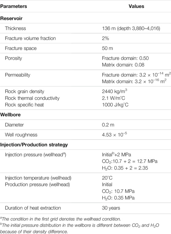
TABLE 2. Parameters for the five-spot heat extraction problem in enhanced geothermal systems.
3 Results and Discussion
3.1 Base Case
Figure 3 shows the temperature, flow rate and net heat extraction rate in the H2O-based and CO2-based EGS, respectively. In the H2O-based EGS, the fluid production rate and temperature are maintained at ∼20 kg/s and 135°C, respectively (Figure 3A). The net heat extraction rate (calculated by
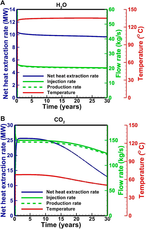
FIGURE 3. Key performance parameters for (A) the H2O-based and (B) CO2-based EGS from simulations.
In the H2O-based EGS, downhole pressures are maintained at 40.6 and 36.0 MPa in the injection and production wells, respectively (Figure 4A). The downhole temperatures are maintained at 33 and 150°C in the injection and production wells, respectively (Figure 4A). On the other hand, in CO2-based EGS, the downhole pressures and temperatures in the production well are stable for the first 10 years, followed by an increase from 36.6 to 38.9 MPa and a decrease from ∼150 to 106°C, respectively. The downhole temperature in the injection well is stabilized at 48°C, but the pressure increases from 44.0 to 45.3 MPa. These fluctuations correspond to the change in flow rate. The downhole pressure in the injection well is determined by the flow process in the wellbore under a fixed wellhead pressure. The decrease in the flow rate results in a pressure loss related to the wellbore roughness. Pressure and temperature distributions satisfy the relative stable condition after a fluid injection of 0.03–0.04 years (Figure 5). In this short period, the downhole pressure in the injection well for the H2O-based EGS increases from 37.5 to 40.6 MPa, while the pressure increases to 44.0 MPa for the CO2-based EGS. There are about 1.1 and 4.5 MPa contributed by the change in density from the wellbore for the H2O-based and CO2-based EGS, respectively. This result is related to the fact that the density of CO2 is more sensitive to temperature. In the production well, the average fluid temperature generally increases due to the upward flow of the hot fluid from the reservoir. The downhole pressures decrease by 1.5 and 0.9 MPa at the start of production for the H2O-based and CO2-based EGS, respectively. This is because that the temperature redistribution in the production well results in a decrease in density. With the heat in the reservoir is gradually extracted, and the fluid temperature in the production wellbore decreases for the CO2-based EGS, thereby increasing the pressure (Figure 5).
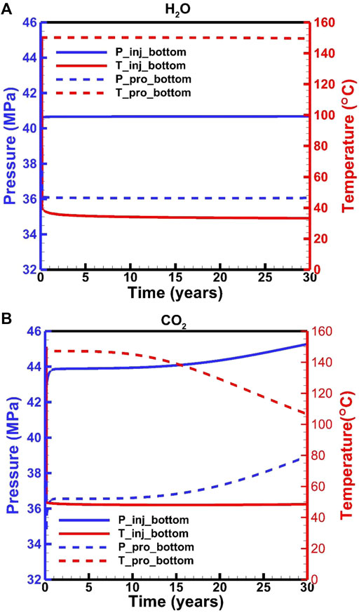
FIGURE 4. Downhole pressure and temperature for (A) the H2O-based and (B) CO2-based EGS.
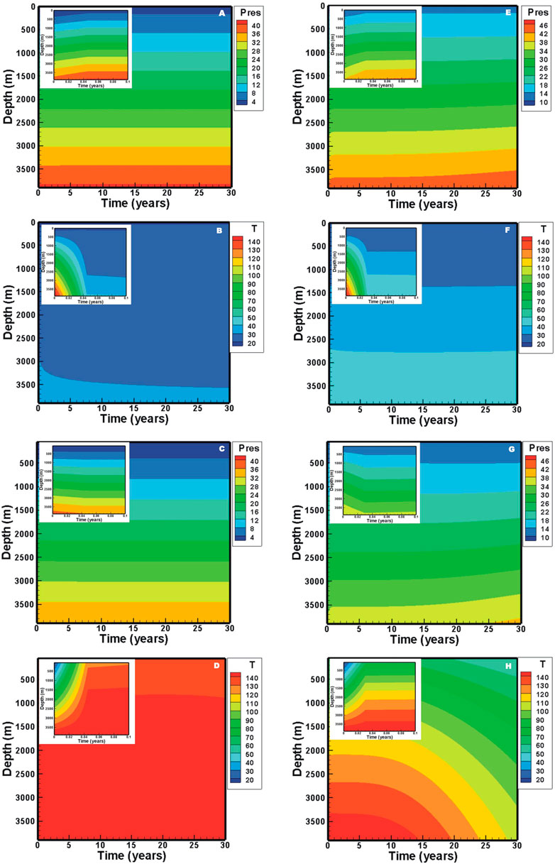
FIGURE 5. Evolution of pressure and temperature distributions in the wellbore: (A) pressure and (B) temperature for H2O in the injection well, (C) pressure and (D) temperature for H2O in the production well, (E) pressure and (F) temperature for CO2 in the injection well, (G) pressure and (H) temperature for CO2 in the production well.
Fluid pressure profiles (Figure 6) reveal that strong pressure gradients are observed near the injection well. The pressure in the reservoir for the CO2-based EGS increases with the production due to the decrease in temperature, thereby increasing the pressure at the downhole of the production well. Finally, the decrease in temperature and increase in pressure lead to a decrease in the flow rate and net heat extraction rate (Figure 3B). The temperature-decrease zone extends to ∼230 m after the production of 5 years for the H2O-based EGS (Figure 6A), while it extends to ∼300 m for the CO2-based EGS (Figure 6B). After the production of 30 years, they extend to 660 m (Figure 6A) for H2O and the production well for CO2 (Figure 6B), and the downhole temperature in the production well decreases to 100°C for CO2 (Figure 6B). Heat extraction within a zone of 180 m away from the injection well is completed after the production of 30 years for the H2O-based EGS (Figure 6A), while the zone reaches to ∼260 m for the CO2-based EGS (Figure 6B).
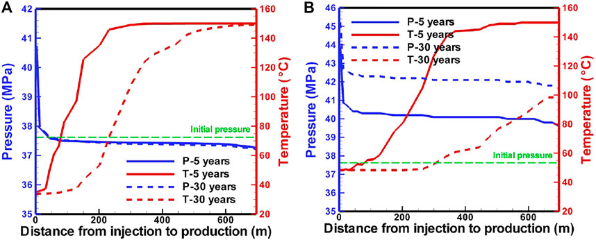
FIGURE 6. Pressure and temperature profiles along a line from the injection well to the production well in the reservoir for (A) H2O-based and (B) CO2-based EGS.
Based the governing equations in Table 1, the change in the pressure along the wellbore is contributed by the gravity and well frictional term, while it is contributed by the frictional term in the reservoir. The gravitational contribution to the pressure gradient is dominant. In the CO2-based EGS, the gravitational contribution accounts for 91 and 82%–89% in the injection and production wells, respectively (Figure 7A). The proportion of the well frictional term in the production well is greater than that in the injection well, attributed to the small density under the conditions of a high temperature and a high flow velocity in the production well. In the H2O-based EGS, the well frictional term is neglected due to a small value resulting from a low flow velocity. (Figure 7B). The reservoir frictional term is greater for the CO2-based EGS than for the H2O-based EGS, because the pressure gradient in the reservoir only depends on the downhole pressure difference between injection and production wells determined by the flow process in the wellbores.
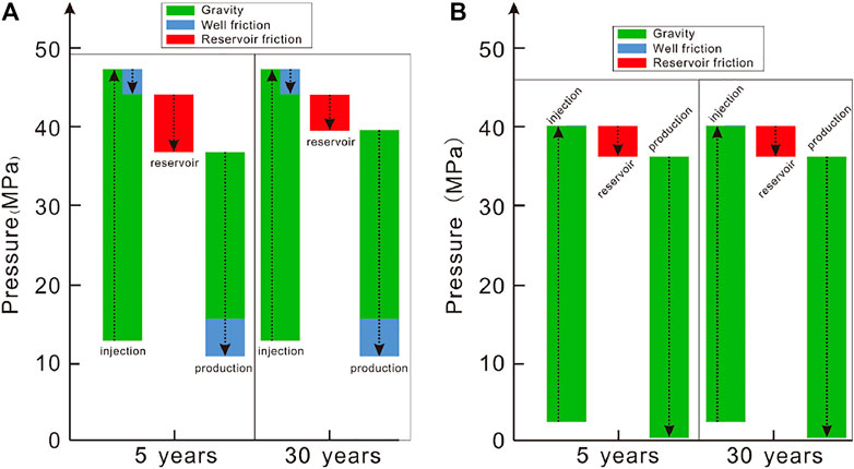
FIGURE 7. Pressure changes along the flow path for (A) the CO2-based and (B) H2O-based EGS based on simulations. Arrow upward denotes an increase, otherwise it denotes a decrease.
The enthalpy change along the flow path is mainly contributed by the gravitational potential energy, lateral heat exchange with the surroundings in the wellbores, and heat exchange with the reservoir. The enthalpy change contributed by the gravitational potential energy is dominant in the wells for the CO2-based EGS (Figure 8A). In the early stage, a heat of ∼184 kJ per kilogram CO2 is extracted by CO2 from the reservoir, which decreases to 108 kJ in the late stage due to the decrease in the reservoir temperature. For the H2O-based EGS, the contributions to the enthalpy change by the gravitational potential and lateral heat exchange are similar in the wells (Figure 8B). A heat of 490 kJ per kilogram H2O is extracted by H2O (Figure 8B). Hence, H2O exhibits a high heat-carrying capacity due to its high heat capacity. To obtain the same heat extraction rate as H2O, the CO2 mass rate should be 2.6 times of that of H2O.
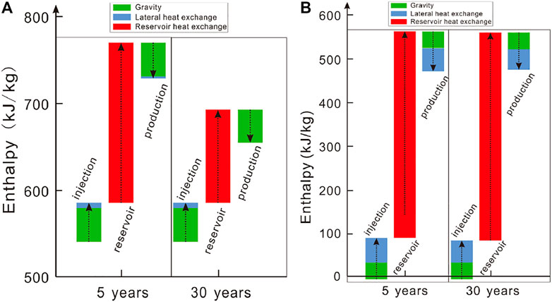
FIGURE 8. Enthalpy changes along the flow path for (A) the CO2-based and (B) H2O-based EGS based on simulations. In both cases, the reference state (zero enthalpy) is chosen as (T, P) = (20°C, 10 MPa). Arrow upward denotes an increase, otherwise it denotes a decrease.
Figure 9 shows the state change of pressure–temperature–enthalpy diagram along the flow path. The CO2-based EGS is significantly affected by the Joule–Thomson effect of CO2, which reduce the temperature in the production well (Figure 9B). The disadvantage can be weakened in the CO2-based EGS under high-pressure conditions.
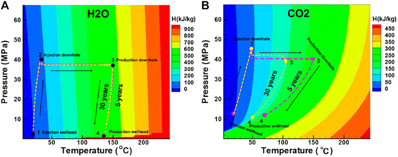
FIGURE 9. State (P, T, E) change along the flow path for (A) the H2O-based and (B) CO2-based EGS.
3.2 Sensitivity Analysis to Operation Conditions
Operation conditions (i.e., injection pressure and temperature as well as production pressure) exhibit a key effect on the EGS performance. To examine the effect, sensitivity analysis to these key parameters (Table 2) is performed. The parameters that are not listed in Table 3 are the same as the base case.

TABLE 3. Parameters used in sensitivity analysis based on the base case.
3.2.1 Effect of the Injection and Production Pressures
Compared to the base case, the results of Case 1 and Case 2 (Figures 10A–C) reveal that the increase in the operation pressure for the CO2-based EGS leads to a slight decrease in the net heat extraction rate and mass-flow rate, albeit clearly increase of the production temperature. This is related to the fact that the increase in the operation pressure would shift the curve upward in Figure 9B, indicative of the decreased Joule–Thomson effect. The comparison of the base case, Case 3, and Case 4 ((Figures 10A–C) reveals that the increase in the operation pressure difference leads to the increase in the net heat extraction rate and mass-flow rate and weakly decreases the wellhead temperature. The results of Case 5 and Case 6 demonstrate that the CO2-based EGS can run under a negative pressure difference (Pinj − Ppro < 0), indicating that CO2 can circulate without the need for external pumping. The phenomenon is attributed to the high compressibility and expansivity of CO2. The simulated results for the H2O-based EGS (Figures 10D–F) reveal that the net heat extraction rate and mass-flow rate are only related to the operation pressure difference.
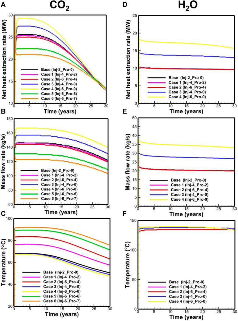
FIGURE 10. Performance of (A) net heat extraction rate, (B) mass-flow rate, (C) temperature for the CO2-based EGS, (D) net heat extraction rate, (E) mass-flow rate, and (F) temperature for the H2O-based EGS.
3.2.2 Effect of Injection Temperature
Effects of the injection temperature on the performance of CO2-based and H2O-based EGS are different. For the CO2-based EGS, the high injection temperature leads to the low downhole pressure in the injection well, thereby decreases the pressure gradient in the reservoir and ultimately reduces the mass-flow rate and net heat extraction (Figure 11A). The slight temperature difference is observed in the late stage of heat extraction, which is related to the different temperature decrease rates in the reservoir. For the H2O-based EGS, the effect of injection temperature on the flow viscosity is superior to the effect of pressure gradient. Therefore, a high injection temperature leads to a high mass-flow rate (Figure 11B). However, the net heat extraction rate is inverse because the additional heat from the production is less than that from the injection.
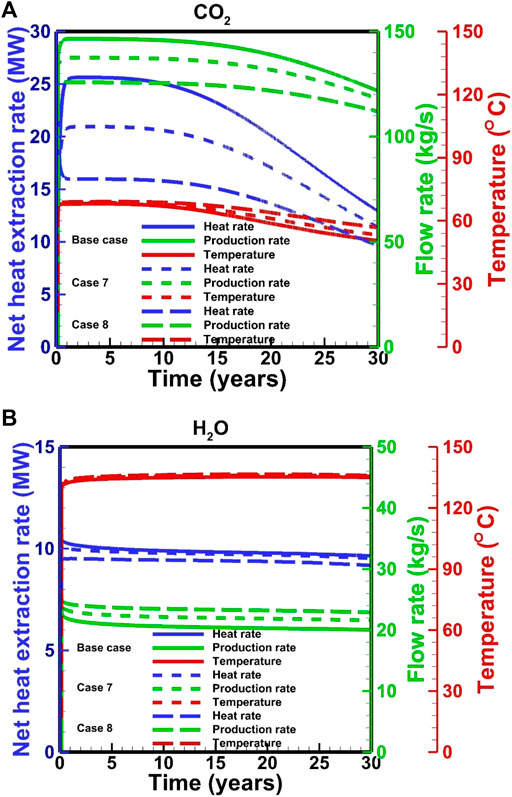
FIGURE 11. Effect of injection temperature on the performance for (A) the CO2-based and (B) H2O-based EGS.
3.3 System Optimization for Heat Extraction
EGS stable operation requires a minimal temperature drop and the maximal net heat extraction during the development period. For the comparison of CO2 with H2O, a target temperature drop is set as 20°C at the bottom of the production well after 30 years. For a specific EGS site, the most easily optimized parameter is the wellhead pressure. To prevent the damage of the reservoir by high pressure, the maximal pressure in the reservoir is limited to the value of 1.5 times of the initial pressure (56.25 MPa). Considering the strong Joule–Thomson effect of CO2 in the wellbore, the wellhead pressure in the production well should be as high as possible to obtain the maximal temperature in the CO2-based EGS. Based on a simple calculation method for the pressure and temperature distribution proposed by Atrens et al. (2010), the estimated maximal allowed wellhead pressures in the production and injection wells for the CO2-based EGS are ∼25 and 20 MPa, respectively. The pressure differences from 1 to 15 MPa with an interval of 1 MPa are used in the simulation for the system optimization of the H2O-based EGS. For CO2, the negative pressure differences (e.g.,
The optimal pressure difference is ∼10 MPa for a temperature drop limitation of 20°C for the H2O-based EGS (Figure 12). The corresponding net heat extraction rate, flow rate, and production temperature are 22.9 MW, 47.4 kg/s, and 124°C, respectively. For CO2, the numerical result reveals that the negative pressure difference should not be greater than 5.0 MPa. Otherwise, the driving force is not always sufficient to drive CO2 to the wellhead. The net heat extraction and flow rate at the low operation pressure are greater than that at the high operation pressure, but the wellhead temperature exhibits an inverse relationship (Figure 13). Under the temperature drop limitation, when the injection pressure increases from 11.7 to 19.7 MPa, the production wellhead temperature increases from 76 to 86°C (Figure 14). The corresponding flow rate and net heat extraction slightly increase. The negative pressure differences change from −4.1 MPa to −2.1 MPa, indicating that a large driving force is required at the high operation pressure. The optimal pressures for the CO2-based EGS are the maximal limited pressure of 19.7 MPa (implying that the operation pressure is as high as possible) at the injection well and 21.8 MPa at the production well. The corresponding net heat extraction rate, flow rate, and production temperature are 16.3 MW, 105.4 kg/s, and 86°C, respectively. Clearly, the heat extraction performance using CO2 is worse than that using H2O under the temperature drop limitation. However, the negative pressure difference for CO2 may lead to lower power consumption to maintain fluid circulation. Moreover, the low reactivity between CO2 and formation can prevent scaling and formation plugging, and large amounts of CO2 could be stored by heat extraction. These features make CO2 competitive with H2O for heat extraction.
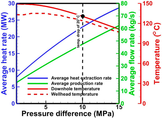
FIGURE 12. Effect of pressure difference on performance for the H2O-based EGS.
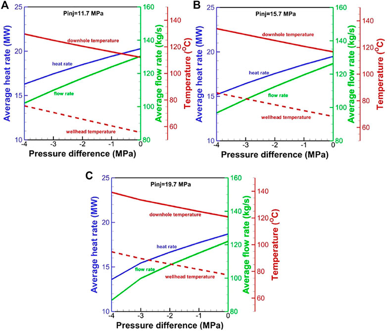
FIGURE 13. Effect of pressure difference on performance for the CO2-based EGS at the wellhead pressure of (A) 11.7 MPa, (B) 15.7 MPa, and (C) 19.7 MPa in the injection well.
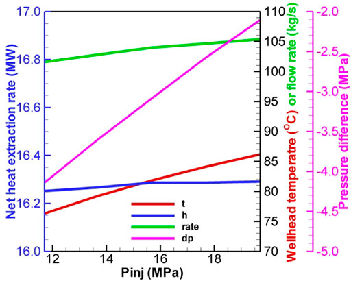
FIGURE 14. Effect of injection pressure on performance with the temperature drop limitation for the CO2-based EGS.
4 Concluding Remarks
CO2 is recently considered as a competitive working fluid in comparison to H2O for extracting heat from hot dry rocks. A coupled wellbore/reservoir simulation is conducted to comprehensively compare the performance of both fluids. The following major conclusions are drawn:
(1) At a fixed wellhead pressure difference, the net heat extraction and flow rate are greater for CO2 than those for H2O due to a large pressure gradient in the reservoir and high density gradient within CO2-base system, but the wellhead temperature is far lower in CO2-base system than that in H2O-base system due to the strong Joule–Thomson effect of CO2 in the wellbore.
(2) In the wellbore, the pressure change is mainly affected by gravity. For CO2, the frictional pressure drop accounts for 9–18% due to the high flow velocity. The enthalpy change is mainly contributed by the gravitational potential for CO2, while it is mainly contributed by the gravitational potential and lateral heat exchange for H2O.
(3) The heat extraction performance for H2O depends on the pressure difference at the wellheads and injection temperature, while the performance of CO2-based system depends on the pressure and temperature at the wellhead of injection well and production well. A high running pressure is favorable for improving the heat extraction performance (especially the production temperature) for CO2. A high injection temperature cannot increase the net heat extraction.
(4) With the constraint of temperature drop of 20°C at the bottom of the production well, the heat extraction performance by using H2O as the working fluid is better than that by using CO2. The optimal pressure difference is ∼10 MPa for H2O. The corresponding net heat extraction rate, flow rate, and production temperature are 22.9 MW, 47.4 kg/s, and 124°C, respectively. The optimal pressures for the CO2-based EGS are the maximal limited pressure of 19.7 MPa (implying that the operation pressure is as large as possible) at the injection wellhead and 21.8 MPa at the production wellhead. The corresponding net heat extraction rate, flow rate, and production temperature are 16.3 MW, 105.4 kg/s, and 86°C, respectively.
The present results are limited to the given conditions and parameters. However, the numerical experiments provide a critical insight into the hydrodynamic and heat-transfer processes for the H2O-based and CO2-based EGS considering the coupled wellbore/reservoir systems. The critical evaluation of modeling results can provide a reference to design the H2O-based and CO2-based EGS. In future studies, the realistic fracture network after fracturing should be considered in the model.
Data Availability Statement
The original contributions presented in the study are included in the article/supplementary material, further inquiries can be directed to the corresponding author.
Author Contributions
HL contributed to all of the study.
Funding
This study was supported by the National Natural Science Foundation of China (Grant Nos. 41602255 and 51809259).
Conflict of Interest
The author declares that the research was conducted in the absence of any commercial or financial relationships that could be construed as a potential conflict of interest.
Publisher’s Note
All claims expressed in this article are solely those of the authors and do not necessarily represent those of their affiliated organizations, or those of the publisher, the editors and the reviewers. Any product that may be evaluated in this article, or claim that may be made by its manufacturer, is not guaranteed or endorsed by the publisher.
References
Atrens, A. D., Gurgenci, H., and Rudolph, V. (2010). Electricity Generation Using a Carbon-Dioxide Thermosiphon. Geothermics 39, 161–169. doi:10.1016/j.geothermics.2010.03.001
Aunzo, Z. P., Bjornsson, G., and Bodvarsson, G. S. (2011). Wellbore Models GWELL, GWNACL, and HOLA User’s Guide. USA: Caliornia.
Bongole, K., Sun, Z., Yao, J., Mehmood, A., Yueying, W., Mboje, J., et al. (2019). Multifracture Response to Supercritical CO 2 ‐EGS and water‐EGS Based on Thermo‐hydro‐mechanical Coupling Method. Int. J. Energ. Res 43 (13), 7173–7196. doi:10.1002/er.4743
Brown, D. (2000). “A Hot Dry Rock Geothermal Energy Concept Utilizing Supercritical CO2 Instead of Water,” in Proceedings of the Twenty-Fifth Workshop on Geothermal Reservoir Engineering, Stanford University, January 24-26, 2000, 233–238.
Cui, G., Ren, S., Dou, B., and Ning, F. (2021). Geothermal Energy Exploitation from Depleted High-Temperature Gas Reservoirs by Recycling CO2: The Superiority and Existing Problems. Geosci. Front. 12 (6), 101078. doi:10.1016/j.gsf.2020.08.014
Goodman, A., Bromhal, G., Strazisar, B., Rodosta, T., Guthrie, W. F., Allen, D., et al. (2013). Comparison of Methods for Geologic Storage of Carbon Dioxide in saline Formations. Int. J. Greenhouse Gas Control. 18, 329–342. doi:10.1016/j.ijggc.2013.07.016
Hu, L., Pan, L., and Zhang, K. (2012). Modeling Brine Leakage to Shallow Aquifer through an Open Wellbore Using T2WELL/ECO2N. Int. J. Greenhouse Gas Control. 9, 393–401. doi:10.1016/j.ijggc.2012.05.010
Huang, X., Zhu, J., Niu, C., Li, J., Hu, X., and Jin, X. (2014). Heat Extraction and Power Production Forecast of a Prospective Enhanced Geothermal System Site in Songliao Basin, China. Energy 75, 360–370. doi:10.1016/j.energy.2014.07.085
Jiang, G. Z., Li, W. W., Rao, S., Shi, Y. Z., Tang, X. Y., Zhu, C. Q., et al. (2016). Heat Flow, Depth-Temperature, and Assessment of the Enhanced Geothermal System (EGS) Resource Base of continental China. Environ. Earth Sci. 75 (22). doi:10.1007/s12665-016-6238-5
Li, M., Gou, Y., Hou, Z., and Were, P. (2015). Investigation of a New HDR System with Horizontal wells and Multiple Fractures Using the Coupled Wellbore-Reservoir Simulator TOUGH2MP-WELL/EOS3. Environ. Earth Sci. 73 (10), 6047–6058. doi:10.1007/s12665-015-4242-9
Luo, F., Xu, R.-N., and Jiang, P.-X. (2014). Numerical Investigation of Fluid Flow and Heat Transfer in a Doublet Enhanced Geothermal System with CO 2 as the Working Fluid (CO 2 -EGS). Energy 64, 307–322. doi:10.1016/j.energy.2013.10.048
Metz, B., Davidson, O., Coninck, H. D., Loos, M., and Meyer, L. (2005). Carbon Dioxide Capture and Storage-Special Report of the Intergovernmental Panel on Climate Change. Cambridge: Cambridge University Press.
MIT (2006). The Future of Geothermal Energy—Impact of Enhanced Geothermal Systems (EGS) on the United States in the 21st Century. An Assessment by an MIT-Led Interdisciplinary Panel. Boston, MA, USA: Massachusetts Institute of Technology, 372.
Murphy, H., Brown, D., Jung, R., Matsunaga, I., and Parker, R. (1999). Hydraulics and Well Testing of Engineered Geothermal Reservoirs. Geothermics 28 (4-5), 491–506. doi:10.1016/s0375-6505(99)00025-5
Orr, F. M. (2004). Storage of Carbon Dioxide in Geologic Formations. J. Pet. Techn. 56 (9), 90–97. doi:10.2118/88842-jpt
Pan, F., McPherson, B. J., and Kaszuba, J. (2017a). Evaluation of CO2-Fluid-Rock Interaction in Enhanced Geothermal Systems: Field-Scale Geochemical Simulations. Geofluids 2017, 1–11. doi:10.1155/2017/5675370
Pan, L., Freifeld, B., Doughty, C., Zakem, S., Sheu, M., Cutright, B., et al. (2015). Fully Coupled Wellbore-Reservoir Modeling of Geothermal Heat Extraction Using CO 2 as the Working Fluid. Geothermics 53, 100–113. doi:10.1016/j.geothermics.2014.05.005
Pan, L. H., Oldenburg, C. M., Wu, Y. S., and Pruess, K. (2011). T2Well/ECO2N Vession 1.0: Multiphase and Non-isothermal Model for Coupled Wellbore-Reservoir Flow of Carbon Dioxide and Variable Salinity Water. Earth Science Division. Berkeley: Lawrence Berkeley National Laboratory, University of California.
Pan, L., and Oldenburg, C. M. (2014). T2Well-An Integrated Wellbore-Reservoir Simulator. Comput. Geosciences 65, 46–55. doi:10.1016/j.cageo.2013.06.005
Pan, L., Spycher, N., Doughty, C., and Pruess, K. (2017b). ECO2N V2.0: A TOUGH2 Fluid Property Module for Modeling CO2-H2O-NACL Systems to Elevated Temperatures of up to 300°C. Greenhouse Gas Sci. Technol. 7 (2), 313–327. doi:10.1002/ghg.1617
Pruess, K. (2006). Enhanced Geothermal Systems (EGS) Using CO2 as Working Fluid-A Novel Approach for Generating Renewable Energy with Simultaneous Sequestration of Carbon. Geothermics 35 (4), 351–367. doi:10.1016/j.geothermics.2006.08.002
Pruess, K., and Narasimhan, T. N. (1985). A Practical Method for Modeling Fluid and Heat Flow in Fractured Porous media. Soc. Pet. Eng. J. 25 (6), 14–26. doi:10.2118/10509-pa
Pruess, K., and Narasimhan, T. N. (1982). On Fluid Reserves and the Production of Superheated Steam from Fractured, Vapor-Dominated Geothermal Reservoirs. J. Geophys. Res. 87 (B11), 9329–9339. doi:10.1029/jb087ib11p09329
Pruess, K., Oldenburg, C., and Moridis, G. (1999). TOUGH2 User’s Guide, Version 2.0. Berkeley: Earth Science Division, Lawrence Berkeley National Laboratory, University of California.
Pruess, K. (2008). On Production Behavior of Enhanced Geothermal Systems with CO2 as Working Fluid. Energ. Convers. Manag. 49 (6), 1446–1454. doi:10.1016/j.enconman.2007.12.029
Ram Mohan, A., Turaga, U., Shembekar, V., Elsworth, D., and Pisupati, S. V. (2013). Utilization of Carbon Dioxide from Coal-Based Power Plants as a Heat Transfer Fluid for Electricity Generation in Enhanced Geothermal Systems (EGS). Energy 57, 505–512. doi:10.1016/j.energy.2013.05.047
Rasmusson, K., Tsang, C.-F., Tsang, Y., Rasmusson, M., Pan, L., Fagerlund, F., et al. (2015). Distribution of Injected CO2in a Stratified saline Reservoir Accounting for Coupled Wellbore-Reservoir Flow. Greenhouse Gas Sci. Technol. 5 (4), 419–436. doi:10.1002/ghg.1477
IPCC (2014). “Climate Change 2014: Synthesis Report,” in Contribution of Working Groups I, II and III to the Fifth Assessment Report of the Intergovernmental Panel on Climate Change. Editors R K Pachauri, and L A Meyer (Geneva, Switzerland: IPCC), 151.
Shi, Y., Song, X., Shen, Z., Wang, G., Li, X., Zheng, R., et al. (2018). Numerical Investigation on Heat Extraction Performance of a CO2 Enhanced Geothermal System with Multilateral wells. Energy 163, 38–51. doi:10.1016/j.energy.2018.08.060
Singh, M., Tangirala, S. K., and Chaudhuri, A. (2020). Potential of $$\hbox {CO}_{2}$$ Based Geothermal Energy Extraction from Hot Sedimentary and Dry Rock Reservoirs, and Enabling Carbon Geo-Sequestration. Geomech. Geophys. Geo-energ. Geo-resour. 6 (1), 32. doi:10.1007/s40948-019-00139-8
Wang, C.-L., Cheng, W.-L., Nian, Y.-L., Yang, L., Han, B.-B., and Liu, M.-H. (2018). Simulation of Heat Extraction from CO2-based Enhanced Geothermal Systems Considering CO2 Sequestration. Energy 142, 157–167. doi:10.1016/j.energy.2017.09.139
White, C. M., Strazisar, B. R., Granite, E. J., Hoffman, J. S., and Pennline, H. W. (2003). Separation and Capture of CO2from Large Stationary Sources and Sequestration in Geological Formations-Coalbeds and Deep Saline Aquifers. J. Air Waste Manag. Assoc. 53 (6), 645–715. doi:10.1080/10473289.2003.10466206
Xu, R., Zhang, L., Zhang, F., and Jiang, P. (2015a). A Review on Heat Transfer and Energy Conversion in the Enhanced Geothermal Systems with water/CO2as Working Fluid. Int. J. Energ. Res. 39 (13), 1722–1741. doi:10.1002/er.3352
Xu, T., Feng, G., Hou, Z., Tian, H., Shi, Y., and Lei, H. (2015b). Wellbore-reservoir Coupled Simulation to Study thermal and Fluid Processes in a CO2-based Geothermal System: Identifying Favorable and Unfavorable Conditions in Comparison with Water. Environ. Earth Sci. 73 (11), 6797–6813. doi:10.1007/s12665-015-4293-y
Zhang, F.-Z., Jiang, P.-X., and Xu, R.-N. (2013). System Thermodynamic Performance Comparison of CO2-EGS and Water-EGS Systems. Appl. Therm. Eng. 61 (2), 236–244. doi:10.1016/j.applthermaleng.2013.08.007
Zhang, F.-Z., Xu, R.-N., and Jiang, P.-X. (2016). Thermodynamic Analysis of Enhanced Geothermal Systems Using Impure CO 2 as the Geofluid. Appl. Therm. Eng. 99, 1277–1285. doi:10.1016/j.applthermaleng.2016.01.126
Nomenclature
Keywords: enhanced geothermal systems, coupled wellbore/reservoir systems, performance comparison, numerical simulation, carbon dioxide, water
Citation: Lei H (2022) Performance Comparison of H2O and CO2 as the Working Fluid in Coupled Wellbore/Reservoir Systems for Geothermal Heat Extraction. Front. Earth Sci. 10:819778. doi: 10.3389/feart.2022.819778
Received: 22 November 2021; Accepted: 19 January 2022;
Published: 18 February 2022.
Edited by:
Yanlong Kong, Institute of Geology and Geophysics (CAS), ChinaReviewed by:
Micol Todesco, Istituto Nazionale di Geofisica e Vulcanologia (INGV), ItalyGuodong Cui, China University of Geosciences Wuhan, China
Copyright © 2022 Lei. This is an open-access article distributed under the terms of the Creative Commons Attribution License (CC BY). The use, distribution or reproduction in other forums is permitted, provided the original author(s) and the copyright owner(s) are credited and that the original publication in this journal is cited, in accordance with accepted academic practice. No use, distribution or reproduction is permitted which does not comply with these terms.
*Correspondence: Hongwu Lei, aG9uZ3d1bGVpMjAwOEBhbGl5dW4uY29t