 Zhinan Hu
 Ji Zhang
 Yonggang Wang2*
94% of researchers rate our articles as excellent or good
Learn more about the work of our research integrity team to safeguard the quality of each article we publish.
Find out more
ORIGINAL RESEARCH article
Front. Earth Sci., 06 January 2023
Sec. Environmental Informatics and Remote Sensing
Volume 10 - 2022 | https://doi.org/10.3389/feart.2022.1113430
This article is part of the Research TopicAdvances in Development and Utilization of Underground SpaceView all 17 articles
Shallow bias tunnels are sensitive at the entrance section, where the existence of soil–rock interface (SRI) results in more complex deformation of surrounding rock and supporting structure. This study investigates the mechanical properties of surrounding rock and supporting structure of a shallow-buried bias tunnel crossing the soil–rock interface by a combination of model tests and numerical simulations. A shallow-buried biased tunnel with significant cracking at its entrance section is selected in southwest China. The plastic zone distribution, deformation, and pressure of surrounding rock, as well as the stress and deformation of supporting structure, are analyzed under different conditions with the tunnel vault, arch haunch, arch spring, and wall foot crossing the soil–rock interface. The test and numerical results show that the internal force of the lining structure is the largest at the left arch haunch and the right arch spring, with cracks occurring in the project. The surrounding rock and supporting structure are most prominently influenced by the arch haunch and arch spring crossing the soil–rock interface among different positions of the tunnel. The supporting structure is subjected to stress in three modes: there is mainly shearing when the tunnel vault passes through the soil–rock interface, extrusion and shearing co-exist when the tunnel arch haunch and arch spring pass through the soil–rock interface, and extrusion is dominant when the tunnel wall foot passes through the soil–rock interface. Inserting grouting steel pipes perpendicular to the soil–rock interface on the deep-buried side of the tunnel can effectively control the deformation of surrounding rock and the stress of supporting structure.
Shallow buried bias is a common phenomenon in mountain tunnels in southwest China owing to terrain conditions (Yan, 2018). For example, the shallow-buried biased section accounts for 60% of the left tube of the Nansai Tunnel of Yunnan Mangliang Expressway. Shallow-buried biased tunnels are associated with highly weathered overlying strata and weak rock mass. The weathering degree of overlying strata continues to decrease with an increase in buried depth, and a soil–rock interface (SRI) emerges between the strong weathering layer and the medium weathering layer (Kaya et al., 2017; Zhang et al., 2021). Tunnels inevitably encounter the SRI during the tunneling process and with increasing buried depth (Zhou et al., 2014; Liu X. J. et al., 2015). Then, the rock mass around the tunnel undergo extrusion and slide along the SRI due to bias pressure, and cracking or falling of secondary lining may occur, which endangers the safety of construction and operation (Yang and Wu, 2011; Chiu et al., 2017; Li et al., 2018; Qin et al., 2022).
Numerical studies on shallow-buried biased tunnels have been conducted worldwide. The deformation and mechanical behaviors of surrounding rock were revealed by characterizations of rock mass deformation (Song et al., 2018), ground surface settlement (Wang et al., 2019), surrounding rock pressure (Liu X. R. et al., 2015; Liu et al., 2017; Zhang et al., 2022), surrounding rock stress field with different bias coefficients (Qiu et al., 2022), and sensitive factors in the surrounding rock loosening zone (Qiao et al., 2021). In addition, model tests were carried out to examine surrounding rock pressure and internal force distribution of supporting structure under different terrain conditions (Lei et al., 2015; Gao and Guo, 2016), and to evaluate the effects of water immersion (Liu and Lai, 2020; Zhang et al., 2020). Kong et al. (2016, 2022), Hu et al. (2021), Liu et al. (2021), Liu et al. (2022), and Qin et al. (2022) combined site monitoring with numerical analysis to investigate the cracking characteristics of secondary lining of shallow bias tunnels. The fast Lagrandian analysis of continua in 3 dimensions (FLAC 3D) numerical model (Yang et al., 2013; Xiao et al., 2014; Xiao et al., 2016; Yang et al., 2020) and model tests (He et al., 2015; Lei et al., 2016) were employed to explore the cracking behaviors and mechanisms of shallow bias tunnels. Furthermore, shaking table model tests were conducted to explore the dynamic responses, damage mechanisms, and failure modes of shallow-buried bias tunnels subjected to dynamic loads (Xu et al., 2016; Wang et al., 2017; Jiang et al., 2018; Wang et al., 2018; Liu et al., 2019; Li et al., 2021; Sun et al., 2021).
This study is carried out based on a shallow-buried bias tunnel with severe cracking in the secondary lining of entrance section in southwest China. Model tests and numerical simulations are conducted to investigate the pressure distribution, deformation characteristics, and plastic zone of surrounding rock, and to characterize the stress of supporting structure when different positions of the tunnel cross the SRI. The failure mechanisms of supporting structure under four conditions of crossing the SRI at different positions of the tunnel are revealed. The reinforcement effect of inserting grouting steel pipes perpendicular to the SRI is also analyzed.
A left-right separated primary road tunnel in the southwest region of China is selected in this study (Figure 1). The tunnel with the design width of 10.25 m and the height of 8.55 m has a design speed of 80 km/h. The left and right tunnel tubes are 3060 and 3030 m long, respectively; their maximum burial depths are 455 and 457 m, respectively. The ground elevation of the mountain where the tunnel centerline is located ranges from 2130 to 2620 m, with a relative height of 490 m. The longitudinal slope of the right tube is 1.94%. The inlet section of the tunnel is located in the slope area in front of the mountain with a natural slope of 35°, which was basically stable before excavation.
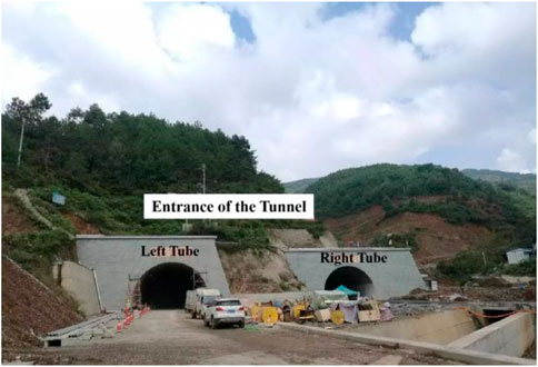
FIGURE 1. Terrain of the tunnel entrance section.
The strata at the entrance of the tunnel from top to bottom consist of gravel-containing silty clay, gravel, and strongly weathered basalt, along with a small amount of moderately weathered basalt (Figure 2). Both gravel-containing silty clay and gravel have a limited anti-scouring ability, while joints and fissures are well developed in highly weathered basalt, resulting in broken soft rock with poor self-stabilizing capacity.

FIGURE 2. Geological cross-section profile of the tunnel entrance section.
Cracks of the secondary lining appeared at the entrance section of the right tunnel tube after pouring. The maximum width and depth of the cracks were 2.18 and 245 mm, respectively. The lining cracks developed from k35+780 to k35+815. The cracks mainly extended longitudinally along the tunnel axis and paralleled each other. The cracks were primarily located at the left arch haunch and the right wall foot (Figure 3; Hu et al., 2021). The detailed cracking states and site investigation methods can be referred to the literatrue of Hu et al. (2021).
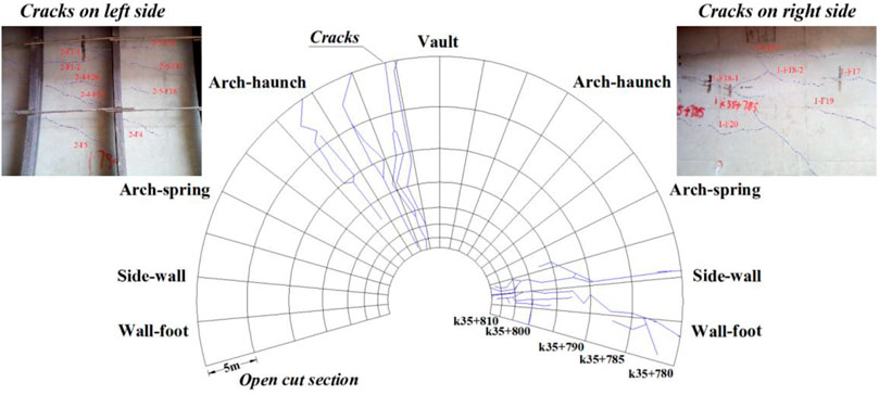
FIGURE 3. Crack distribution of secondary lining at the entrance section of the tunnel.
The entrance section of the tunnel consists of an open section (5 m) and a buried section. The buried section adopts a composite lining, and the design of composite lining supporting structure is shown in Figure 4 (Hu et al., 2021).
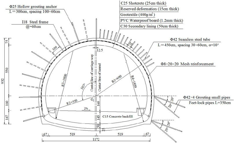
FIGURE 4. Supporting system of the tunnel mined section (units: cm).
The model scale is 1 : 50, and the model test is designed according to the similarity theory. A similar material of surrounding rock is prepared with barite powder, silt, and oil (Figure 5A); lining support material is prepared with gypsum, water, and barite powder (Figure 5B; Xu et al., 2021). The shear strength of the model material of surrounding rock and the mechanical performance of gypsum are shown in Figure 6.
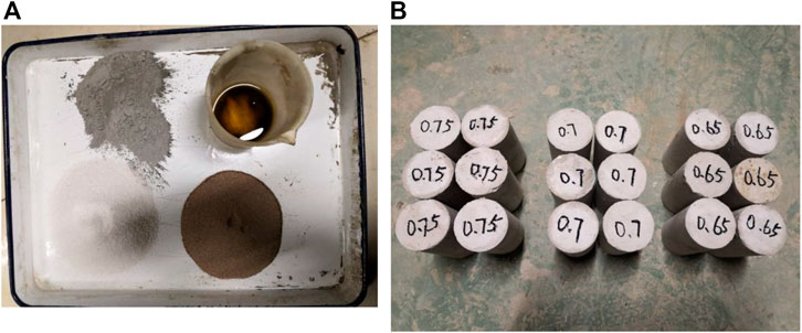
FIGURE 5. Materials used for orthogonal tests: (A) Surrounding rock material preparation and (B) Gypsum specimens.
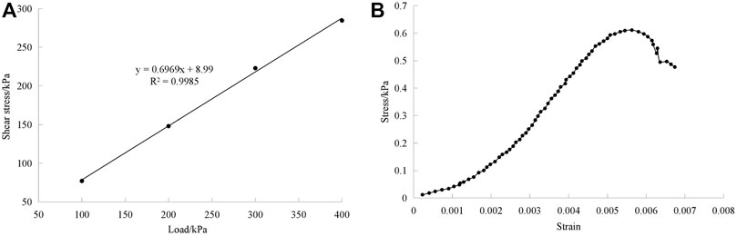
FIGURE 6. Material properties: (A) Shear strength of similar material of surrounding rock and (B) Mechanical performance of gypsum.
The ratio of mechanical parameters closest to similar materials is selected, namely, .5: .08: .42 for the upper ground layer, .65: .25: .1 for the lower rock layer, and 1 : .9: .2 for the initial support material. The mechanical parameters of the materials for model tests of surrounding rock and supporting structure are summarized in Table 1.
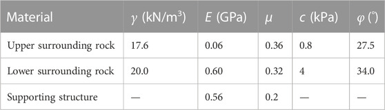
TABLE 1. Mechanical parameters of model materials for the surrounding rock and supporting structure.
The following parameters are measured in the model tests: the circumferential internal force (resistance strain gauge) on both sides of the supporting structure, the principal stress of the supporting structure (0°–45°–90° resistance strain rosette), the surrounding rock pressure (foil miniature earth pressure cell), and the surface displacement (linear displacement meter). The cross-section layout of the test elements is shown in Figure 7A. The model tests are carried out in a visual tunnel model test chamber (1.50 m × .75 m × 1.0 m) with two reserved openings based on the upper and lower bench excavation method. Excavation of the upper half section is 4 cm ahead of the lower half section, and the cyclical footage is 4 cm (Figure 7B).
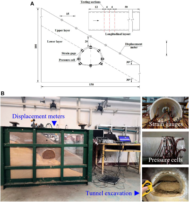
FIGURE 7. Model tests: (A) Cross-section layout of test elements and (B) Photographs of model tests.
Strain rosettes are laid on the 12-cm section of the lining structure, and variation in the first principal stress of the lining structure monitoring part with the excavation step is calculated. The first principal stress at each monitoring point increases with the advance of tunnel excavation (Figure 8). There is a slow increase in the first principal stress on the outside of the structure, which reaches its maximum value at 16.5 kPa in the vault (Figure 8A). Specifically, the first principal stress in the left wall foot and inverted arch increases remarkably after the first excavation step of the upper bench. It continues to increase slowly after passing the monitoring section and then levels off.
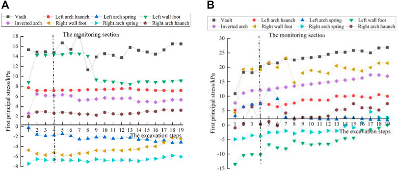
FIGURE 8. First principal stress of lining structure: (A) Stress at the 12-cm section outside of the structure and (B) Stress at the 12-cm section inside of the structure.
The first principal stress on the inside of the structure increases considerably with excavation and also peaks at the vault, reaching 26.6 kPa (Figure 8B). The variation in the first principal stress is smaller on the outside than on the inside. Overall, the principal stress changes rapidly when the excavation step is just initiated. After the excavation reaches the middle of the tunnel, the principal stress basically doesn’t increase, and the mechanical conditions of the lining structure gradually stabilize to reach the final mechanical state. This indicates that excavation of the latter half section of the tunnel has minimal effect on the entrance section.
Variation in the third principal stress of the lining structure with the excavation step is illustrated in Figure 9. In the course of tunnel excavation, the third principal stress at each monitoring point outside the structure exhibits an overall slow upward trend with minor changes (Figure 9A). The maximum compression exists near the right wall foot, with the third principal stress of −23.6 kPa. When the excavation approaches the monitoring section, the third principal stress value at the left arch-spring and the left wall foot increases suddenly.
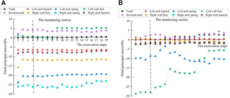
FIGURE 9. Third principal stress of lining structure: (A) Stress at the 12-cm section outside of the structure and (B) Stress at the 12-cm section inside of the structure.
Distinct changes occur in the third principal stress on the inside of the lining structure (Figure 9B). Before the excavation, the third principal stress is located at the left wall foot, with the third principal stress of −28.3 kPa. After the excavation is completed, the largest third principal stress occurs at the left arch spring, −13.6 kPa. The third principal stress at the vault is first compressed and then tensioned during excavation, whereas at other points of the lining structure, the stress decreases minimally. With continuous advance of excavation distance, the third principal stress at each part of the lining gradually decreases and tends to be stable.
Data are collected from the inner and outer strain gauges at the two monitoring sections on the model. The final circumferential strain values are used to obtain the circumferential stress of the monitoring points on the monitoring section of the lining model. On the outer side of the supporting structure, the vault is compressed most seriously at −34.5 kPa and the left wall foot is tensioned the most at 29.8 kPa. On the inner side, the left wall foot is most severely compressed at −24.1 kPa and the right wall foot is tensioned to a maximum of 43.9 kPa (Figure 10). The results show that the disturbance of surrounding rock has a strong influence on the circumferential stress of supporting structure during excavation.
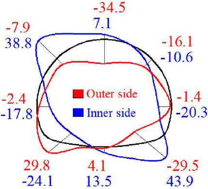
FIGURE 10. Circumferential stress of supporting structure (unit: kPa).
After the excavation is completed and the structure is stabilized, surrounding rock pressure is redistributed and dramatically changed. The trend of surrounding rock pressure (Figure 11) is consistent with that observed for the circumferential stress of the supporting structure (Figure 10). Large pressure changes also occurs at the left arch haunch (2.86 kPa) and the right wall foot (6.53 kPa), both of which are located at the SRI. This indicates that the maximum surrounding rock pressure occurs on the deep-buried side, with the peak value at the SRI.
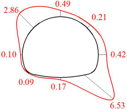
FIGURE 11. Pressure of surrounding rock (unit: kPa).
The full-scale numerical model is constructed using the FLAC 3D finite difference software, and the test results are inverted to the engineering entity for comparative analysis. The stratum and the supporting structure are simulated by solid elements using the Mohr-Coulomb model and elastic model, respectively. The SRI is simulated using interface elements (Figure 12).
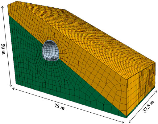
FIGURE 12. Numerical model of surrounding rock and supporting structure.
The initial supporting structure is applied after excavation. The parameters of supporting materials are calculated according to the equivalent stiffness, and the elastic modulus of steel arch and reinforcement mesh is converted to the elastic modulus of shotcrete (Yu et al., 2016; Luo et al., 2018). The conversion of elastic modulus is as follows:
The specific parameters of surrounding rock and supporting structure are listed in Table 2.
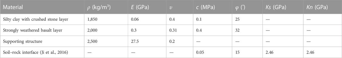
TABLE 2. Material parameters for the numerical model.
To facilitate comparison with numerical results, model test results are inversely derived into the actual scale of the project.
The vertical displacements of surrounding rock surface are compared between model tests and numerical calculations for monitoring points at the same position (Figure 13). Based on model tests, the vertical displacement curve of ground surface is similar to that of Peck curve. The maximum value appears on the right side of the tunnel centerline, but the left and right sides are asymmetrical. Within 0–15 m from the left and right sides of the tunnel centerline, there are remarkable changes in the vertical displacement of the surface on the deep-buried side. This indicates that surface displacement on the deep-buried side is strongly disturbed by excavation. The surface displacements based on numerical simulations and model tests show basically consistent patterns, although the model test results are greater than the numerical simulation results.
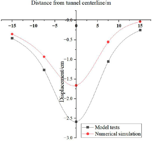
FIGURE 13. Vertical displacement of surrounding rock surface.
The first principal stress envelope curves of the supporting structure show that the maximum value is distributed in the vault and left arch haunch of the lining structure (Figure 14). As for the third principal stress of the lining structure, large values are distributed in the left arch spring and the right arch spring (Figure 15). In these parts, evident stress concentration occurs because of the following reasons: 1) due to the effect of load on the deep-buried side, the tunnel has a tendency to slip to the lower right side; and 2) due to the constraint of surrounding rock on the shallow-buried side, the arch haunch is under considerable pressure. The stress in the arch spring and inverted arch is smaller than that in other parts. The full-scale numerical simulation results are basically consistent with the final internal force distribution of the lining structure in model tests.
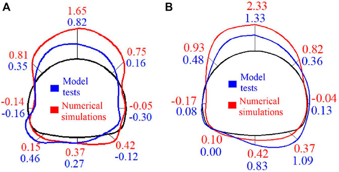
FIGURE 14. First principal stress of lining structure in numerical simulations and model tests (unit: MPa): (A) Stress outside the lining structure and (B) Stress inside the lining structure.
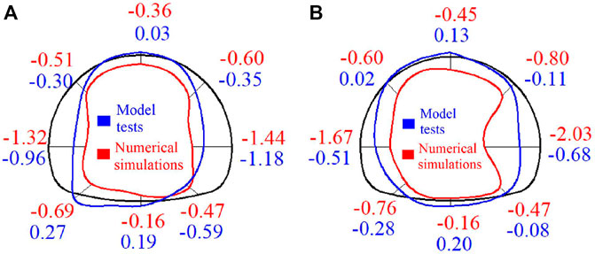
FIGURE 15. Third principal stress of lining structure in numerical simulations and model tests (unit: MPa): (A) Stress outside the lining structure and (B) Stress inside the lining structure.
The internal force distribution of the supporting structure is basically consistent between full-scale numerical simulations and model tests (Figure 16). Larger values of positive bending moment are distributed in the vault and inverted arch of the lining structure, whereas larger values of negative bending moment are distributed in the arch haunch and arch spring. There is small bending moment in other parts of the structure, and the bending moment is asymmetrically distributed due to bias (Figure 16A). The axial force values of the lining are all negative, and the lining structure is basically in a compressed state. The maximum axial force appears in the left arch spring and the right arch spring of the lining. The axial force values in the vault and the right arch haunch are relatively large, with small values in the other parts of the lining (Figure 16B). The numerical results and the test results are well-fitted.
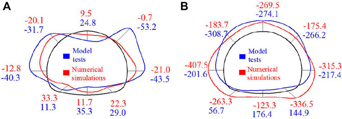
FIGURE 16. Structural internal forces in numerical simulations and model tests: (A) Bending moment of lining structure (unit: kNm) and (B) Axial force of lining structure (unit: kN).
To further reveal the relationship between the tunnel and the SRI, four relative position relationships are established, with the tunnel vault, arch haunch, arch spring, and wall foot crossing the SRI. The influence of relative position change on surrounding rock deformation and lining structure stress is analyzed. The model size is 75 m × 50 m × 37.5 m. The stratum and supporting structure are consistent with the earlier description in Section 4. The secondary lining is added to the supporting structure and simulated by solid elements using the Drucker-Prager material model. The material parameters of the secondary lining are provided in Table 3.

TABLE 3. Material parameters of secondary lining.
The deformation of surrounding rock at different positions of the supporting structure crossing the SRI is shown in Figure 17. The largest displacement of surrounding rock occurs with the arch spring crossing the SRI (2.12 cm), followed by that with the arch haunch crossing the SRI (1.36 cm). The displacement of surrounding rock with the vault and wall foot crossing the SRI is .96 and .87 cm, respectively. The maximum displacement always occurs near the vault, with a bias toward the deep-buried side. Further analysis reveals that as the SRI moves down relative to the supporting structure, surrounding rock displacement is influenced by the supporting structure more prominently.
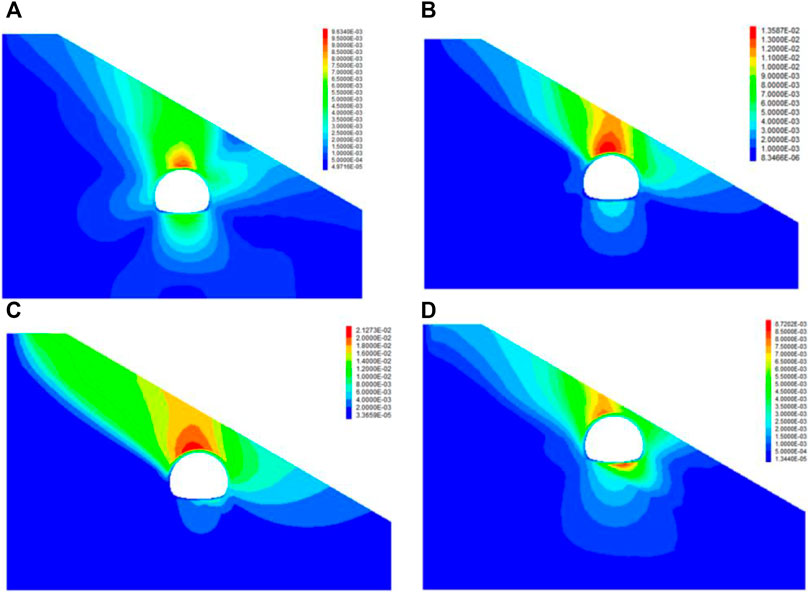
FIGURE 17. Surrounding rock displacement under four different conditions: (A) Tunnel vault crossing the soil–rock interface; (B) Arch haunch crossing the soil–rock interface; (C) Arch spring crossing the soil–rock interface; and (D) Wall foot crossing the soil–rock interface.
The plastic zone of surrounding rock at different positions of the supporting structure crossing the SRI is shown in Figure 18. The plastic zone of surrounding rock displays a distinct asymmetric distribution after tunnel excavation. It is mainly distributed in the ground layer above the SRI and shows a remarkable shear slip surface. The distribution pattern of the plastic zone is similar to that of surrounding rock deformation. When crossing the SRI, the tunnel arch haunch and arch spring impose a strong influence on the plastic zone of surrounding rock. Shear failure mainly occurs along the SRI, with tensile failure primarily on the surface and inverted arch.
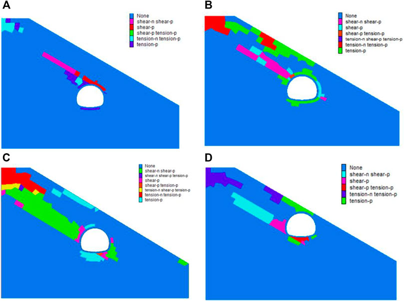
FIGURE 18. Plastic zone of surrounding rock under four different conditions: (A) Tunnel vault crossing the soil–rock interface; (B) Arch haunch crossing the soil–rock interface; (C) Arch spring crossing the soil–rock interface; and (D) Wall foot crossing the soil–rock interface.
The secondary lining stress at different positions of the supporting structure crossing the SRI is shown in Figure 19. The first principal stress is located near the vault and the left arch haunch. The first principal stress of the secondary lining reaches its maximum value at 2.3 MPa when the arch spring passes through the SRI, followed by that with the arch haunch crossing the SRI. The first principal stress at the wall foot is the lowest, only 1.02 MPa. These results indicate that above the arch spring, the first principal stress gradually decreases with the upward movement of the SRI. The largest tensile stress of the structure appears near the vault of the deep-buried side, where cracking occurs first. The structure is compressed near the arch spring and the wall foot, but within a safe range.
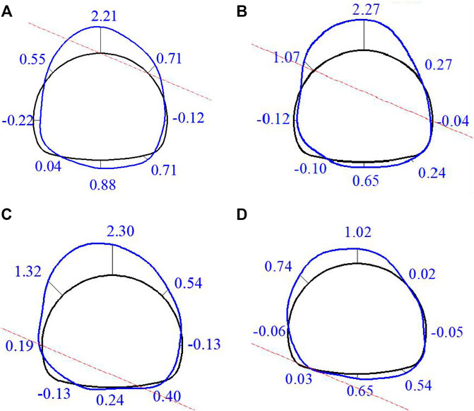
FIGURE 19. First principal stress of secondary lining under four different conditions (unit: MPa): (A) Tunnel vault crossing the soil–rock interface; (B) Arch haunch crossing the soil–rock interface; (C) Arch spring crossing the soil–rock interface; and (D) Wall foot crossing the soil–rock interface.
The deformation results of the secondary lining are uniformly enlarged by 100 times (Figure 20). When the tunnel arch spring passes through the SRI, the secondary lining deformation reaches its maximum value at 2.13 cm. In other cases, the secondary lining deformation ranks in descending order with the tunnel arch haunch, vault, and wall foot crossing the SRI. When the tunnel passes through the SRI, the upper rock and soil mass loses support because of excavation, and consequently slides along the SRI. The supporting structure is then subjected to extrusion and shearing in the following three modes.
1) With the tunnel vault crossing the SRI, the supporting structure is mainly subjected to shearing, and shear failure may occur at the vault position. 2) With the tunnel arch haunch and arch spring crossing the SRI, the supporting structure is subjected to both extrusion and shearing. Shear failure may occur at the intersection of the SRI and the tunnel, whereas tensile cracking caused by extrusion may occur on the deep-buried side of the supporting structure, and the extrusion is stronger when the tunnel arch spring passes through the SRI. 3) With the tunnel wall foot crossing the SRI, the supporting structure shows the least deformation, and the stress of the supporting structure is dominated by squeezeing. On the deep-buried side of the supporting structure, the positions of the arch haunch, the vault, and the inverted arch can produce large extrusion deformation and tensile stress. On the shallow-buried side of the supporting structure, the arch haunch to the wall foot can produce outward extrusion deformation.
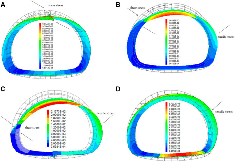
FIGURE 20. Structural displacement of secondary lining under four different conditions (unit: m): (A) Tunnel vault crossing the soil–rock interface; (B) Arch haunch crossing the soil–rock interface; (C) Arch spring crossing the soil–rock interface; and (D) Wall foot crossing the soil–rock interface.
According to the deformation characteristics of surrounding rock and supporting structure with different SRI-crossing positions, the cracking of the secondary lining is mainly attributed to the shear and extrusion of the rock mass caused by the sliding of the upper rock and soil mass after tunnel excavation. In such tunnels, the sliding of the upper rock and soil should be controlled. It is recommended to insert grouting steel pipes or anti-slide piles perpendicular to the SRI on the upper part of the deep-buried side of the tunnel. Taking the tunnel arch haunch crossing the SRI as an example, the effect of grouting steel pipes on controlling rock mass deformation and supporting structure stress is analyzed by the numerical simulation, and the specific design of grouting steel pipes is shown in Figure 21. Grouting steel pipes are simulated by anchor cable elements with the elastic modulus of 210 GPa and slurry bonding force of 15 kN.
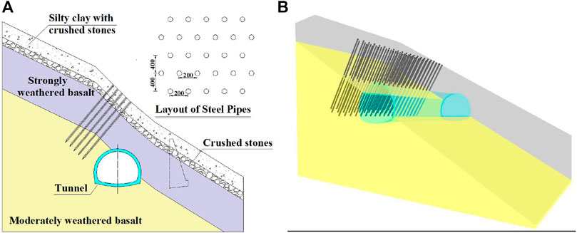
FIGURE 21. Ground reinforcement of grouting steel pipes: (A) Detailed design of grouting steel pipe and (B) Numerical simulation of ground reinforcement.
The numerical results (Figure 22) show that after inserting grouting steel pipes, the deformation of surrounding rock is reduced by 32% compared with that before inserting grouting steel pipes. In particular, the deformation is markedly reduced near the grouting steel pipes. The plastic zone of surrounding rock is also changed distinctively, the shear slip surface disappears, and the surrounding rock is only subjected to tension. In addition, the first principal stress of the secondary lining is reduced by 34% and the secondary lining is mainly squeezed after inserting grouting steel pipes. The reinforcement area of the grouting bolts is mainly subjected to unsymmetrical pressure, and the unsymmetrical pressure state of the structure disappears. Furthermore, the deformation of the secondary lining is reduced by 43.9% after inserting grouting steel pipes. In summary, both the stress and deformation of the secondary lining are effectively controlled by inserting grouting steel pipes.
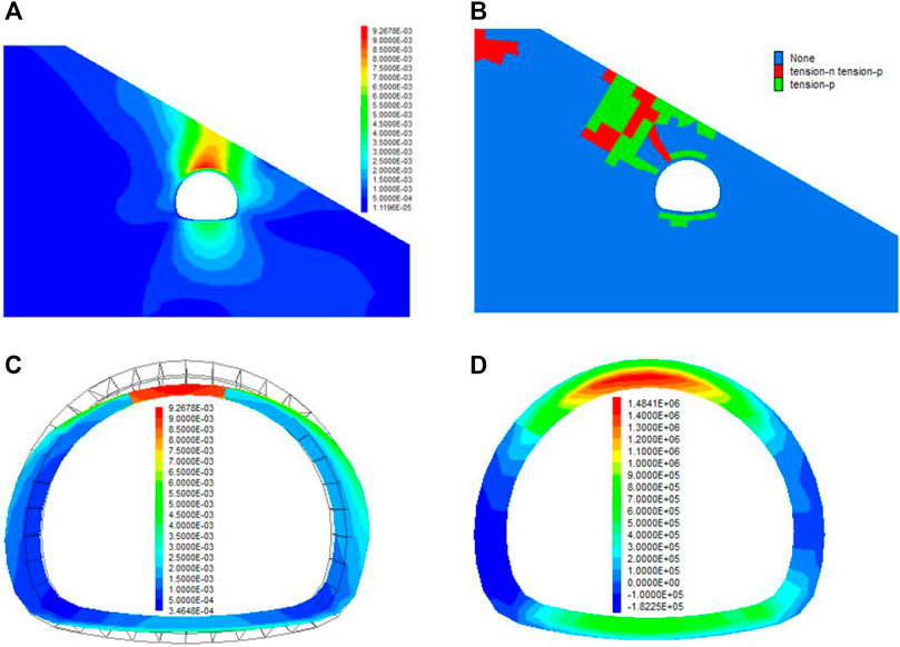
FIGURE 22. Controlling effects of grouting steel pipes: (A) Deformation of surrounding rock (unit: m); (B) Plastic zone of surrounding rock; (C) Deformation of secondary lining (unit: m); and (D) First principal stress of secondary lining (unit: Pa).
In this paper, a combination of model tests and numerical simulations is used to characterize the deformation of surrounding rock and the stress of supporting structure in a shallow-buried biased tunnel crossing the soil–rock interface (SRI). A highway tunnel in southwest China with severe cracking of the secondary lining at the entrance section is taken as an example. The major findings are as follows:
1) The surface displacement is the largest along the tunnel centerline and decreases toward both sides, with the deep-buried side being influenced more than the shallow-buried side. When the arch spring of the tunnel passes through the SRI, it has the greatest influence on the displacement of surrounding rock. The deformation of surrounding rock is smaller for the tunnel arch haunch crossing SRI than that for the tunnel arch spring crossing the SRI. When the tunnel vault and inverted arch cross the SRI, the deformation of surrounding rock is relatively small.
2) The plastic zone of surrounding rock exhibits a remarkable asymmetric distribution after tunnel excavation. It is mainly located in the stratum above the SRI on the deep-buried side of the tunnel, showing a distinct shear slip surface. The plastic zone is changed most prominently when the tunnel arch haunch or arch spring passes through the SRI, and it is least influenced when the tunnel vault passes through the SRI. The surrounding rock slides along the SRI, resulting in the first failure of the left arch haunch and the left arch spring. The plastic zone tends to continuously expand upward from the left arch haunch and has emerged in the surface soil over a large range.
3) The surrounding rock pressure peaks at the crossing positions of SRI and tunnel, when the tunnel arch haunch or arch spring passes through the SRI. The law of surrounding rock pressure is consistent with the outer circumferential stress of the supporting structure.
4) When the tunnel arch spring passes through the SRI, the first principal stress is concentrated at the left arch haunch (2.3 MPa). As the SRI moves upward relative to the tunnel position, the first principal stress at the left arch haunch decreases with the tunnel arch haunch and vault crossing the SRI, in contrast to the slow increase at the inverted arch. When the tunnel wall foot passes through the SRI, the stress is relatively low at the left arch haunch.
5) When the tunnel crosses the SRI, the supporting structure is subjected to extrusion and shearing in three different modes: mainly shearing (tunnel vault crossing the SRI), simultaneous extrusion and shearing (arch haunch and arch spring crossing the SRI), and mainly extrusion (wall foot crossing the SRI).
6) Inserting grouting steel pipes perpendicular to the SRI on the deep-buried side of the tunnel can effectively control the deformation of surrounding rock. Compared with that before inserting grouting steel pipes, the deformation of surrounding rock is reduced by 32%, and its shear slip surface disappears. In addition, the unsymmetrical pressure effect of the secondary lining is markedly alleviated, and its first principal stress is reduced by 34%.
The original contributions presented in the study are included in the article/supplementary material, further inquiries can be directed to the corresponding author.
ZH and JZ wrote the manuscript. YoW revised the manuscript, conceived the experiments, and contributed to the data interpretation. The fieldwork and preliminary study of samples were carried out by YuW. All authors have read and agreed to the published version of the manuscript.
The authors acknowledge the financial support provided by the Young Talent Program of the Hebei Provincial Education Department (BJ2019009), the National Natural Science Foundation of China (52178392), the Central Leading Local Science and Technology Development Fund Program (226Z5403G), and the Excellent Youth Program of the Hebei Provincial Natural Science Foundation (E2021210025), China.
YoW was employed by Shijiazhuang Traffic Investment Development Co., Ltd. YuW was employed by CCCC Road Bridge Inspection and Maintenance Co., Ltd.
The remaining authors declare that the research was conducted in the absence of any commercial or financial relationships that could be construed as a potential conflict of interest.
All claims expressed in this article are solely those of the authors and do not necessarily represent those of their affiliated organizations, or those of the publisher, the editors and the reviewers. Any product that may be evaluated in this article, or claim that may be made by its manufacturer, is not guaranteed or endorsed by the publisher.
Chiu, Y. C., Lee, C. H., and Wang, T. T. (2017). Lining crack evolution of an operational tunnel influenced by slope instability. Tunn. Undergr. Sp. Technol. 65, 167–178. doi:10.1016/j.tust.2017.03.004
Gao, F. Q., and Guo, J. J. (2016). Stress mechanism and deformation monitoring of bias tunnel. Int. J. Simul. Syst. Sci. Technol. 17 (43), 14.1–14.4. doi:10.5013/IJSSST.a.17.43.14
He, M., Peng, Y., Zhao, S., Shi, H. Y., Wang, N., and Gong, W. L. (2015). Fracture mechanism of inversed trapezoidal shaped tunnel excavated in 45° inclined rock strata. Int. J. Min. Sci. Technol. 25, 531–535. doi:10.1016/j.ijmst.2015.05.003
Hu, Z. N., Shen, J., Wang, Y. F., Guo, T. Z., Liu, Z. C., and Gao, X. Q. (2021). Cracking characteristics and mechanism of entrance section in asymmetrically-load tunnel with bedded rock mass: A case study of a highway tunnel in southwestsouthwest China. Eng. Fail. Anal. 122, 105221. doi:10.1016/j.engfailanal.2021.105221
Ji, T. Y., Zhang, D., Li, C. S., Shi, B., and Chen, X. X. (2016). Sensitivity analysis on gravel-soil interface parameters of the soil-rock mixture. J. Eng. Geol. 24, 1203–1208. (in China). doi:10.13544/j.cnki.jeg.2016.s1.175
Jiang, X. L., Wang, F. F., Yang, H., Sun, G. C., and Niu, J. Y. (2018). Dynamic response of shallow-buried small spacing tunnel with asymmetrical pressure: Shaking table testing and numerical simulation. Geotech. Geol. Eng. 36 (4), 2037–2055. doi:10.1007/s10706-017-0444-0
Kaya, A., Karaman, K., and Bulut, F. (2017). Geotechnical investigations and remediation design for failure of tunnel portal section: A case study in northern Turkey. J. Mt. Sci. 14, 1140–1160. doi:10.1007/s11629-016-4267-x
Kong, C., Gao, X. Q., Cao, L., and Liu, K. (2016). Analysis of the failure of primary support of a deep-buried railway tunnel in silty clay. Eng. Fail. Anal. 66, 259–273. doi:10.1016/j.engfailanal.2016.04.008
Kong, C., Wang, H. Y., Zhao, K., and Gao, X. Q. (2022). Numerical simulation of long-term deterioration of rock mass supported by shotcrete lining. Front. Earth. Sci. 10, 891084. doi:10.3389/FEART.2022.891084
Lei, M. F., Lin, D. Y., Yang, W. C., Shi, C. H., Peng, L. M., and Huang, J. (2016). Model test to investigate failure mechanism and loading characteristics of shallow-bias tunnels with small clear distance. J. Cent. S. Univ. 23, 3312–3321. doi:10.1007/s11771-016-3397-1
Lei, M. F., Peng, L. M., and Shi, C. H. (2015). Model test to investigate the failure mechanisms and lining stress characteristics of shallow buried tunnels under unsymmetrical loading. Tunn. Undergr. Sp. Technol. 46, 64–75. doi:10.1016/j.tust.2014.11.003
Li, A., Xu, N. W., Dai, F., Gu, G. K., Hu, Z. H., and Liu, Y. (2018). Stability analysis and failure mechanism of the steeply inclined bedded rock masses surrounding a large underground opening. Tunn. Undergr. Sp. Technol. 77, 45–58. doi:10.1016/j.tust.2018.03.023
Li, L., Guo, X. D., Zou, Z. Y., Zhu, Z. Y., Guo, Z. H., Xiao, W. M., et al. (2021). Study on dynamic response characteristics and damage mechanism of tunnel lining at entrance of shallow bias tunnel. Shock. Vibr. 2021, 8930560. doi:10.1155/2021/8930560
Liu, C., Yang, H., Jiang, X. L., and Shi, H. T. (2019). Shaking table test and numerical simulation for acceleration response laws of shallow-buried biased double-arch tunnel. J. Vibro. Eng. 21 (4), 1188–1200. doi:10.21595/jve.2019.20623
Liu, D. J., Li, M., Zuo, J. P., Gao, Y., Zhong, F., Zhang, Y., et al. (2021). Experimental and numerical investigation on cracking mechanism of tunnel lining under bias pressure. Thin-Walled. Struct. 163, 107693. doi:10.1016/j.tws.2021.107693
Liu, D. J., Shang, Q., Li, M., Zuo, J. P., Gao, Y., and Xu, F. (2022). Cracking behaviour of tunnel lining under bias pressure strengthened using FRP Grid-PCM method. Tunn. Undergr. Sp. Technol. 123, 104436. doi:10.1016/j.tust.2022.104436
Liu, X. J., Yang, C., and Yu, J. (2015). The influence of moisture content on the time-dependent characteristics of rock material and its application to the construction of a tunnel portal. Adv. Mater. Sci. Eng. 3, 1–13. doi:10.1155/2015/725162
Liu, X. R., Chen, H. J., Liu, K., and He, C. M. (2017). Model test and stress distribution law of unsymmetrical loading tunnel in bedding rock mass. Arab. J. Geosci. 10, 184–195. doi:10.1007/s12517-017-2949-5
Liu, X. R., Li, D. L., Wang, J. B., and Wang, Z. (2015). Surrounding rock pressure of shallow-buried bilateral bias tunnels under earthquake. Geomech. Eng. 9 (4), 427–445. doi:10.12989/gae.2015.9.4.427
Liu, Y. Y., and Lai, H. P. (2020). Experimental study on lining cracking of shallow buried loess tunnel under the simulation of effect of slide surface immersion. Appl. Sci. 10 (17), 6080. doi:10.3390/app10176080
Luo, Y. B., Chen, J. X., Chen, Y., Diao, P. S., and Qiao, X. (2018). Longitudinal deformation profile of a tunnel in weak rock mass by using the back analysis method. Tunn. Undergr. Sp. Technol. 71, 478–493. doi:10.1016/j.tust.2017.10.003
Qiao, S. F., Cai, Z. Y., Xu, P., Tan, J. K., and Zhang, Y. G. (2021). Investigation on the scope and influence factors of surrounding rock loose circle of shallow tunnel under bias pressure: A case study. Arab. J. Geo Sci. 14 (15), 1428. doi:10.1007/s12517-021-07869-8
Qin, Y. W., Lai, J. X., Yang, T., Zan, W. B., Feng, Z. H., Liu, T., et al. (2022). Failure analysis and countermeasures of a tunnel constructed in loose granular stratum by shallow tunnelling method. Eng. Fail. Anal. 141, 106667. doi:10.1016/j.engfailanal.2022.106667
Qiu, H. S., Qiu, R. H., Luo, G., Ayasrah, M., and Wang, Z. (2022). Study on the mechanical behavior of fluid–solid coupling in shallow buried tunnels under different biased terrain. Symmetry 14 (7), 1339. doi:10.3390/sym14071339
Song, D. Q., Chen, J. D., and Cai, J. H. (2018). Deformation monitoring of rock slope with weak bedding structural plane subject to tunnel excavation. Arab. J. Geosci. 11, 251–261. doi:10.1007/s12517-018-3602-7
Sun, W. Y., Yan, S. H., Ma, Q. G., Liang, Q. G., Ou, E., Cao, X. P., et al. (2021). Dynamic response characteristics and failure mode of a bias loess tunnel using a shaking table model test. Transp. Geotech. 31, 100659. doi:10.1016/j.trgeo.2021.100659
Wang, F. F., Jiang, X. L., and Niu, J. Y. (2017). The large-scale shaking table model test of the shallow-bias tunnel with a small clear distance. Geotech. Geol. Eng. 35, 1093–1110. doi:10.1007/s10706-017-0166-3
Wang, F. F., Jiang, X. L., Niu, J. Y., and Yang, H. (2018). Experimental study on seismic dynamic characteristics of shallow-bias tunnel with a small space. Shock. Vibr. 2018, 6412841–6412849. doi:10.1155/2018/6412841
Wang, Z., Yao, W. J., Cai, Y. Q., Xu, B., Fu, Y., and Wei, G. (2019). Analysis of ground surface settlement induced by the construction of a large-diameter shallow-buried twin-tunnel in soft ground. Tunn. Undergr. Sp. Technol. 83, 520–532. doi:10.1016/j.tust.2018.09.021
Xiao, J. Z., Dai, F. C., Wei, Y. Q., Min, H., Xu, C., Tu, X. B., et al. (2014). Cracking mechanism of secondary lining for a shallow and asymmetrically-loaded tunnel in loose deposits. Tunn. Undergr. Sp. Technol. 43, 232–240. doi:10.1016/j.tust.2014.05.013
Xiao, J. Z., Dai, F. C., Wei, Y. Q., Xing, Y. C., Cai, H., and Xu, C. (2016). Analysis of mechanical behavior in a pipe roof during excavation of a shallow bias tunnel in loose deposits. Environ. Earth. Sci. 75, 293–311. doi:10.1007/s12665-015-5176-y
Xu, H., Li, T. B., Xia, L., Zhao, J., and Wang, D. (2016). Shaking table tests on seismic measures of a model mountain tunnel. Tunn. Undergr. Sp. Technol. 60, 197–209. doi:10.1016/j.tust.2016.09.004
Xu, Z. L., Luo, Y. B., Chen, J. X., Su, Z. M., Zhu, T. T., and Yuan, J. P. (2021). Mechanical properties and reasonable proportioning of similar materials in physical model test of tunnel lining cracking. Constr. Build. Mater 300, 123960. doi:10.1016/j.conbuildmat.2021.123960
Yan, S. C. (2018). Defermation control of weak surounding rock unsymmetrial loading tunnel entrance section of Yibin-Bijie expressway. dissertation/master's thesis (Beijing: Beijing Jiaotong University).
Yang, C., Hu, Z. X., Huang, D., and Guo, F. (2020). Failure mechanism of primary support for a shallow and asymmetrically loaded tunnel portal and treatment measures. J. Perform. Constr. Facil. 34 (1), 19435509. doi:10.1061/(asce)cf.1943-5509.0001385
Yang, C., Zhang, Y. X., Huang, D., and Zhu, Q. (2013). Deformation behavior of topographic unsymmetrical loaded tunnels and their pre-reinforcements after excavation. Highw. Transp. Res. Dev. Engl. Ed. 7, 69–75. doi:10.1061/jhtrcq.0000334
Yang, X. L., and Wu, B. (2011). Optimization analysis of rockbolts supporting for double-arch shallow tunnels subjected to unsymmetrical loads. Geotech. Spec. Pub. 221, 88–95. doi:10.1061/47632(411)12
Yu, H. T., Chen, J. T., Bobet, A., and Yuan, Y. (2016). Damage observation and assessment of the Longxi tunnel during the Wenchuan earthquake. Tunn. Undergr. Sp. Technol. 54, 102–116. doi:10.1016/j.tust.2016.02.008
Zhang, J., Kuang, M. X., Zhang, Y. H., and Feng, T. G. (2021). Evaluation and analysis of the causes of a landslide and treatment measures during the excavation of a tunnel through a soil-rock interface. Eng. Fail. Anal. 130, 105784. doi:10.1016/j.engfailanal.2021.105784
Zhang, Y. T., Ding, X. L., Huang, S. L., Wu, Y. J., and He, J. (2020). Strength degradation of a natural thin-bedded rock mass subjected to water immersion and its impact on tunnel stability. Geomech. Eng. 21 (1), 63–71. doi:10.12989/gae.2020.21.1.063
Zhang, Y. W., Fan, S. Y., Yang, D. H., and Zhou, F. (2022). Investigation about variation law of frost heave force of seasonal cold region tunnels: A case study. Front. Earth Sci. 9, 806843. doi:10.3389/feart.2021.806843
Keywords: soil-rock interface, shallow-buried tunnel, unsymmetrical pressure, cracking feature, deformation analysis
Citation: Hu Z, Zhang J, Wang Y and Wang Y (2023) Mechanical behaviors of surrounding rock and supporting structure of shallow-buried unsymmetrical pressure tunnel crossing soil–rock interface. Front. Earth Sci. 10:1113430. doi: 10.3389/feart.2022.1113430
Received: 01 December 2022; Accepted: 15 December 2022;
Published: 06 January 2023.
Edited by:
Yuwei Zhang, Xi’an University of Architecture and Technology, ChinaReviewed by:
Chao Kong, Southwest University of Science and Technology, ChinaCopyright © 2023 Hu, Zhang, Wang and Wang. This is an open-access article distributed under the terms of the Creative Commons Attribution License (CC BY). The use, distribution or reproduction in other forums is permitted, provided the original author(s) and the copyright owner(s) are credited and that the original publication in this journal is cited, in accordance with accepted academic practice. No use, distribution or reproduction is permitted which does not comply with these terms.
*Correspondence: Yonggang Wang, d2FuZ3lvbmdnYW5nMjAyMjExQDE2My5jb20=
Disclaimer: All claims expressed in this article are solely those of the authors and do not necessarily represent those of their affiliated organizations, or those of the publisher, the editors and the reviewers. Any product that may be evaluated in this article or claim that may be made by its manufacturer is not guaranteed or endorsed by the publisher.
Research integrity at Frontiers
Learn more about the work of our research integrity team to safeguard the quality of each article we publish.