 Jun Huang
 Xingwang Liu2
 Zongyuan Ma
 Gao Lv
- 1School of Earth Sciences and Engineering, Xi’an Shi-you University, Xi’an, China
- 2Urban Construction and Transport Engineering Division, PowerChina Northwest Engineering Corporation Limited, Xi’an, China
- 3Guizhou Communications Polytechnic, Guiyang, China
- 4Hanjiang-to-Weihe River Valley Water Diversion Project Construction Co.LTD, Xi’an, China
Simple, fast, and reliable methods for the stability evaluation of tunnels can facilitate the construction and development of tunneling projects. The problems related to tunnel stability at this stage can be well analyzed via theoretical analysis method, model test method, or numerical analysis method. On the other hand, those methods are hard to be effectively analyzed these projects with higher importance, shorter decision and design period, and more urgent construction period. This paper proposed research works on the stability evaluation of clay tunnels. Firstly, a state function with the variables of stress and strain state is presented to predict the stress and strain states of surrounding rocks caused by tunnel excavation, which characterize the physical-mechanical state of surrounding rocks (also called stability state). Secondly, the non-linear deterioration of the physical and mechanical properties of surrounding rocks will be simulated, and the expressions and calculation methods of the tunnel stability reserve factor will be yielded. Finally, the results of the proposed method were compared with the strength reduction method and the limit equilibrium method with a clay tunnel example. The comparison between the three feature points of the arch crown, sidewall, and arch bottom showed that the stability reserve factor of the clay tunnel was smaller than those of the strength reduction method and the limit equilibrium method. The values of limit displacement obtained by the proposed method were closer to the field monitoring data than that of the strength reduction method. Therefore, this study could be better applied to the stability evaluation of clay tunnels.
1 Introduction
Research in tunnel stability evaluation is very important for the safe construction and operation of tunnel projects. Modern subway tunnels have short construction cycles and high construction and operation safety requirements. Thus, tunnel engineers need to process the project more rapidly, and more efficiently, and make stability analysis decisions accurately. Therefore, tunnel stability evaluation is facing challenges i.e., rapid response, decision-making judgment, prevention and disposal, and the need for further in-depth optimization.
At present, the research methods of tunnel stability can be summarized as the empirical, theoretical, experimental, and numerical analysis methods (Song et al., 2001; Osman et al., 2006; Son and Cording, 2008; Yang and Yang, 2009; Fraldi and Guarracino, 2010; Yang and Huang, 2013; Shiau and Al-Asadi, 2020; Song and Marshall, 2020; Tan et al., 2020; Tyagi et al., 2020; Yertutanol et al., 2020; Li L. P. et al., 2021; Pandit and Sivakumar, 2021; Liu et al., 2022a; Zhang et al., 2022a; Zhang Z. et al., 2022; Hao et al., 2022; Lu et al., 2022; Qin et al., 2022; Li et al., 2023; Xue et al., 2023). The primary purpose of these methods is to obtain more effective and accurate stability analysis results and provide a more reliable basis for the actual tunnel construction and operation decisions. Early researchers (Broms and Bennermark, 1967; Davis et al., 1979; Mair, 1979; Rowe and Kack, 1983; Assadi and Sloan, 1991a; Assadi and Sloan, 1991b; Leca and Dormieux, 1991; Sloan and Assadi, 1991; Mair et al., 1993) usually relied on the experience to evaluate the stability of tunnels due to the lack of theoretical basis. The experience of tunnel construction is accumulated with the development of geotechnical theory and technology. The researchers (Lee and Park, 2000; Lyamin et al., 2001; Wang et al., 2001; Lee et al., 2006; Fraldi and Guarracino, 2009; Wilson et al., 2011; Yang and Huang, 2011; Fan et al., 2013; Rojat et al., 2015) considering more influencing factors to evaluate the stability of tunnels and formed the corresponding stability evaluation methods and techniques. The tunnel stability evaluation methods have been developed by the emergence of more adverse factors and complex environmental conditions with the continuous development of tunnel construction. Since the researchers of tunnel stability evaluation focus on the response of surrounding rocks’ stress field and deformation field caused by tunnel excavation, tunnel model tests (Marshall et al., 2012; Shiau and Al-Asadi, 2020; Song and Marshall, 2020; Yertutanol et al., 2020; Lu et al., 2022; Sun et al., 2022; Qin et al., 2023a; Qin et al., 2023b) is used to reveal the rule of the stress field and deformation field of surrounding rocks by excavation. The model’s test of tunnel experimental (Franza, 2019; Huang et al., 2019; Zhang et al., 2020), in-situ, and centrifugal, can be well revealed the failure pattern. The stress distribution and deformation characteristics of surrounding rocks will help to understand tunnel stability research. Researchers (Liu et al., 2020; Antão et al., 2021; Fernández et al., 2021; Han et al., 2021; Nguyen and Nguyen-Son, 2022; Pelech et al., 2022; Zhuo et al., 2022; Qin et al., 2023c) established numerical models based on the numerical method, e.g., finite element method or discrete element method with the continuous improvement of computer performance and the development of computing technology. Numerical modeling is closer to the accurate geometric scale, surrounding rock materials, loading effects, boundary conditions, etc., and visualizes the process of surrounding rock loading evolution. Numerical methods can solve the construction problems faced by large tunnel projects effectively, and promote tunnel engineering development. Currently, the methods of tunnel stability are not limited to a narrow field. These methods (Sukkarak et al., 2019; Shiau and Al-Asadi, 2020; Kumar and Jain, 2021; Li T. Z. et al., 2021; Liu et al., 2022b; Zhang et al., 2022b; Man et al., 2022; Xue et al., 2022; Xue et al., 2023) are not only applied to but also inspired by other fields of research. The researchers of tunnel stability problems still have the power of sustainable development.
Researchers are still trying to find more operational, more straightforward physically meaningful, and applicable methods for tunnel stability evaluation problems. In this paper, a clay tunnel project is used as the case study, and the deterioration characteristics of the physical and mechanical properties of surrounding rocks are taken into account. The development of surrounding rocks from the stable to the limit state until the failure. This paper introduced a strategy for the deterioration of the strength and deformation resistance of surrounding rocks for tunnel stability evaluation.
2 State function of clay tunnel surrounding rocks
The general failure of tunnel loading can be summarized into two cases. The first one is the redistribution of stresses in surrounding rocks and destabilization is yield due to the stress is exceeded the limit value (the accumulated deformation before stress failure may not exceed the limit). The second type of instability is due to the cumulative deformation caused by excavation-induced restraint relaxation exceeding the limit (the stress state may not exceed the limit at this time). The basic idea of the strength reduction method is to allow the material strength to deteriorate until the material reaches its ultimate state. In general, the failure of clay tunnels has been corresponding to both cases described. The deterioration of the strength and deformation resistance in surrounding rocks should take into account to evaluate stability reserves.
According to the basic knowledge of solid mechanics, elastic mechanics, and material mechanics, it is known that stress redistribution occurs in clay strata due to tunnel excavation, which leads to the change of stress-strain state in surrounding rocks. The stress state at a point in surrounding rocks can be characterized by the stress and strain of this point at this moment. So it assumed the existence of a state function Fs, which was a function of the stress state and strain state at a point in surrounding rocks. It was that the state function could reflect the stress state characteristics of surrounding rocks. The expression of the state function FS was as follows.
Where
According to the definition of the state function, when the stress state or strain state of any point in surrounding rocks reaches the limit state, it can be considered that the state function at that point reaches the limit state at this time. There should be three limit states at a point in surrounding rocks.
1) A point of surrounding rocks stress state and strain state have reached the limit state:
2) Only the stress state at a point of surrounding rocks reaches the limit state:
3) Only the deformation at a point of surrounding rocks reaches the limit state:
1) if
2) if
3) if
These can be used as guidelines to distinguish the stability state of tunnel surrounding rocks. Then, these guidelines can play an important role when the engineer needs to evaluate the tunnel stability quantitatively. According to strength theory, the limit state of surrounding rocks at a point can be considered as the limit stress or strain state, which depends on the strength or deformation resistance of surrounding rocks. Then, since the physical and mechanical properties of surrounding rocks deteriorate during the redistribution of stress due to excavation, the objective of quantitative evaluation of the stability of surrounding rocks can be achieved by characterizing the evolution of their deterioration.
3 Method of characterizing the deterioration of surrounding rocks
The stability state evolution of the tunnel surrounding rocks can be described as follows: stable to the limit state, and reach the failure. In the whole state of the evolution process, the physical and mechanical state of surrounding rocks is constantly changed, while the quantitative evaluation of the stability reserve of the tunnel surrounding rocks only needs to measure the “distance” between the physical and mechanical state of the surrounding rocks at the stable and the limit state. “Large distance” indicates that the surrounding rocks are more stable. According to the strength theory, the limit state of a point of surrounding rocks depends on its strength or deformation resistance, while the failure state indicates that the physical and mechanical state at that point exceeds the limit state. Therefore, the deterioration of the physical and mechanical properties of the surrounding rock can be used to bring it closer to the actual state of stress at that point. The quantitative parameters which reflect the deterioration can be used to measure the stability reserve of the tunnel surrounding rocks at that point. This method considering the deterioration of the physical and mechanical properties of surrounding rocks is called the strength-deformation parameter deterioration method.
3.1 Principle of strength-deformation parameter deterioration method
The stability reserve of a tunnel can be estimated via the strength-deformation parameter deterioration method, and simulating the deterioration of the physical and mechanical properties of surrounding rocks reach the limit state. The failure mechanism of the clay tunnel failure mechanism can be divided into tensile and shear failure. Tensile failure also can be regarded as a generalized shear failure. Therefore, at a point of surrounding rocks, the stress state can be determined by its shear stress, and strength parameters can characterize the shear strength. The strain state can be determined by the deformation of that point, and the strength parameters and deformation parameters can characterize the deformation resistance at that point. A function (Eq. 2) that takes the shear stress and strain state into account can represent the state of the point.
Where
If the shear stress state or strain state of any point in surrounding rocks reaches the ultimate stress state or ultimate strain state, the state function at that point will reach the limit state. This paper established a method taking the coupled deterioration of strength and deformation resistance into account. To distinguish from the previous method, which only considers the strength deterioration of surrounding rocks, this paper assumed the limit state for the state function, as shown below.
The strength and deformation resistance deterioration process is described as a form of strength and deformation resistance reduction, such as the strength reduction method. Based on the above analysis and the core idea of the strength-deformation parameter deterioration method, the basic idea of this method was expressed as follows when exploring the stability of clay tunnels by changing the limit state of surrounding rocks at a certain point (
Where D is the deterioration coefficient, which can measure the quantitative parameter of the deterioration of physical and mechanical properties at a point in surrounding rocks, and the value is constantly greater than zero.
Then, combining Eqs. 2, 3, the strength-deformation parameter deterioration method was expressed as that,
Where
The strength-deformation parameter deterioration method is applied by first reducing the shear strength and the deformation resistance simultaneously, stopping the iterative calculation once the tunnel is in the limit state. The shear strength corresponds to a strength deterioration coefficient and deformation resistance deterioration coefficient (which
According to Eqs. 4, 5, the stability reserve factor of the tunnel surrounding rocks
The parameters affecting the shear strength of the clay are cohesion c and the internal friction angle φaccording to Coulomb’s law. The parameters of the deformation resistance of clay are as follows: the cohesion c and the internal friction angle φ, Young’s modulus E, and Poisson’s ratio ν. Eq 5 can be expressed as
Eq 8 can be expressed as
Then, according to Eqs. 6, 8, the stability reserve factor of surrounding rocks can be further calculated.
3.2 Calculation of the deterioration coefficients
Coulomb’s law can also be expressed by the shear strength of clay as
The strength deterioration coefficient of clay can be obtained by referring to the principle of the strength reduction method. For example,
Where
Where E0 is the initial Young’s modulus of clay,
From Eq. 13, the deterioration coefficient of Young’s modulus can be calculated by the following equation.
According to Eq. 14, we will obtain the following expressions.
If let
According to the Mohr-Coulomb theory, the yield strength can be expressed as the following equation.
Therefore, when c0 and φ0 are reduced by the strength deterioration coefficient Ds, the new cohesion and internal friction angle can be substituted into Eq. 18. It also indicates the effect of the deterioration coefficient of Young’s modulus
It was found that Poisson’s ratio change on stress, strain, and displacement could be far less than the impact of other parameters, so Poisson’s ratio deterioration was not considered here.
3.3 The physical meaning of the strength-deformation parameter deterioration method
The specific physical meaning of the strength-deformation parameter deterioration method was given in Figure 1. The coordinate of a point on the constitutive curve is
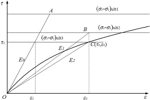
FIGURE 1. Non-linear stress-strain relationship in hardening soil.
In summary, the actual state changes of surrounding rocks deterioration during tunnel excavation and the stability evaluation of clay tunnels with non-linear behavior can be better simulated by the strength-deformation parameter deterioration method (simultaneous reducing of the cohesive force c, the internal friction angle φ, and Young’s modulus E). Both the strength and deformation parameters can be reduced by the same scale factor when simulating the deterioration process of the physical and mechanical properties of surrounding rocks, and the different contributions of these parameters to the limit state can also be reflected. At the same time, when the strength and deformation resistance of surrounding rocks is weakened, the displacement of surrounding rocks at a point will increase, making the surrounding rocks more prone to instability. The cohesion, internal friction angle, Young’s modulus, Poisson’s ratio of the deterioration coefficients and the scale factor
Generally, if the strength and deformation parameters are all known, the stress, strain, and displacement of a point of surrounding rocks can be calculated according to the relevant theory of geotechnics. The strength or deformation parameters are variables in these formulas and have different relationships with the dependent variables (stress, strain, displacement), which also reflects the different influences of these parameters. Therefore, in the numerical analysis of clay tunnels using the strength-deformation parameter deterioration method, the process of non-linear deterioration of the physical and mechanical properties of surrounding rocks can be better simulated, although the strength and deformation parameters are reduced by the same scale factor. If the clay’s physical-mechanical properties make surrounding rocks reach the limit state at a point during the process, the tunnel stability reserve factor is equal to the scale factor.
To sum up, the key point of the strength-deformation parameter deterioration method (referred to as “the proposed method”) is that the strength and deformation parameters are continuously reduced with the scale factor until the limit state. The specific calculation step is shown in Figure 2.

FIGURE 2. Calculation step of strength-deformation parameter deterioration method.
3.4 Limit state conditions of tunnel numerical model
Many researchers have proposed a variety of limit state criteria for tunnel numerical model, among which the more widely used are 1) the connectivity of the plastic zone, 2) the abrupt and accelerated increase in strain or displacement at the feature points of surrounding rocks, and 3) the non-convergence of numerical calculation. This paper used a hyperbolic model to fit the stress-strain relationship of clay, there was no plastic strain and plastic zone. Then the above criterion 1) could not apply to this proposed method, but it could still be used for the strength reduction method.
The field monitoring data indicates that surrounding rocks may have great deformation before the abrupt stress, strain, or displacement change. Furthermore, adopting the hyperbolic principal model, which is closer to the actual mechanical behavior of the clay, also makes the numerical analysis of the tunnel deformation field closer to reality. Finally, the displacement (or strain) at a point of surrounding rocks is itself a comprehensive response to the physical and mechanical properties of surrounding rocks under the external load. Therefore, this paper adopted the allowable relative convergence value between two measurement points as a further criterion for identifying the tunnel stability state, which can be described as follows: when the displacement (or strain) changes abruptly and the calculation does not converge, if the relative convergence value between two feature points in surrounding rocks does not exceed the limit value, the tunnel surrounding rocks is identified to be in the limit state.
For a clay tunnel, if the defined state function is a one-point displacement function of the surrounding rock, then its limit state corresponds to the displacement limit state. Table 1 shows the allowable values of relative convergence ω of tunnels which can be calculated by linear interpolation of the tunnel burial depth. The allowable limit displacement
Where d is the diameter of the tunnel. The parameter depth is the burial depth of the tunnel in Table 1.
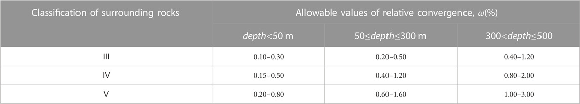
TABLE 1. Allowable values of relative convergence around tunnels and caverns (from GB50086-2015 in China).
4 Limit equilibrium method for clay tunnel stability evaluation
4.1 The wedge-shaped failure mechanism of surrounding rocks
This paper derived the analytical formula of the stability reserve factor of the tunnel surrounding rocks via the limit equilibrium analysis theory and took the more ideal clay tunnel surrounding rocks loading mechanics model into account, analogous to the slope safety factor idea. The limit equilibrium method takes the failure mechanism of the wedge-shaped block as an example according to Terzaghi’s theoretical soil mechanics.
4.2 Mechanics of wedge-shaped collapsing block in clay surrounding rocks
It assumed that the collapsing block is wedge-shaped in the circular clay tunnel, and the stability reserve factor can be calculated by the limit equilibrium method. The mechanics of the wedge-shaped collapsing block (the block is rigid) is shown in Figure 3, and clay conforms to rigid plastic constitutive relation.
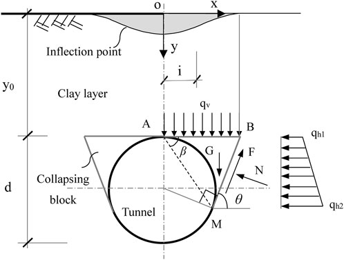
FIGURE 3. Two-dimensional mechanical model of the wedge-shaped collapsing block in a circular tunnel.
y0 is the tunnel burial depth and d is the tunnel diameter. According to symmetry, the right-hand part ABM of the wedge-shaped collapsing block is chosen as the calculation object. The angles between the wedge failure lines BM and the horizontal plane are
The stability reserve factor for the collapsing block can be defined as:
4.3 Limit equilibrium analysis based on the mechanical model of wedge-shaped failure
The static equilibrium equation of the wedge can be listed according to Figure 3. The main loads in this model are as follows: G is the self-weight of the right-hand collapsing block ABM,
Where,
Where
Where
The formula for calculating the vertical soil stress acting on the collapsing block ABM is expressed as follows.
According to the Gaussian curve of ground settlement (the shadow area in Figure 3),
Where
The combined vertical pressure can be calculated by the following equation for the collapsing block ABM.
Where
The horizontal pressure acting on the sliding surface BM of the collapsing block ABM can be calculated according to the following equation.
where the parameter
Finally, we can obtain the stability reserve factor for the clay tunnel surrounding rocks by substituting the anti-slip force and slip force on the sliding surface calculated from the wedge failure mechanics model into Eq. 22.
5 An example application of stability analysis of clay tunnels
5.1 Engineering overview and cross-sectional geometry of a clay tunnel
The Yinchuan-Xi’an high-speed railway tunnel was used as a study case in this paper. The tunnel mainly traverses across the loess plateau area, and most of the strata powder clay layer. The tunnel section at DK267+457.1 was selected for the study. The burial depth of the tunnel at this location is 170.5 m, the span D is about 12.75 m, and the height H is about 11.50 m. The radii of these arcs are R=10.50 m, R1=8.78 m, R2=7.10 m, and R3=1.50 m, and the angle α is
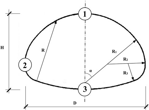
FIGURE 4. Schematic diagram of the shape, dimensions, and feature points of the clay tunnel cross-section.
To facilitate the validation of the proposed method, it was assumed that the stratum is a single isotropic and homogeneous clay layer, and the physical and mechanical parameters of the clay can be given in Table 2. It was also assumed that the constitutive model of the clay is hyperbolic and satisfies the Mohr-Coulomb yield criterion of non-associated flow. To apply the strength reduction method, it assumed the clay is an ideal elastic-plastic material, while all other conditions are consistent. The length of the left and right boundaries of the numerical model of the clay tunnel is more than 3 times the span from the center axis of the tunnel. The left and right boundaries are respectively constrained horizontally, the bottom boundary is fixed, and the upper boundary is free. This tunnel stability evaluation could be considered a plane strain problem.

TABLE 2. Physical and mechanical parameters of clay.
5.2 Analysis of the results of different methods
A numerical model for tunnel stability evaluation was developed based on a tunnel section of the Yinchuan-Xi’an high-speed railway. Firstly, the strength reduction method and the proposed method were used to analyze the stability of the same tunnel finite element model; secondly, based on the geometry and material parameters of this tunnel, it was assumed that a wedge-shaped failure mechanism also occurs in this tunnel, so that the limit equilibrium analysis method could be used to calculate the tunnel stability reserve factor; finally, the results of the three stability analyses were compared.
First of all, the key point of both the strength reduction method and the method is to simulate the deterioration of the physical and mechanical properties of surrounding rocks as realistically as possible, and the scale factor is a quantitative description of the deterioration mechanism of surrounding rocks so that the displacement of the feature point of surrounding rocks will change with the change of the scale factor. When the scale factor increases to a certain level, the actual rock condition is at the limit, and the scale factor can be regarded as the stability reserve factor of the tunnel, which is given by the abrupt change of the displacement-scale factor curve at the point of the scale factor (Figures 5–6). Although the scale factors of the intensity reduction method and the proposed method are close in the range of values, the results of these two methods are not only different in value but also the physical meaning. The proposed method not only simulates the deterioration process of the strength parameters but also couples the deterioration process of the deformation parameters of surrounding rocks, which is closer to reality. Moreover, the strength reduction method only considers strength deterioration in the analysis process, and can not represent the realistic representation of the actual change in the deformation field of surrounding rocks during the deterioration process for clay. The constitutive relationship is consistent with either the elastic or elastoplastic model.
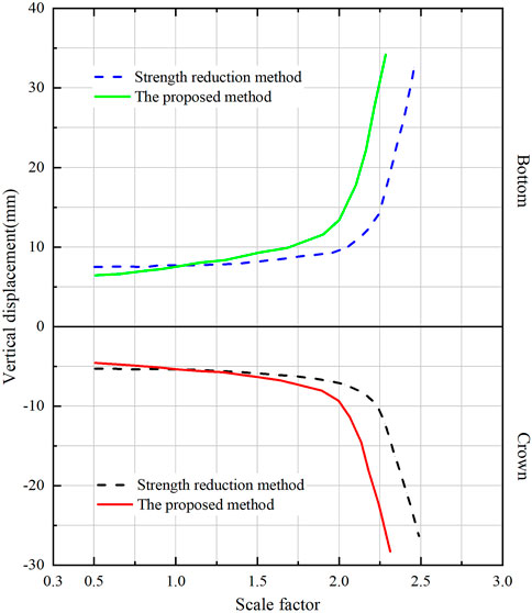
FIGURE 5. Scale factor versus vertical displacement of two feature points in the crown and bottom of the arc.
The three feature points of the tunnel correspond to three key locations, such as the arc crown, the sidewall, and the arc bottom. The displacements of each feature point are different, and the direction of displacement of the arc crown is vertical (settlement), the direction of displacements of two feature points in the left and right sidewall are horizontal, and these values are equal due to the symmetry. The direction of displacement of the arch bottom is vertical displacement (uplift). The displacement values of the feature points based on the strength reduction method are generally smaller than those based on this paper’s method when the scale factor is less than one. However, the relationship between the two magnitudes is reversed (Figures 5, 6; Table 3) when the scale factor is greater than one. Meanwhile, the allowable limit displacement of feature points (also as the recommended limit displacement) can be calculated by Eq. 30, according to the classification of surrounding rocks, the tunnel depth, tunnel diameter, and the allowable values of relative convergence specified in Table 4. The limit displacements of feature points (the displacement value corresponding to the abrupt curve change in Figures 5, 6 calculated by the proposed method are closer compared with the recommended limit displacement values. The actual deformation field in the tunnel stability evaluation will be predicted via the proposed method. It also reflects the variation of the displacement with the physical and mechanical properties of the clay with a small scale factor corresponding to the abrupt change in displacement. The analysis results indicate that the actual stability reserve of the tunnel is smaller than the evaluation results of the strength-deformation method (Table 5). This paper took the strength-deformation property deterioration of surrounding rocks into account to reflect the actual stress or deformation fields and achieve the goal of better evaluation of the tunnel stability reserve.
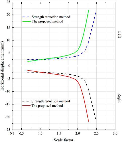
FIGURE 6. Scale factor versus horizontal displacement of two feature points in the sidewall.
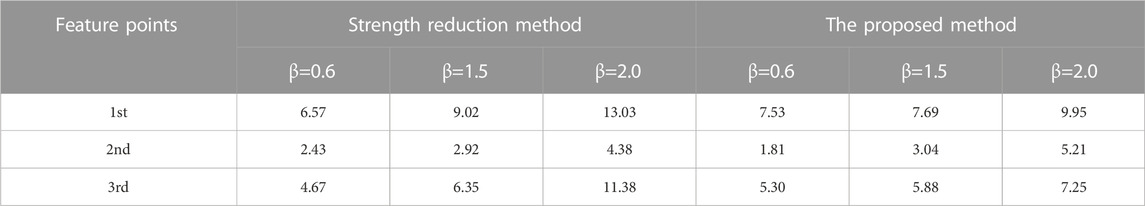
TABLE 3. Displacement of each feature point with different scale factors (Unit: mm).
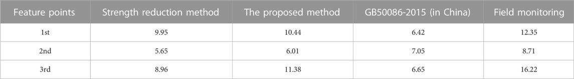
TABLE 4. Limit displacement at feature points in surrounding rocks obtained by different methods (Unit: mm)

TABLE 5. Stability reserve factors of the tunnel calculated by different methods.
The stability reserve factor calculated by the limit equilibrium method based on the wedge-shaped collapsing block (θ=π/4+φ/2) is significantly larger than the other two results significantly. The limit equilibrium method can not reflect the actual state, because the tunnel cross section is circular instead of the one shown in Figure 4. More assumptions will be used in the calculation process of the limit equilibrium method. The tunnel stability reserve factors obtained from the displacement-scale factor curves of the different feature points are relatively close, despite the different types and directions of displacement at the different feature points. This analysis shows that the overall tunnel stability can also be reflected by the stability reserve factor of a single point, and this method is recommended in preference.
6 Conclusion
The method suggested in this paper provides a practical and efficient way to evaluate the stability reserve of clay tunnels. The following conclusions can be drawn based on theoretical analysis and example calculation results.
1) The stress and deformation fields in the surrounding rock will be redistributed by tunnel excavation. The state function FS is defined with the stress state and strain state of a point as variables, which can comprehensively characterize the stability state of the point at this moment.
2) The formula for calculating the tunnel stability reserve factor Sf from the actual state FS0 at a point of the surrounding rock and its limit state FSL at a point of the surrounding rock is established with the definition of the state function. Then, taking the non-linear relationship between this limit state and the physical and mechanical properties of the surrounding rock into account, the non-linear deterioration of the physical and mechanical properties of the surrounding rock is simulated to calculate the tunnel stability reserve factor. The strength and deformation parameters that characterize the clay properties are discounted by a scaling factor until the limit state is close to or equal to the actual state.
3) An analytical formula for the calculation of the tunnel stability reserve factor by the limit equilibrium method is established based on the physical model of wedge-shaped failure of the surrounding rock.
4) The analysis results of a clay tunnel project example show that the non-linear deterioration process of physical and mechanical properties of the surrounding rock will be better predicted by the proposed method in this paper. Compared with the strength reduction and the limit equilibrium methods, could the proposed method in this paper have more reliable quantitative evaluation results of tunnel stability.
5) The analysis results in this paper could provide broader and more valuable references in the study of clay tunnel stability problems and also support the engineering practice. However, tunnel stability is also closely related to construction factors for the actual tunnel construction. Therefore, construction factors such as construction methods and support forms should be introduced into tunnel stability evaluation as variables as well and guided the construction of tunnel projects.
Data availability statement
The original contributions presented in the study are included in the article/Supplementary Material, further inquiries can be directed to the corresponding author.
Author contributions
JH was in charge of conceptualization, funding acquisition, writing of the original draft, and editing. XL was in charge of data resources and analysis. ZM was in charge of the development of the mathematical model of the research and overall supervision of the whole research investigation. GL was in charge of the numerical simulations. KD was in charge of the post-processing data.
Funding
This work was supported by the Science and technology innovation fund project of Hanjiang-to-Weihe river valley water diversion project construction Co. LTD. (Grant No. 2020302), Open Research Fund Program of State Key Laboratory of Eco-hydraulics in Northwest Arid Region (Grant No. 2018KFKT-16), Shaanxi Provincial Urban and Rural Construction Science and Technology Research and Development ProgramProject (2020-K41), National Natural Science Foundation of China (51806173).
Acknowledgments
The authors would like to thank Shaanxi Key Lab of Petroleum Accumulation Geology for providing high-performance computing devices.
Conflict of interest
XL was employed by PowerChina Northwest Engineering Corporation Limited: KD was employed by Hanjiang-to-Weihe River Valley Water Diversion Project Construction Co.LTD.
The authors declare that this study received funding from Hanjiang-to-Weihe river valley water diversion project construction Co. LTD. The funder had the following involvement in the study: the funder participated in the data processing.
The remaining authors declare that the research was conducted in the absence of any commercial or financial relationships that could be construed as a potential conflict of interest.
Publisher’s note
All claims expressed in this article are solely those of the authors and do not necessarily represent those of their affiliated organizations, or those of the publisher, the editors and the reviewers. Any product that may be evaluated in this article, or claim that may be made by its manufacturer, is not guaranteed or endorsed by the publisher.
References
Antão, A. N., Vicente da Silva, M., Monteiro, N., and Deusdado, N. (2021). Upper and lower bounds for three-dimensional undrained stability of shallow tunnels. Transp. Geotech. 27, 100491. doi:10.1016/j.trgeo.2020.100491
Assadi, A., and Sloan, S. (1991b). “Stability of a shallow circular tunnel in cohesive-frictional soil,” in International Conference on Finite Element Methods.
Assadi, A., and Sloan, S. (1991a). Undrained stability of shallow square tunnel. J. Geotechnical Eng. 117117 (8), 11528–21173. doi:10.1061/(asce)0733-9410(1991)117:8(1152)
Broms, B. B., and Bennermark, H. J. (1967). Stability of clay at vertical opening. Soil Mech. Found. Div. J. 193 (1), 71–94. doi:10.1061/JSFEAQ.0000946
Davis, E. H., Gunn, M. J., Mair, R. J., and Seneviratne, H. N. (1979). The stability of shallow tunnels and underground openings in cohesive material. Géotechnique 30, 397–416. doi:10.1680/geot.1980.30.4.397
Duncan, J. M., and Chang, C. Y. (1970). Nonlinear analysis of stress and strain in soils. J. Soil Mech. Found. Div. ASCE 96 (5), 1629–1653. doi:10.1061/JSFEAQ.0001458
Fan, W., Yu, M., Deng, L., Peng, X., and Chen, L. (2013). New strength formulae for rock surrounding a circular opening. Can. Geotechnical J. 50 (7), 735–743. doi:10.1139/cgj-2012-0001
Fernández, F., Rojas, J. E. G., Vargas, E. A., Velloso, R. Q., and Dias, D. (2021). Three-dimensional face stability analysis of shallow tunnels using numerical limit analysis and material point method. Tunn. Undergr. Space Technol. 112, 103904. doi:10.1016/j.tust.2021.103904
Fraldi, M., and Guarracino, F. (2010). Analytical solutions for collapse mechanisms in tunnels with arbitrary cross sections. Int. J. Solids Struct. 47 (2), 216–223. doi:10.1016/j.ijsolstr.2009.09.028
Fraldi, M., and Guarracino, F. (2009). Limit analysis of collapse mechanisms in cavities and tunnels according to the Hoek–Brown failure criterion. Int. J. Rock Mech. Min. Sci. 46 (4), 665–673. doi:10.1016/j.ijrmms.2008.09.014
Franza, A., Marshall, A. M., and Zhou, B. (2019). Greenfield tunnelling in sands: The effects of soil density and relative depth. Géotechnique 69 (4), 297–307. doi:10.1680/jgeot.17.P.091
Han, K., Wang, L., Su, D., Hong, C., Chen, X., and Lin, X. (2021). An analytical model for face stability of tunnels traversing the fault fracture zone with high hydraulic pressure. Comput. Geotechnics 140, 104467. doi:10.1016/j.compgeo.2021.104467
Hao, X., Yuan, L., Sun, Z., Zhao, Y., Ren, B., Zhao, D., et al. (2022). An integrated study of physical and numerical modelling on the stability of underground tunnel influenced by unloading rate. Tunn. Undergr. Space Technol. 129, 104602. doi:10.1016/j.tust.2022.104602
Huang, M., Wang, H., Yu, J., and Tang, Z. (2019). Undrained stability analysis of a plane strain circular tunnel using streamline velocity fields. Int. J. Geomechanics 19 (5), 06019006. doi:10.1061/(ASCE)GM.1943-5622.0001395
Kumar, J., and Jain, H. (2021). Elasto-plastic ground settlement response and stability of single and twin circular unsupported and supported tunnels. Transp. Geotech. 30, 100620. doi:10.1016/j.trgeo.2021.100620
Lade, P. V., and Duncan, J. M. (1975). Elasto-plastic stress-strain theory for cohesionless soil with curved yield surfaces. J. Geotechnical Eng. Div. 101 (10), 1019–1035. doi:10.1016/0020-7683(77)90073-7
Leca, E., and Dormieux, L. (1991). Upper and lower bound solutions for the face stability of shallow circular tunnels in frictional material. Géotechnique 40 (4), 581–606. doi:10.1680/geot.1990.40.4.581
Lee, C. J., Wu, B. R., Chen, H. T., and Chiang, K. H. (2006). Tunnel stability and arching effects during tunneling in soft clayey soil. Tunn. Undergr. Space Technol. 21 (2), 119–132. doi:10.1016/j.tust.2005.06.003
Lee, I. M., and Park, J. K. (2000). Stability analysis of tunnel keyblock: A case study. Tunn. Undergr. Space Technol. 15 (4), 453–462. doi:10.1016/S0886-7798(01)00014-1
Li, L. P., Shang, C. S., Chu, K. W., Zhou, Z. Q., Song, S. G., Liu, Z. H., et al. (2021). Large-scale geo-mechanical model tests for stability assessment of super-large cross-section tunnel. Tunn. Undergr. Space Technol. 109, 103756. doi:10.1016/j.tust.2020.103756
Li, T. Z., Gong, W. P., and Tang, H. M. (2021). Three-dimensional stochastic geological modeling for probabilistic stability analysis of a circular tunnel face. Tunn. Undergr. Space Technol. 118, 104190. doi:10.1016/j.tust.2021.104190
Li, Z., Lai, J., Ren, Z., Shi, Y., and Kong, X. (2023). Failure mechanical behaviors and prevention methods of shaft lining in China. Eng. Fail. Anal. 143, 106904. doi:10.1016/j.engfailanal.2022.106904
Liu, N. F., Li, N., Li, G. F., Song, Z. P., and Wang, S. J. (2022a). Method for evaluating the equivalent thermal conductivity of a freezing rock mass containing systematic fractures. Rock Mech. Rock Eng. 55 (12), 7333–7355. doi:10.1007/s00603-022-03038-9
Liu, N. F., Li, N., Wang, S. J., Li, G. F., and Song, Z. P. (2022b). A fully coupled thermo-hydro-mechanical model for fractured rock masses in cold regions. Cold Regions Sci. Technol. 205, 103707. doi:10.1016/j.coldregions.2022.103707
Liu, N. F., Li, N., Xu, C. B., Li, G. F., Song, Z. P., and Yang, M. (2020). Mechanism of secondary lining cracking and its simulation for the dugongling tunnel. Rock Mech. Rock Eng. 53 (9), 4539–4558. doi:10.1007/s00603-020-02183-3
Lu, H., Gutierrez, M., and Kim, E. (2022). Empirical approach for reliability evaluation of tunnel excavation stability using the Q rock mass classification system. Undergr. Space 7 (5), 862–881. doi:10.1016/j.undsp.2022.01.001
Lyamin, A. V., Jack, D. L., and Sloan, S. W. (2001). “Collapse analysis of square tunnels in cohesive–frictional soils,” in Computational mechanics–new Frontiers for the new millennium. Editors S. Valliappan, and N. Khalili (Elsevier), 405–414. doi:10.1016/B978-0-08-043981-5.50063-8
Mair, R. J. (1979). Centrifuge modelling of tunnel construction in soft clay. Phd Thesis. Cambridge University.
Mair, R. J., Taylor, R. N., and Bracegirdle, A. (1993). Subsurface settlement profiles above tunnels in clays. Géotechnique 43 (2), 315–320. doi:10.1680/geot.1993.43.2.315
Man, J., Zhou, M., Zhang, D., Huang, H., and Chen, J. (2022). Face stability analysis of circular tunnels in layered rock masses using the upper bound theorem. J. Rock Mech. Geotechnical Eng. 14, 1836–1848. doi:10.1016/j.jrmge.2021.12.023
Marshall, A. M., Farrell, R., Klar, A., and Mair, R. (2012). Tunnels in sands: The effect of size, depth and volume loss on greenfield displacements. Géotechnique 62 (5), 385–399. doi:10.1680/geot.10.P.047
Nguyen, H. C., and Nguyen-Son, L. (2022). A stable CS-FEM for the static and seismic stability of a single square tunnel in the soil where the shear strength increases linearly with depth. J. Rock Mech. Geotechnical Eng. 14 (4), 1253–1265. doi:10.1016/j.jrmge.2022.01.006
Osman, A. S., Mair, R. J., and Bolton, M. D. (2006). On the kinematics of 2D tunnel collapse in undrained clay. Géotechnique 56 (9), 585–595. doi:10.1680/geot.2006.56.9.585
Pandit, B., and Sivakumar, B. G. (2021). Probabilistic stability assessment of tunnel-support system considering spatial variability in weak rock mass. Comput. Geotechnics 137, 104242. doi:10.1016/j.compgeo.2021.104242
Pelech, T., Barnett, N., Dello-Iacovo, M., Oh, J., and Saydam, S. (2022). Analysis of the stability of micro-tunnels in lunar regolith with the Discrete Element Method. Acta Astronaut. 196, 1–12. doi:10.1016/j.actaastro.2022.03.037
Qin, Y., Lai, J., Gao, G., Yang, T., Zan, W., Feng, Z., et al. (2022). Failure analysis and countermeasures of a tunnel constructed in loose granular stratum by shallow tunnelling method. Eng. Fail. Anal. 141, 106667. doi:10.1016/j.engfailanal.2022.106667
Qin, Y. W., Chen, Y. H., Lai, J. X., Qiu, J. L., Yang, T., and Liu, T. (2023a). Loess landslide-tunnel system: A systematic review of its failure characteristics, interaction mechanism and countermeasures. Engineering Geology. inpress.
Qin, Y. W., Lai, J. X., Cao, X. Y., Zan, W. B., and Feng, Z. H. (2023b). Experimental study on the collapse evolution law of unlined tunnel in boulder-cobble mixed formation. Tunnelling and Underground Space Technology. inpress.
Qin, Y. W., Lai, J. X., Li, C., Fan, F. F., and Liu, T. (2023c). Negative pressure testing standard for welded scar tightness of waterproofing sheet for tunnels: Experimental and Numerical Investigation. Tunnelling and Underground Space Technology. inpress.
Rojat, F., Labiouse, V., and Mestat, P. (2015). Improved analytical solutions for the response of underground excavations in rock masses satisfying the generalized Hoek–Brown failure criterion. Int. J. Rock Mech. Min. Sci. 79, 193–204. doi:10.1016/j.ijrmms.2015.08.002
Rowe, R. K., and Kack, G. J. (1983). A theoretical examination of the settlements induced by tunnelling: Four case histories. Can. Geotechnical J. 20 (2), 299–314. doi:10.1139/t83-033
Shiau, J., and Al-Asadi, F. (2020). Determination of critical tunnel heading pressures using stability factors. Comput. Geotechnics 119, 103345. doi:10.1016/j.compgeo.2019.103345
Sloan, S., and Assadi, A. (1991). Undrained stability of a square tunnel in a soil whose strength increases linearly with depth. Comput. Geotechnics 12 (4), 321–346. doi:10.1016/0266-352X(91)90028-E
Son, M., and Cording, E. J. (2008). Numerical model tests of building response to excavation-induced ground movements. Can. Geotechnical J. 45 (11), 1611–1621. doi:10.1139/t08-074
Song, G., and Marshall, A. M. (2020). Centrifuge modelling of tunnelling induced ground displacements: Pressure and displacement control tunnels. Tunn. Undergr. Space Technol. 103, 103461. doi:10.1016/j.tust.2020.103461
Song, J., Lee, C., and Seto, M. (2001). Stability analysis of rock blocks around a tunnel using a statistical joint modeling technique. Tunn. Undergr. Space Technol. 16 (4), 341–351. doi:10.1016/S0886-7798(01)00063-3
Sukkarak, R., Jongpradist, P., and Pramthawee, P. (2019). A modified valley shape factor for the estimation of rockfill dam settlement. Comput. Geotechnics 108, 244–256. doi:10.1016/j.compgeo.2019.01.001
Sun, M., Liang, H., Zhu, Y., Gao, X., Liu, H., and Zhu, Z. (2022). Deformation and failure mode analysis of the tunnel structure based on the tunnel-related landslides cases. Front. Earth Sci. 10. doi:10.3389/feart.2022.906884
Tan, X., Chen, W., Wang, L., Tan, X., and Yang, J. (2020). Integrated approach for structural stability evaluation using real-time monitoring and statistical analysis: Underwater shield tunnel case study. J. Perform. Constr. Facil. 34 (2), 04019118. doi:10.1061/(ASCE)CF.1943-5509.0001391
Tyagi, A., Liu, Y., Pan, Y.-T., and Lee, F.-H. (2020). Equivalent strength for tunnels in cement-admixed soil columns with spatial variability and positioning error. J. geotechnical geoenvironmental Eng. 146 (10), 04020101. doi:10.1061/(ASCE)GT.1943-5606.0002351
Wang, W. L., Wang, T. T., Su, J. J., Lin, C. H., Seng, C. R., and Huang, T. H. (2001). Assessment of damage in mountain tunnels due to the Taiwan Chi-Chi Earthquake. Tunn. Undergr. Space Technol. 16 (3), 133–150. doi:10.1016/S0886-7798(01)00047-5
Wilson, D. W., Abbo, A. J., Sloan, S. W., and Lyamin, A. V. (2011). Undrained stability of a circular tunnel where the shear strength increases linearly with depth. Can. Geotechnical J. 48 (9), 1328–1342. doi:10.1139/t11-041
Xue, Y., Liu, J., Ranjith, P. G., Gao, F., Xie, H., and Wang, J. (2022). Changes in microstructure and mechanical properties of low-permeability coal induced by pulsating nitrogen fatigue fracturing tests. Rock Mech. Rock Eng. 55, 7469–7488. doi:10.1007/s00603-022-03031-2
Xue, Y., Ranjith, P. G., Chen, Y., Cai, C., Gao, F., and Liu, X. (2023). Nonlinear mechanical characteristics and damage constitutive model of coal under CO2 adsorption during geological sequestration. Fuel 331, 125690. doi:10.1016/j.fuel.2022.125690
Yang, F., and Yang, J. S. (2009). “Rigid blocks failure mechanism for stability of shallow tunnel using upper bound solution,” in Recent advancement in soil behavior, in situ test methods, pile foundations, and tunneling, 249–255. doi:10.1061/41044(351)39
Yang, X. L., and Huang, F. (2011). Collapse mechanism of shallow tunnel based on nonlinear Hoek–Brown failure criterion. Tunn. Undergr. Space Technol. 26 (6), 686–691. doi:10.1016/j.tust.2011.05.008
Yang, X. L., and Huang, F. (2013). Three-dimensional failure mechanism of a rectangular cavity in a Hoek–Brown rock medium. Int. J. Rock Mech. Min. Sci. 61, 189–195. doi:10.1016/j.ijrmms.2013.02.014
Yertutanol, K., Akgün, H., and Sopacı, E. (2020). Displacement monitoring, displacement verification and stability assessment of the critical sections of the Konak tunnel, İzmir, TTurkey Tunn. Undergr. Space Technol. 101, 103357. doi:10.1016/j.tust.2020.103357
Zhang, X., Wang, M., Wang, Z., Li, J., Zhao, S., Tong, J., et al. (2020). Stability analysis model for a tunnel face reinforced with bolts and an umbrella arch in cohesive-frictional soils. Comput. Geotechnics 124, 103635. doi:10.1016/j.compgeo.2020.103635
Zhang, Y., Fan, S., Yang, D., and Zhou, F. (2022a). Investigation about variation law of frost heave force of seasonal cold region tunnels: A case study. Front. Earth Sci. 9, 806843. doi:10.3389/feart.2021.806843
Zhang, Y., Song, Z., and Weng, X. (2022b). A constitutive model for loess considering the characteristics of structurality and anisotropy. Soil Mech. Found. Eng. 59 (1), 32–43. doi:10.1007/s11204-022-09781-z
Zhang, Z., Zhao, C., Peng, L., Zhang, X., and Lei, M. (2022). Research on the stability of shallow-buried large cross-section tunnel by construction method conversion. Front. Earth Sci. 10. doi:10.3389/feart.2022.831169
Keywords: clay tunnel, stability evaluation, properties of surrounding rocks, numerical model, limit state
Citation: Huang J, Liu X, Ma Z, Lv G and Dang K (2023) The stability evaluation of clay tunnels via the non-linear deterioration of physical and mechanical properties of surrounding rocks. Front. Earth Sci. 10:1112410. doi: 10.3389/feart.2022.1112410
Received: 30 November 2022; Accepted: 20 December 2022;
Published: 05 January 2023.
Edited by:
Yuwei Zhang, Xi’an University of Architecture and Technology, ChinaReviewed by:
Chunbo Zhou, China University of Mining and Technology, ChinaZhenlong Song, Southern University of Science and Technology, China
Copyright © 2023 Huang, Liu, Ma, Lv and Dang. This is an open-access article distributed under the terms of the Creative Commons Attribution License (CC BY). The use, distribution or reproduction in other forums is permitted, provided the original author(s) and the copyright owner(s) are credited and that the original publication in this journal is cited, in accordance with accepted academic practice. No use, distribution or reproduction is permitted which does not comply with these terms.
*Correspondence: Jun Huang, aGd2eW9lQHhzeXUuZWR1LmNu