 Bin Huang
 Shiqian Cai
 Jingjing Li2
- 1School of Architecture and Civil Engineering, Huizhou University, Huizhou, China
- 2Library, Huizhou University, Huizhou, China
The undrained shear strength of clay is an important parameter for the design of embankments, shallow foundations, and pile foundations. Among the various methods of testing undrained strength, the simple shear is essential when the shearing mode of the soil surrounding the pile is similar to that in a simple shear test. This study employs a series of undrained strength tests with a Berkeley simple shear apparatus. Three reconstituted natural clays and one artificial clay were tested with a range of coefficients of consolidation. The influence factors, including sample pre-consolidation pressure, saturation back pressure, shearing rate, height of specimen, consolidation stress, and lateral stress ratio, were investigated in undrained simple shear tests. The failure mode in simple shear and corresponding strength parameters are also examined. Based on the test data set, models for describing the undrained strength with simple shear for high plasticity clays are developed and compared to test data for normally consolidated reconstituted clay. Good agreement between models and intact Onsoy clay is also observed when allowance is made for the coefficient of consolidation and strength parameters of undisturbed clay and in situ stress state.
1 Introduction
The undrained shear strength of soils is a key parameter in many applications. The standard methods to determine the shear strength of soils are broadly classified as laboratory (e.g., unconfined compression, unconsolidated/undrained (UU) triaxial compression, consolidated undrained (CU) triaxial compression, simple shear, fall cone, pocket penetrometer, torvane, and laboratory vane) and in situ procedures (e.g., cone penetration test (CPT)/T-bar/ball penetration test and vane test). The vane test is usually considered to give the best result. A penetration test would give crude correlation to strength unless there is a sufficient empirical or calibrated data set. All penetration tests need laboratory tests or in situ vane tests to calibrate the conversion factors. The pocket penetrometer, fall cone, and torvane are all used on the soil before it is extruded from the tube section. Like penetration tests, these strength index tests cannot obtain strength directly and require conversion factors to calculate strength.
Unconfined compression is the best general-purpose test but underestimates strength because disturbance decreases effective stress. In order to reduce the sample disturbance effect, the recompression method (Bjerrum, 1973) or the SHANSEP method (Ladd & Foott, 1974) is applied in simple shear and triaxial tests. The CU test performed in situ confining pressure overestimates strength because disturbance leads to smaller water content upon reconsolidation. If the recompression method is used with the simple shear test, the specimen should be preloaded to approximately 75%–80% of the estimated preconsolidation stress of the specimen and then unloaded back to the estimated in situ vertical effective stress (ISO 19901-8, 2015).
Strengths measured in simple shear are generally lower than corresponding strengths measured in triaxial compression. Randolph & Wroth (1981) developed a theoretical expression between the two types of undrained shear strength. Based on 50 different clay data sets, Mayne (1985) suggested that the undrained shear strength from simple shear is on the order of 0.7 ± 0.2 of the strength in triaxial compression.
The simple shear strength is sometimes more important because it represents the average mobilized strength for many cases (e.g., embankment stability on soft clays, soft ground beneath spread footings, and shaft resistance along pile foundations). The mode of shearing of the soil around the pile is very similar to that in a simple shear test (Randolph & Wroth, 1981). Furthermore, the intact specimens used in the simple shear test with a height of 20–30 mm are much smaller than those used in a triaxial test with a length of 150 mm or 200 mm for offshore clay (Randolph & Gourvenec, 2017). Therefore, simple shear is more popular than the triaxial test in the offshore industry due to cost-efficient sampling and rapid consolidation.
Two commonly used simple shear apparatuses based on cylindrical samples are the Berkeley simple shear device with normal rubber membrane (Rau, 1999) and the NGI simple shear device with a stacked ring or wire-reinforced membrane (Bjerrum & Landva, 1966; Dyvik et al., 1987). Some comparisons were made between the Berkeley and NGI simple shear devices (Acharya & Airey, 2017; Sharma et al., 2017). The Berkeley simple shear device has more clear stress state but also has the limitation of the non-uniformity of shear stress. A specimen with a large diameter:height ratio can minimize the uncertain effect. The stress states, boundary conditions, and failure modes in simple shear are discussed in many articles (Prevost & Høeg, 1976; Wood et al., 1979; Wroth, 1984; Budhu, 1984, 1985; Airey & Wood, 1987; Atkinson et al., 1991; Reyno et al., 2005; Joer et al., 2010; Verma & Wijewickreme, 2020).
This paper presents the results of a series of undrained strength tests using a Berkeley simple shear device. Three reconstituted natural clays and one artificial clay were tested in this program. The influence factors, including sample pre-consolidation pressure, saturation back pressure, shearing rate, coefficient of consolidation, height of specimen, consolidation stress, and lateral stress ratio, were observed in undrained simple shear tests. Based on test results, an expression of undrained shear strength was developed for high plasticity clays, which was verified by tests on “old” UWA clay and intact Onsoy clay.
2 Simple shear test
2.1 Simple shear apparatus and test procedure
The simple shear apparatus used in this study, shown in Figure 1, was developed at the University of Western Australia. This apparatus is also called the Berkeley simple shear device. It follows a similar approach to a triaxial apparatus, with the specimen contained by a normal rubber membrane and subjected to cell pressure, but with the base of the specimen mounted on a platform that can slide horizontally. Simple shear tests are performed on cylindrical soil specimens, typically 50 mm or 72 mm in diameter and 20–30 mm tall. The specimen is consolidated in an identical way to a triaxial specimen, with cell pressure and back pressure applied under either isotropic or anisotropic stress conditions. Following consolidation, the undrained test is carried out by closing the back pressure valve while maintaining a constant specimen height achieved by stopping the motor. The cell pressure is adjusted during the undrained tests to maintain a constant total vertical stress.
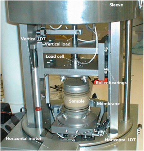
FIGURE 1. UWA simple shear apparatus.
2.2 Material and specimens preparation
Testing was conducted on four reconstituted clay specimens with high plasticity. Onsoy clay samples were retrieved from a depth of 3–4 m in a test pit in Onsoy, Norway. Brunei clay samples were provided in the form of tube samples recovered over depths between 5 m and 120 m from a single borehole at the site. Bayswater clay was obtained using an excavator from a depth of 4 m–4.5 m in Perth, Australia. New Kaolin clay is artificial clay currently used in UWA instead of the UWA Kaolin used previously (Lehane et al., 2009; Richardson et al., 2009; Chow et al., 2014; Mahmoodzadeh & Randolph, 2014). The characterizations of the four clays are listed in Table 1, and the properties of old Kaolin clay are also given.
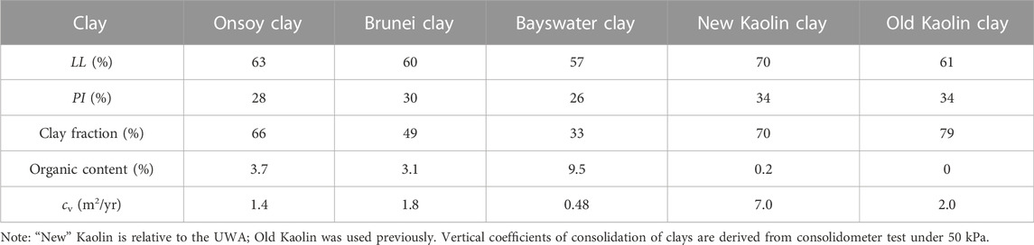
TABLE 1. Summary of soil parameters.
When preparing the clay slurries, all debris, shells or other contaminants larger than 0.5 mm were first removed. The clay was then placed in a high-capacity mixer and mixed to a water content of approximately 1.75 to 2.0 times the liquid limit. After several hours of mixing to achieve a consistent slurry, the samples were transferred to large “Nally” bins, where they were repeatedly remixed with a hand mixer to maintain sample uniformity. The clay slurry was poured into 90 mm diameter tubes and consolidated in stages to a final vertical effective stress that was usually 3–5 kPa smaller than the test pressure. The samples were then extruded from the consolidation tubes and trimmed to test specimens using the thin-walled sample cutter. The specimens were 72 mm in diameter, and the heights after consolidation are shown in Table 2.
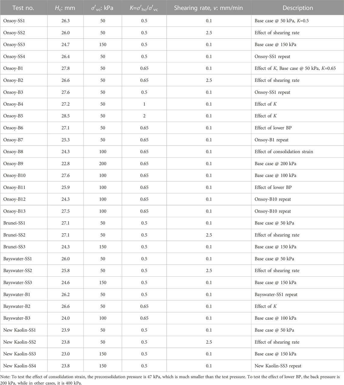
TABLE 2. Testing program.
2.3 Testing program
The testing program is shown in Table 2. It consists of 17 tests for Onsoy clay, 3 tests for Brunei clay, 6 tests for Bayswater clay, and 4 tests for new Kaolin clay. Each clay shearing test was conducted in the undrained condition to investigate the effect of shearing rate, consolidation stress, lateral stress ratio K, back pressure, and consolidation strain in the tube. According to Table 1, the four high-plasticity clays have a wide range of consolidation coefficients. Many tests are repeated.
3 Undrained shear test results
The height of specimens, excess pore pressure ratios, and lateral stress ratios, all at failure, and the undrained strength ratios obtained in simple shear tests are listed in Table 3.
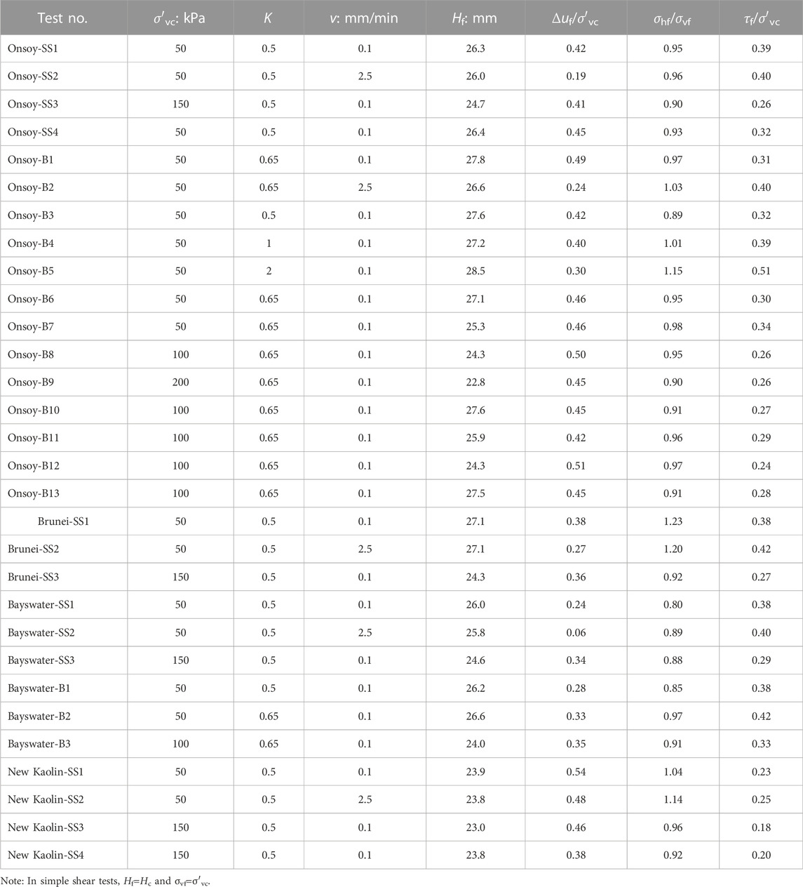
TABLE 3. Summary of test results.
3.1 Undrained strength
There was no apparent effect of lower back pressure (BP) and consolidation strain on undrained strength, so these tests were taken as repeat tests of the base case. The undrained strengths of all repeat tests are plotted in Figure 2 with respect to vertical consolidation stress. There is a certain range of undrained strength, which may be due to a lack of uniformity of samples and test operations or uncertainty during undrained shearing. However, there is a good response trend when plotting the relationship between undrained strength and excess pore pressure at failure (Figure 3). The increase in excess pore pressure at failure causes a decrease in undrained strength, which is in good agreement with the principle of effective stress. That is to say, the uncertainty of the strength during undrained shearing becomes certain in the effective stress analysis.
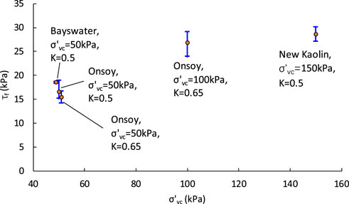
FIGURE 2. Undrained strength vs. vertical consolidation stress.
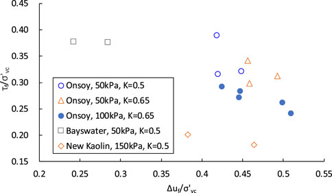
FIGURE 3. Variation in undrained strength ratio with excess pore pressure ratio at failure.
Figure 4 shows variation in the undrained strength ratio with vertical consolidation stress. The undrained strength ratio varies between 0.18 and 0.42, which is much larger than the actual value range (Jamiolkowski et al. (1985)). The undrained strength ratio decreases with the increase of vertical consolidation stress. From the Jurgenson–Rutledge hypothesis (Rutledge, 1947), the undrained strength ratio is constant for clay soils, assuming the curve of ef-logσvc is parallel to the curve of ef-log(σ1-σ3)f. Lehane et al. (2009) suggested that the undrained strength ratio may reduce slightly with an increase in effective stress level when the vertical effective stress is larger than 100 kPa. Boukpeti & White (2017) gave a non-linear failure envelope of the power law relationship when effective normal stress is smaller than 10 kPa. Therefore, for a large range of stress, the failure envelope would be non-linear, which means there is a tiny cohesion of about 5 kPa for normally consolidated clay while applying the linear Mohr–Coulomb criterion. That is why the undrained strength ratio decreases with vertical consolidation stress in low stress and only slightly reduces or is nearly constant in moderate or high stress.
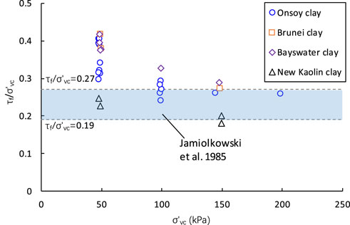
FIGURE 4. Variation in undrained strength ratio with vertical consolidation stress.
The undrained strength ratio versus the lateral stress ratio K for Onsoy clay is shown in Figure 5. There is a clear increasing trend of τf/σ′vc vs. K. For a certain vertical consolidation stress, the larger the K value, the lower the void ratio or water content. According to the shear strength theory developed by Hvorslev (1960), the strength at failure was a function of the effective normal stress and the void ratio at failure. Therefore, the increase in K leads to a decrease in the void ratio, resulting in an increase in undrained strength. The effect of K on effective stress will be discussed below.
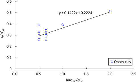
FIGURE 5. Variation in undrained strength ratio with lateral stress ratio.
Lehane and Jardine (1992) ascribed a moderate positive rate effect to viscous phenomena combined with variable degrees of particle sorting within the shear zone. Lehane et al. (2009) suggested that viscous effects dominate under the fully undrained condition, which is beneficial to resistance and strength. An overall increase in undrained strength with shearing rate was observed for the four clays (Figure 6). Although the undrained strength ratio at 0.1 mm/min for each material varies to some degree, the average values of each specimen do not change the overall trend of increasing. The effect of shearing rate on excess pore pressure is much more significant than undrained strength and will be discussed below. It appears that the gain of undrained strength for low permeability clay is mainly caused by smaller excess pore pressure than viscous effects due to a faster shearing rate.
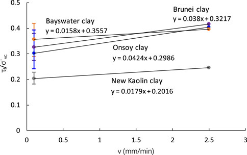
FIGURE 6. Variation in undrained strength ratio with shearing rate.
3.2 Excess pore pressure
Variation in excess pore pressure ratio at failure with shearing rate is shown in Figure 7. Excess pore pressure decreases with strain rate after the strain is larger than 5% (Richardson & Whitman, 1963). At the fast shearing rate of 2.5 mm/min, the shear strain reaches 30% in only 3 min, and the specimen has already failed. Compared to the slow shearing of 0.1 mm/min, there is not enough time for the pore pressure to increase fully. However, there is no noticeable change between the slow and fast rates for new Kaolin clay. This is because the new Kaolin’s coefficient of consolidation (7.0 m2/yr) is much larger than the coefficients of the three other clays (0.48–1.8 m2/yr), and the excess pore pressure is not only related to the shearing rate but also to the coefficient of consolidation.
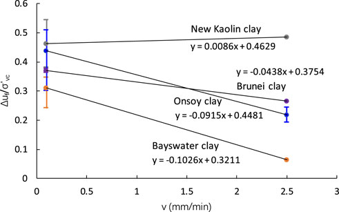
FIGURE 7. Variation in excess pore pressure ratio at failure with shearing rate.
To find the effect of the consolidation coefficient, the curves of excess pore pressure versus shear strain for the four clays are plotted together, as shown in Figure 8. They are all at an identical shearing rate of 2.5 mm/min, and the order of the coefficient of consolidation is new Kaolin>Brunei≈Onsoy>Bayswater (Table 1). After the shear strain becomes greater than 10%, the excess pore pressure of the new Kaolin is greater than that of other clays, Brunei’s is close to Onsoy’s, and Bayswater’s is the smallest. There is a good agreement between excess pore pressure and the coefficient of consolidation. In other words, the clay with the larger coefficient of consolidation is more likely to generate excess pore pressure under undrained shearing.
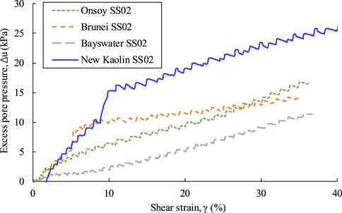
FIGURE 8. Excess pore pressure ratio plotted against shear strain at a shearing rate of 2.5 mm/min.
The excess pore pressure ratio at failure decreases with the increase in specimen height, as displayed in Figure 9. In the triaxial test, excess pore pressure was measured with different height-to-diameter ratios, showing that the larger the specimen height, the smaller the pore pressure (Muraro & Jommi, 2021). The specimens in this investigation, contained by a flexible membrane and subjected to cell pressure, are subject to conditions similar to those of the triaxial test, and the corresponding excess pore pressure changes with the height of the specimen while shearing is also consistent.
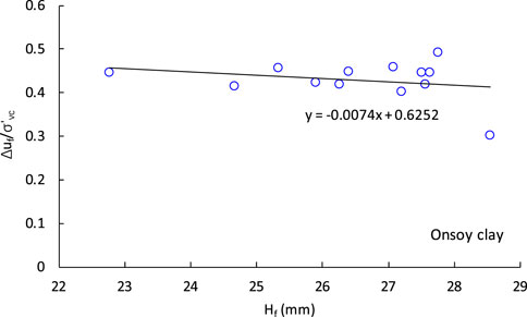
FIGURE 9. Variation in excess pore pressure ratio with specimen height, both at failure.
A soft clay sample may possibly contain a combination of both a discrete diagonal shear plane and the conventional type of simple shear deformation (Joer et al., 2010). In the flexible boundary, diagonal shear planes are formed through the specimen in the Berkeley simple shear device, generally from the back of the top platen to the top of the front of the bottom platen, and a visible shear plane forms at large strain greater than about 15% (Sharma et al., 2017). Figure 10 shows photographs of typical failure planes in a Berkeley simple shear device for each clay, with the same shear failure mode suggested by Budhu (1984) and Reyno et al. (2005). Shearing occurred in a shear band of thickness that resulted in the generation of excess pore pressure while neglecting possible pore pressure generation outside the shear band in the direct shear test (Boukpeti & White, 2017). For the simple shear test, the regions outside the shear plane still undergo shear deformation, and the excess pore pressure cannot be ignored, but due to stress concentration, the excess pore pressure of the shear plane is much larger than other regions, especially when the specimen is close to failure. The shear band thickness of clayey soil was 2–8 mm after shearing was completed, which is independent of the height and diameter of the specimen (Hicher et al., 1994; Gylland et al., 2014), while the shear band thickness decreases with the shearing rate (Jostad et al., 2006; Gylland et al., 2014). Therefore, the diameter of the specimen has little effect on the excess pore pressure, and the larger the height of the specimen, the smaller the excess pore pressure due to diffusion and the averaging effect.
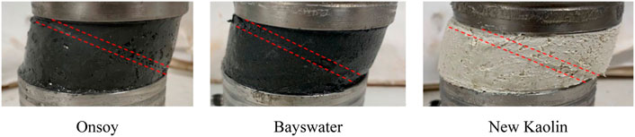
FIGURE 10. Photographs of typical failure planes in a Berkeley simple shear device.
There is a definite decreasing trend in the ratio of excess pore pressure versus lateral stress shown in Figure 11. The decrease in excess pore pressure causes the effective stress to increase, which will contribute to the undrained strength. In addition to the smaller void ratio at failure induced by the increase of lateral stress ratio discussed above, the gain in effective stress is another factor to improve undrained strength, according to the shear strength theory developed by Hvorslev (1960). For Onsoy clay, the relationship between excess pore pressure and lateral stress ratio can be approximated by the following equation:
where K is the lateral stress ratio, and
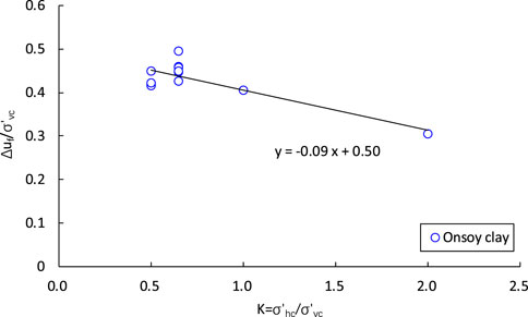
FIGURE 11. Variation in excess pore pressure to lateral stress ratio at failure.
4 Formula for undrained shear strength
The above analysis shows that the lower the shearing rate, the larger the coefficient of consolidation, and the smaller the specimen height, the larger the excess pore pressure. Therefore, similar to the normalization of penetrometer velocity proposed by Finnie & Randolph (1994), the normalized shearing rate in the simple shear test can be established as follows:
where v is the shearing rate, expressed in mm/min, Hf is the height of the specimen at failure or after consolidation, and cv is the vertical coefficient of consolidation.
Figure 11 shows little difference in excess pore pressure ratio between K=0.5 and 0.65, so these data can be plotted together as K=0.575. The relationship between excess pore pressure and normalized shearing rate for four clays tested with a K value of 0.5 and 0.65 is plotted in Figure 12. The excess pore pressure ratio and the normalized shearing rate have a good linear decreasing relationship in the semi-logarithmic coordinate.
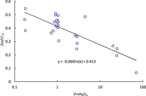
FIGURE 12. Variation in excess pore pressure and normalized shearing rate ratio at failure.
The excess pore pressure ratio is given by
Combining Eq. 1 and Eq. 3, where the K value of Eq. 3 is 0.575, the lateral stress ratio can be taken into account in the equation, and the excess pore pressure ratio may be written as
For an undrained simple shear test, taking Hf=25 mm and v=0.1 mm/min, Eq. 4 becomes
where cv is expressed in m2/yr.
For soil in the field, the lateral stress ratio K can be calculated by Eq. 6, proposed by Mayne and Kulhawy (1982).
where
The undrained strength depends on the amount of effective normal stress or excess pore pressure generated during shearing. This may be expressed as
where
Eq. 5 is suitable for normally consolidated or slightly over-consolidated clay, so Eq. 7, based on Eq. 5, is also applicable in the same clay but not for medium or strong over-consolidated clay.
An alternative interpretation of the simple shear test that considers the diagonal failure plane rather than the horizontal plane is given by Joer et al. (2010). Effective parameters on the horizontal plane can be deduced according to the traditional interpretation of horizontal failure mode (Table 4). Figure 13 gives the typical stress paths and failure envelopes on the horizontal and failure planes, respectively, which are both based on undrained simple shear tests. The failure points in the diagram are determined by the shear stress, normal stress, and pore pressure at the point of peak shear stress. The failure envelopes both show a good linear relationship, while the envelope of the failure plane is slightly more linear than that of the horizontal plane. As shown in Table 4, cohesion on the horizontal and failure planes is very close for each clay, and the friction angle on the horizontal plane is smaller than that on the failure plane.
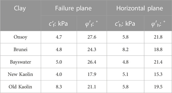
TABLE 4. Summary of strength parameters based on effective stresses.
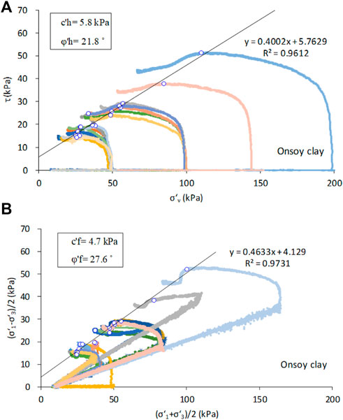
FIGURE 13. Stress path and failure envelope-based effective stresses for Onsoy clay: (A) horizontal plane, (B) failure plane.
The strength parameters of the failure plane based on effective stresses can be obtained by various methods, such as the CU and CD triaxial tests, the drained direct shear test, and the simple shear test. Effective strength parameters must be used when applying Eqs 5, 7 to predict undrained strength. It is possible to deduce effective parameters of the horizontal plane from failure plane parameters. The comparisons of effective strength parameters between the horizontal and failure planes are shown in Figure 14. The relationships of cohesion and friction angle between different planes are as follows:
where
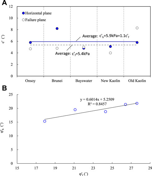
FIGURE 14. Effective strength parameter comparison between horizontal and failure planes: (A) cohesion, (B) friction angle.
5 Verification of undrained strength
5.1 Reconstituted clay
Including the data of the old Kaolin clay used in UWA previously (Lehane et al., 2009), the undrained strength of five clays was compared with the measurement and prediction data from Eqs 4, 7, shown in Figure 15A. In addition, Leonards’ method was compared in Figure 15B. Leonards (1962) gave Eq. 10 to estimate undrained strength.
where Af is the pore pressure parameter, and its value is 0.7–1.3 for normally consolidated clays.
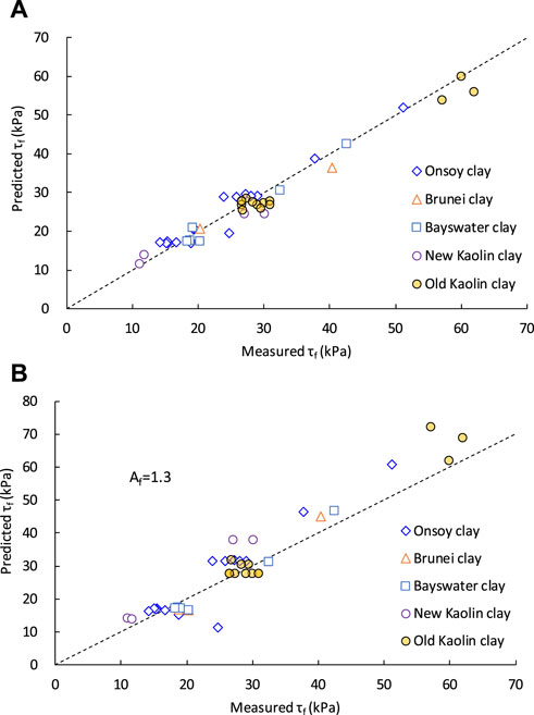
FIGURE 15. Comparison between predicted and measured undrained strength for reconstituted clay: (A) method of Eqs 4, 7, (B) method of Leonards (1962).
Figure 15A shows good agreement between predicted and measured undrained τf values, including those of the old Kaolin clay, which is not referred to in the developing formula. There is a slightly higher calculated undrained strength when using Leonards’ method with the Af value of the upper limit in Eq. 10. The lower the Af value, the higher the strength. It is difficult to determine the pore pressure parameter properly.
Jamiolkowski et al. (1985) suggested that
Figure 4 shows the normalized undrained strength of Eq. 11 with the measured values for each clay. There is an obvious decreasing trend of undrained strength ratio versus vertical consolidation stress, while a trend is not clear in the Jamiolkowski equation. Jamiolkowski’s strength ratio is the lower limit of the measured values. From Eqs 7, 10, the undrained strength ratio decreases with increasing vertical consolidation stress due to the existence of clay cohesion. If the cohesion is equal to 0, the undrained strength ratio is constant and would not change with the level of stress. Cohesion can be neglected for high stress levels, and the undrained strength ratio is nearly constant.
5.2 Intact Onsoy clay
According to the reference of the NGI research report (2019) and Gundersen et al. (2019), the property profiles of clay at the Onsoy site are listed in Figure 16A. The OCR value of Onsoy clay is 1.3–1.9, and the cv value is 3–11 m2/yr with a soil depth of 3–20 m. Therefore, intact Onsoy clay is slightly overconsolidated clay with an average OCR of 1.5 and has a larger coefficient of consolidation than reconstituted Onsoy clay. Soil disturbance delays the consolidation and hence reduces the coefficients of consolidation of both normally consolidated and overconsolidated clays (U.S. Navy, 1982). Holtz et al. (2011) included lightly overconsolidated deposits with an OCR < 2 in the category of normally consolidated clays. Representative values of the friction angle and cohesion are φ′f=30° and c’f=5 kPa, respectively (Gundersen et al., 2019). The predictions given by Eqs 5, 7 are compared with different types of measured undrained shear strength in Figure 16B.
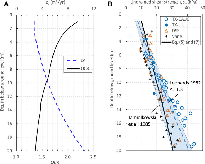
FIGURE 16. Intact Onsoy clay: (A) OCR and cv profiles, (B) comparison between predicted and measured undrained strength.
In direct simple shear (DSS) tests, the clay specimens were consolidated to what was believed to be a low estimate of the preconsolidation stress (approximately 75%–80%) and then unloaded to the estimated in situ effective vertical stress before shearing. This method was used to counteract the negative effect of stress release and other disturbance effects during sampling and extrusion (ISO 19901-8, 2015). UU triaxial tests have been performed on intact material. All consolidated undrained triaxial compression (CAUC) tests were consolidated to a best estimate of the in-situ stress condition with a K0 value of 0.6 on the soft clay from the Onsoy site. The vane test is usually considered to give the best result of the undrained strength of clay.
The undrained strength of DSS tests is in the empirical range of Jamiolkowski, which is very close to UU test results and slightly lower than the strength found using CAUC tests, especially below a depth of 10 m. The undrained strength of DSS tests at a depth of 0–9 m is essentially the same as the vane strength, but its strength below 9 m is slightly higher than the vane strength. The predicted undrained strength from Eqs 5, 7 for intact Onsoy clay has a good agreement with vane and DSS test results, while the predicted strength using Leonards’ method is at the upper limit of that found using the DSS tests. However, in Figure 16B, the value of Af is the upper limit, which leads to the smallest undrained strength. For intact clay, obtaining good estimates of the pore pressure parameter Af is often difficult because that parameter is very sensitive to sample disturbance.
6 Conclusion
The undrained strength of clay determined by the simple shear test is related to shearing rate v, coefficient of consolidation cv, the height of specimen Hf, consolidation stress σ′vc and lateral stress ratio K. Although there is some uncertainty for undrained strength, it could become much more certain with an effective stress analysis. A normalized shearing rate V=vHf/cv is suggested to develop the relationship with excess pore pressure. Based on the Mohr–Coulomb failure criterion, undrained strength can be calculated from strength parameters in terms of effective stress. The equations developed with high plasticity clays are suitable for normally consolidated and slightly overconsolidated clays. In addition, the failure mode of specimens in a Berkeley simple shear device is a diagonal failure plane instead of a horizontal plane. Meanwhile, an empirical relationship of strength parameters on different planes is established.
Data availability statement
The original contributions presented in the study are included in the article/Supplementary material; further inquiries can be directed to the corresponding author.
Author contributions
Methodology, BH and SC; investigation and experiment, SC and JL; resources, JL and KW; writing—original draft preparation, BH and KW; writing—review and editing, SC. All authors have read and agreed to the published version of the manuscript.
Funding
The work presented in this paper was finished at the University of Western Australia, where the first author engaged in CSC post-doctoral research work (CSC grant No. 201906275010).
Acknowledgments
The authors express sincere thanks to Professor Phil Watson, who leads the Shell Chair in Offshore Engineering research team and supported the simple shear testing at the University of Western Australia. The second author also thanks the State Key Laboratory of Subtropical Building Science (Grant No. 2018ZB08). The work is also supported by Undergraduate Online Courses Committee of University in Guangdong Province (Grant No. 2022ZXKC437).
Conflict of interest
The authors declare that the research was conducted in the absence of any commercial or financial relationships that could be construed as a potential conflict of interest.
Publisher’s note
All claims expressed in this article are solely those of the authors and do not necessarily represent those of their affiliated organizations or those of the publisher, the editors, and the reviewers. Any product that may be evaluated in this article, or claim that may be made by its manufacturer, is not guaranteed or endorsed by the publisher.
References
Acharya, B., and Airey, D. (2017). “Effect of specimen confinement method on simple shear test of clay,” in Advances in laboratory testing and modelling of soils and shales (Cham, Switzerland: Springer), 247–254.
Airey, D. W., and Wood, D. M. (1987). An evaluation of direct simple shear tests on clay. Géotechnique 37 (1), 25–35. doi:10.1680/geot.1987.37.1.25
Atkinson, J. H., Lau, W. H. W., and Powell, J. J. M. (1991). Measurement of soil strength in simple shear tests. Can. Geotechnical J. 28 (2), 255–262. doi:10.1139/t91-031
Bjerrum, L., and Landva, A. (1966). Direct simple-shear tests on a Norwegian quick clay. Geotechnique 16 (1), 1–20. doi:10.1680/geot.1966.16.1.1
Bjerrum, L. (1973),.Problems of soil mechanics and construction on soft clays, Proceedings of the 8th international conference on soil mechanics and foundation engineering, Moscow, Russia, August 1973, 3, 111–159.
Boukpeti, N., and White, D. J. (2017). Interface shear box tests for assessing axial pipe–soil resistance. Géotechnique 67 (1), 18–30. doi:10.1680/jgeot.15.p.112
Budhu, M. (1985). Lateral stresses observed in two simple shear apparatus. J. Geotechnical Eng. 111 (6), 698–711. doi:10.1061/(asce)0733-9410(1985)111:6(698)
Budhu, M. (1984). Nonuniformities imposed by simple shear apparatus. Can. Geotechnical J. 21 (1), 125–137. doi:10.1139/t84-010
Chow, S. H., O'loughlin, C. D., and Randolph, M. F. (2014). Soil strength estimation and pore pressure dissipation for free-fall piezocone in soft clay. Géotechnique 64 (10), 817–827. doi:10.1680/geot.14.p.107
Dyvik, R., Berre, T., Lacasse, S., and Raadim, B. (1987). Comparison of truly undrained and constant volume direct simple shear tests. Geotechnique 37 (1), 3–10. doi:10.1680/geot.1987.37.1.3
Finnie, I. M. S., and Randolph, M. F. (1994). “Punch-through and liquefaction induced failure of shallow foundations on calcareous sediments,” in Proceedings of the international conference on behaviour of offshore structures, Boston, MA, USA, July 1994, 217–230.
Gundersen, A., Hansen, R., Lunne, T., L Heureux, J. S., Strandvik, S. O., O. Strandvik, S., et al. (2019). Characterization and engineering properties of the NGTS Onsøy soft clay site. AIMS Geosci. 5 (3), 665–703. doi:10.3934/geosci.2019.3.665
Gylland, A. S., Jostad, H. P., and Nordal, S. (2014). Experimental study of strain localization in sensitive clays. Acta Geotech. 9 (2), 227–240. doi:10.1007/s11440-013-0217-8
Hicher, P. Y., Wahyudi, H., and Tessier, D. (1994). Microstructural analysis of strain localisation in clay. Comput. Geotechnics 16 (3), 205–222. doi:10.1016/0266-352x(94)90002-7
Holtz, R. D., Kovacs, W. D., and Sheahan, T. C. (2011). An introduction to geotechnical engineering. London, UK: Pearson.
Hvorslev, H. J. (1960). “Physical components of the shear strength of cohesive soils,” in Proceedings of the Research Conference on Shear Strength of Cohesive Soils ASCE, Boulder, CO, USA, June 1960, 169–273.
Jamiolkoswski, M., Ladd, C. C., Germaine, J. T., and Lancellotta, R. (1985). “New developments in field and laboratory testing of soils,” in Proceedings of the 10th International Conference on Soil Mechanics and Foundation Engineering, San Francisco, CA, USA, 57–153.1,
Joer, H. A., Erbrich, C. T., and Sharma, S. S. (2010). “A new interpretation of the simple shear test,” in Proceedings of the 2nd International. Symp. On Frontiers in Offshore Geotechnics, Perth, Australia, November 2010.
Jostad, H. P., Andresen, L., and Thakur, V. (2006). Calculation of shear band thickness in sensitive clays. 6th Numer. methods geotechnical Eng. 1, 27–32.
Ladd, C. C., and Foott, R. (1974). New design procedure for stability of soft clays. J. Geotechnical Geoenvironmental Eng. 100 (7), 763–786. doi:10.1061/ajgeb6.0000066
Lehane, B. M., and Jardine, R. J. (1992). Residual strength characteristics of Bothkennar clay. Géotechnique 42 (2), 363–367. doi:10.1680/geot.1992.42.2.363
Lehane, B. M., O'loughlin, C. D., Gaudin, C., and Randolph, M. F. (2009). Rate effects on penetrometer resistance in kaolin. Géotechnique 59 (1), 41–52. doi:10.1680/geot.2007.00072
Mahmoodzadeh, H., and Randolph, M. F. (2014). Penetrometer testing: Effect of partial consolidation on subsequent dissipation response. J. Geotechnical Geoenvironmental Eng. 140 (6), 04014022. doi:10.1061/(asce)gt.1943-5606.0001114
Mayne, P. W. (1985). A review of undrained strength in direct simple shear. Soils Found. 25 (3), 64–72. doi:10.3208/sandf1972.25.3_64
Mayne, P. W., and Kulhawy, F. H. (1982). Ko-OCR relationships in soil. J. Geotechnical Eng. Div. 108 (6), 851–872. doi:10.1061/ajgeb6.0001306
Muraro, S., and Jommi, C. (2021). Experimental determination of the shear strength of peat from standard undrained triaxial tests: Correcting for the effects of end restraint. Géotechnique 71 (1), 76–87. doi:10.1680/jgeot.18.p.346
U.S. Navy (1982). Soil mechanics – design manual 7.1, naval facilities engineering command. Washington, DC, USA: U.S. Government Printing Office.
NGI research report (2019). “Norwegian GeoTest sites—field and laboratory test results from NGTS soft clay site—onsøy,”. Report No: 20160154-10-R (Sognsveien, Norway: Norwegian geotechnical institute).
Prevost, J. H., and Høeg, K. (1976). Reanalysis of simple shear soil testing. Can. Geotechnical J. 13 (4), 418–429. doi:10.1139/t76-042
Randolph, M. F., and Wroth, C. P. (1981). Application of the failure state in undrained simple shear to the shaft capacity of driven piles. Geotechnique 31 (1), 143–157. doi:10.1680/geot.1981.31.1.143
Randolph, M., and Gourvenec, S. (2017). Offshore geotechnical engineering. Boca Raton, FL, USA: CRC Press.
Rau, G. A. (1999). Evaluation of strength degradation in seismic loading of Holocene Bay mud from Marin County, California. PhD Thesis (Berkeley, CA, USA: University of California).
Reyno, A. J., Airey, D., and Taiebat, H. A. (2005). “Influence of height and boundary conditions in simple shear tests,” in International symposium on Frontiers in offshore geotechnics (Boca Raton, FL, USA: Taylor & Francis/Balkema).
Richardson, A. M., and Whitman, R. V. (1963). Effect of strain-rate upon undrained shear resistance of a saturated remoulded fat clay. Geotechnique 13 (4), 310–324. doi:10.1680/geot.1963.13.4.310
Richardson, M. D., O’Loughlin, C. D., Randolph, M. F., and Gaudin, C. (2009). Setup following installation of dynamic anchors in normally consolidated clay. J. Geotechnical Geoenvironmental Eng. 135 (4), 487–496. doi:10.1061/(asce)1090-0241(2009)135:4(487)
Rutledge, P. C. (1947). Review of ‘Cooperative triaxial shear research program of the Corps of Engineers’. Vicksburg, MS, USA: USAE Waterways Experiment Station.
Sharma, S. S., Ramsey, N., Lee, F., and Bhattarai, B. N. (2017). Challenges in assessing the shear strength of offshore sediments using simple shear tests. Geotech. Front. 2017, 327–336.
Verma, P., and Wijewickreme, D. (2020). Effect of different modes of lateral boundary constraints of the direct simple shear (DSS) device under monotonic and cyclic shear loading. Geotechnical Test. J. 43 (4), 20180357–20181070. doi:10.1520/gtj20180357
Wood, D. M., Drescher, A., and Budhu, M. (1979). On the determination of stress state in the simple shear apparatus. Geotechnical Test. J. 2 (4), 211–222. doi:10.1520/gtj10460j
Keywords: undrained shear strength, simple shear, shearing rate, excess pore pressure, clay
Citation: Huang B, Cai S, Li J, Wu K and Yang W (2023) Undrained strength of clay determined from simple shear test. Front. Earth Sci. 10:1098846. doi: 10.3389/feart.2022.1098846
Received: 15 November 2022; Accepted: 12 December 2022;
Published: 04 January 2023.
Edited by:
Guang-Liang Feng, Institute of Rock and Soil Mechanics (CAS), ChinaReviewed by:
Yong Wen, Zhongkai University of Agriculture and Engineering, ChinaFu-Quan Chen, Fuzhou University, China
Copyright © 2023 Huang, Cai, Li, Wu and Yang. This is an open-access article distributed under the terms of the Creative Commons Attribution License (CC BY). The use, distribution or reproduction in other forums is permitted, provided the original author(s) and the copyright owner(s) are credited and that the original publication in this journal is cited, in accordance with accepted academic practice. No use, distribution or reproduction is permitted which does not comply with these terms.
*Correspondence: Shiqian Cai, Y3VjdW1iZXJoYkBvdXRsb29rLmNvbQ==