 Jinshan Sun
 Yongsheng Jia1,2
 Yingkang Yao
- 1State Key Laboratory of Precision Blasting, Jianghan University, Wuhan, China
- 2Hubei Key Laboratory of Blasting Engineering, Jianghan University, Wuhan, China
Seismic waves induced by blasting can cause damage to slope rock masses and thus lower the stability of the slope. The vibration standards of many countries do not specify the allowable blasting vibration velocity for slope rock masses. “Blasting Safety Regulations” (GB 6722-2014) in China recommends the allowable blasting vibration velocity of slope rock masses. However, the strength of rock mass and geometric characteristics of slope are not considered in the criterion. Therefore, based on the wave equation of Rayleigh wave, the mathematical relationship between the additional dynamic stress of the rock mass near the slope surface and the peak particle velocity (PPV) on the ground is analyzed. Under the control conditions that no tensile and shear damage occur in the slope, a calculation method of allowable blasting vibration based on a simple slope model is proposed, in which the strength of rock mass and the angle of the slope are considered. The theoretical basis of the proposed method is verified by numerical experiments. Based on the field test results of the slope of Xiaowan Hydropower Station, the proposed method was verified further. The damage control target of the rock mass determined by the proposed method was in good agreement with the actual damage detection result.
1 Introduction
Blasting is used widely in rock excavation of foundations, highway, railway, and mining. The most common types of blasting damage are caused by ground vibration. In high rock slope engineering, foundation vibration can induce additional dynamic stress, which may damage rock mass and affect slope stability.
In blasting assessment, peak particle velocity (PPV) is one of the widely used indexes of vibration damage to structures or geotechnical features. To control blasting vibration and damage, many countries have developed separate ground vibration standards such as China (Chinese National Standard, 2015) (GB 6722), United States (United States. Bureau of MinesSiskind, 1980; Rosenthal and Morlock, 1987; Quagliata et al., 2018) (OSMRE, USBM RI 8507, FTA), Australia (AS 2187.2), Swiss (SN 640 312a), Britain (BS 7385), Germany (DIN 4150), New Zealand (NZS 4403), Brazil (NBR 9653), France (GFEE), Sweden (Harmoniska Svangningar), Indian (CMRI), and Indonesian (SNI 7571) (Earth Production China Limited, 2020). In addition, there is an International Standards Organization standard (ISO 4866) (Skipp, 1998). However, there is no acceptable blasting vibration limit for rock slopes in these standards.
Many scholars have studied the blasting vibration limit for rock slopes. Savely (1986) proposed the allowable peak particle vibration velocity of slope based on the investigation results of several mine slopes. The safety blasting vibration velocity recommended by Changsha Research Institute of Mining and Metallurgy (Luo et al., 2010) is shown in Table 1. Safety Standards of Blasting Vibration for Slopes of Several Hydropower Projects in China (Lu et al., 2012) are shown in Table 2. Based on a large number of research results, GB 6722 (Chinese National Standard, 2015) stipulates that the safety vibration velocity of the permanent rock slope is 5–15 cm/s (Table 3), and points out that the determination of the blasting vibration limit of the rock slope should comprehensively consider the importance of the slope, the initial stability of the slope, the support condition and the excavation height, etc., but it does not explain how to comprehensively consider them.
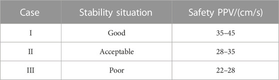
TABLE 1. Safety blasting vibration velocity for open mines (Luo et al., 2010).
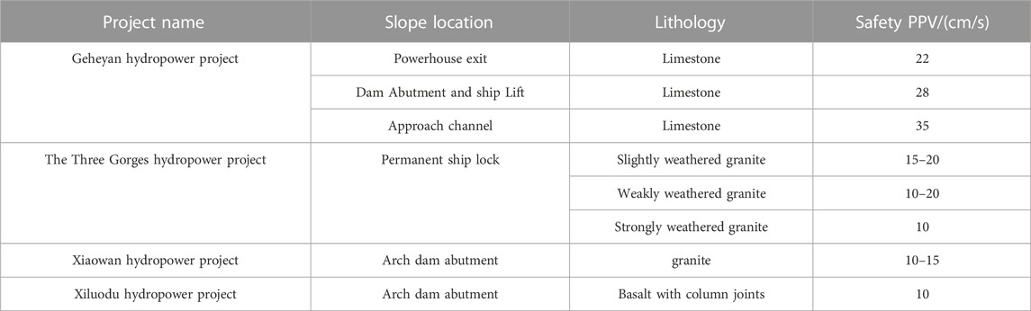
TABLE 2. Safety standard of blasting vibration for slopes of several hydropower projects in China.

TABLE 3. Safety criterion of blasting vibration for rock slope in regulations[1].
At present, the allowable blasting vibration velocity in engineering practice is often determined by engineering analogy, which lacks the corresponding theoretical basis. At the same time, it is not reasonable to choose the same vibration velocity control standard for different forms of slopes and rock masses of different quality. However, there is still a lack of research results on how to consider the difference of rock mass level and the geometric shape of the slope. Therefore, taking the damage control of the rock mass as the goal and considering the geological conditions of the slope, this paper studies the safe vibration velocity of rock mass of slopes through the analysis of the propagation characteristics of blasting seismic waves.
Rock slopes include homogeneous slopes and slopes controlled by weak structural planes. The characteristics of slopes controlled by weak structural planes are more complicated, and their allowable vibration velocities need to be analyzed separately. Therefore, this paper mainly discusses the allowable vibration velocities of the homogeneous fractured rock mass in the shallow layer of slope.
2 Dynamic stress and particle vibration velocity induced by Rayleigh waves
Blasting seismic waves mainly include body waves and surface waves (shown in Figure 1). Body waves include longitudinal waves and shear waves, and surface waves include Rayleigh waves (R waves) and Love waves (L waves), etc. The body wave mainly has a strong effect on the rock and soil masses near the blast hole, while the surface wave mainly affects the rock and soil material far away from the blast hole. Under the plane strain assumption, the dynamic response of rock and soil materials near the blast hole under the action of cylindrical wave and plane wave can be obtained analytically, and there is a theoretical conversion relationship between the particle velocity and the additional dynamic stress. In the far area of the blast hole, the dynamic response of the geotechnical material is more complicated because it is in a semi-infinite space. The relationship between particle velocity and additional dynamic stress has not been reported.
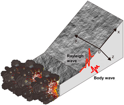
FIGURE 1. Blasting seismic wave in a slope.
In the artificial slope shown in Figure 1, considering that the surface wave mainly propagates along the surface, the large-scale rock and soil mass on the propagation path of the seismic wave is taken as the analysis area, which is simplified as a semi-infinite space system. In order to obtain the analytical solution of the dynamic problem, the geotechnical material is assumed to be isotropic homogeneous.
In a semi-infinite elastic space, the plane wave equation in an isotropic elastic solid is:
where, ux is the dynamic displacement of the particle of the slope along the slope direction (x direction), uz is the dynamic displacement of the particle perpendicular to the slope direction (z direction). λ is the Lame constant of geotechnical materials, G is the shear modulus, ρ is the density,
To solve the wave equation, the displacement potential function
where, A and B are the amplitude of the displacement potential function, CR is the wave velocity of the Rayleigh wave. k, r and s are:
where, CP is the wave velocity of P wave, CS is the wave velocity of S wave,
The approximate solution of CR is (Sargent Rinehart, 1975):
r and s can be obtained:
ux and uz can be expressed by the displacement potential functions as follows:
The general solutions of wave equations are:
According to Hooke’s Law, the dynamic stress of geotechnical material caused by R wave can be expressed as:
where, μ is the Lame constant of geotechnical materials.
Substituting Eq. 11 into Eq. 12 and taking the real part, the dynamic stress at the particle is:
The particle velocity in the x and z direction is:
Substituting Eq. 11 into Eq. 14 and taking the real part, the particle velocity is obtained as follows:
3 Predictive model of additional dynamic stress expressed by surface vibration velocity
In blasting engineering, the blasting disturbance is mainly evaluated by the peak vibration velocity of ground particles. The amplitudes of vibration velocities in X direction and Z direction at any depth in Eq. 15 are:
Substituting z=0 into Eq. 16, the amplitude of the vibration velocity on the slope is obtained:
According to Eq. 17, the relationship between the peak vibration velocity of the slope and the amplitude of the displacement potential function A can be obtained:
Based on Eqs 13, 18, the additional dynamic stress at any depth caused by the R wave in the slope can be calculated:
Taking the amplitude of stress in Eq. 19, the peak value of additional dynamic stress expressed by the peak particle vibration velocity (PPV) is:
σx、σz and σzx of the geotechnical materials under the slope change with the depth z. It is significant to determine the peak value of the additional dynamic stress and its depth z for the engineering safety rating. To find the depth of peak value of additional dynamic stress, let z=0 or
Solving Eq. 21, the possible depth z of the additional dynamic stress peak is:
Substituting Eq. 22 into Eq. 20, and comparing the peak stresses, it can be found that when σx, σz and σzx reach the peak, the depth is:
Substituting Eq. 23 into Eq.19, the maximum additional dynamic stress in rock mass expressed by the vibration velocity of particle on the slope surface can be obtained.
4 Vibration damage assessment of slope rock mass based on vibration velocity
Generally speaking, the additional dynamic stress produced by blasting seismic waves is relatively weak. However, the special shape of the slope may make the rock mass close to yielding state, and weak dynamic disturbance may cause yield or damage. Therefore, in slopes with the low stability coefficients of landslide, damage caused by blasting must be controlled. In engineering practice, the peak vibration velocity of ground particles is the main indicator of blasting damage. Reducing the peak value of blasting vibration velocity is the main way to reduce the slope disturbance caused by blasting.
4.1 Control of tensile damage along the slope
Equation 22 shows that σx has the largest value at z=0 on the slope surface, which is more likely to cause tensile damage of rock mass. In order to avoid the tensile damage of rock and for the sake of safety, the additional dynamic stress
According to Eq. 20, 24, when there is no dynamic tensile damage in x direction, the peak value of particle vibration velocity in x direction of slope surface should meet the following condition:
4.2 Control of tensile damage in direction perpendicular to slope
Equation 22 shows that σz has the biggest value when z>0 below the slope surface, And the rock mass is under compression. In order to avoid the tensile damage of rock, the additional dynamic stress induced by R wave should meet the following condition:
where, σzi is the initial normal stress in the z direction,
According to Eqs 20, 26, when there is no dynamic tensile damage in z direction, the peak vibration velocity of slope particle should meet the following condition:
The solution of inequation can be obtained by changing the value of z.
4.3 Control of shear damage along the slope
The slope rock mass is subjected to the additional dynamic shear action caused by the R wave, and damage will occur when the sum of the static shear force and the additional dynamic shear force exceeds its shear strength. The direction of the maximum shear stress of the rock mass in a simple slope is parallel to the slope surface. To ensure that there is no shear damage to the rock at depth z, the shear stress should be lower than the shear strength:
where,
where, c is the cohesive force, φ is friction angle.
According to Eqs 19, 28, when there is no dynamic shear damage in the zx plane, the peak vibration velocity of slope particle should satisfy the following requirement:
The solution of inequation can be obtained by changing the value of z.
Combining Eqs 25, 27 and 30, the allowable value of blasting vibration velocity without dynamic damage of slope can be obtained.
5 Model verification and discussion
5.1 Numerical simulation verification
Equation 20 is the basis of vibration damage assessment of slope rock mass and needs to be verified. However, model test cannot simulate the characteristics of wavelength and frequency of blasting seismic wave. It is also difficult to accurately measure the dynamic stress of rock mass in different depths by field experiments. Therefore, numerical model can be adopted to verify the theoretical model.
By using ANSYS/LS-DYNA, a three-dimensional finite element model of R wave propagation is established (Figure 2). The model is a cuboid (400 m×400 m×200 m). The size of element is 10 m×10 m×2 m. In order to generate R waves, a sinusoidal dynamic load Psin (ωt) with uniform distribution is applied on the surface of the model, the action range of which is 10 m×20 m. The horizontal distance between the monitoring point and the vibration source is 150 m. There are two groups of rock mass material parameters and vibration parameters (Table 4) (Jiang et al., 2010; YANG et al., 2011). The uniform pressure P is set as 30 MPa, which is obtained through the superposition of the loading generated from multiple blastholes in bench blasting and it is an empirical value. The values of ω are selected based on some experimental tests.
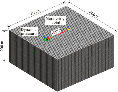
FIGURE 2. Finite element model.
TABLE 4. Calculation parameters.
Figure 3 and Figure 4 present the comparison between the numerical simulation results and theoretical results under two different rock mass parameters. The curves of different variables, which represent theoretical results and numerical simulation results respectively, show the same trend with the increase of the depth z. Furthermore, it can be seen from Figures 3, 4 that the differences between the theoretical results and numerical simulation results are relatively small and acceptable. The theoretical model gives a sufficiently good match against the numerical results and can therefore be used in the further analysis.
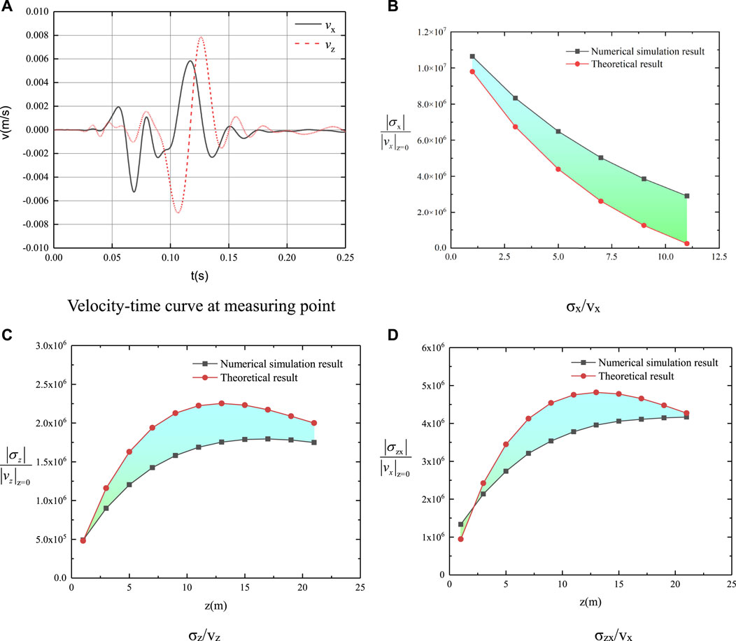
FIGURE 3. Calculation results of case 1 (A) Velocity-time curve at measuring point (B) σx/vx (C) σz/vz (D) σzx/vx.
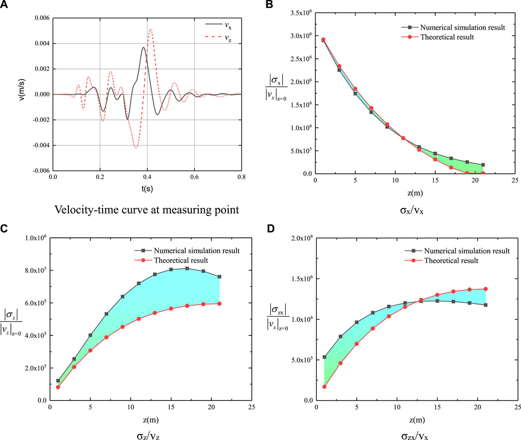
FIGURE 4. Calculation results of case 2 (A) Velocity-time curve at measuring point (B) σx/vx (C) σz/vz (D) σzx/vx.
5.2 Project validation
Xiaowan Hydropower Station is located in Dali Prefecture, Yunnan Province, China. The dam is a parabolic double-curved arch dam with a maximum dam height of 292 m. The abutment slope height is 687 m, and the slope gradient is about 1:0.6 (Figure 5). The rock mass of the slope is mainly gneiss with joints and developed fissures, and the integrity of the rock mass is poor (Table 5). The maximum elevation of the opening line of the right bank slope is 1530 m, and the average excavation slope is 54.2°; the maximum elevation of the opening line of the left bank slope is 1650 m, and the average excavation slope is 55° (Jiang et al., 2010).
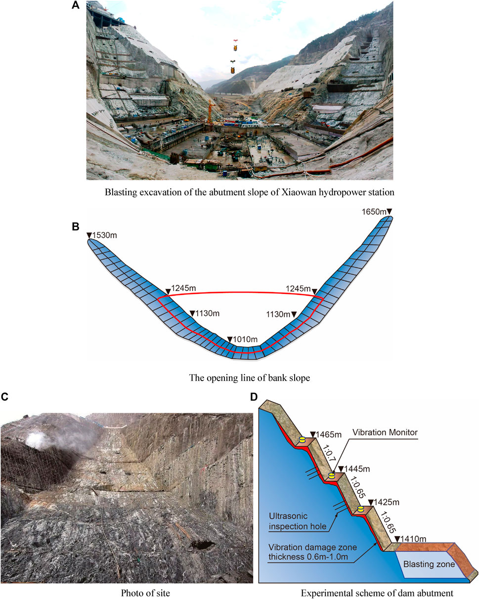
FIGURE 5. Blasting excavation and experimental scheme of dam abutment of Xiaowan Hydropower Station (A) Blasting excavation of the abutment slope of Xiaowan hydropower station (B) The opening line of bank slope (C) Photo of site (D) Experimental scheme of dam abutment.
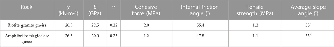
TABLE 5. Physical and mechanical parameters of rock mass (Jiang et al., 2010).
The diameter of the blasthole is 90 mm and 105mm; the hole distance is 2.5–3.5 m; the hole depth is about 10m; the row distance is 2–3 m; the plugging length is 2–2.5 m, and the unit explosive consumption is .5–.6 kg/m3. Excavation below 1,245 m is for dam abutment groove, and the volume of blasting excavation is generally thousands of cubic meters. When the elevation is 1245–1315 m, the blasting excavation volume is greater than 20000 m3. The blasting excavation volume above the elevation of 1315 m is generally less than 1000 m3 (Liu et al., 2007).
Assuming the allowable relaxation depth of the slope after blasting is 1m, that is, the stress of the rock mass at z>1 m should be lower than the tensile or shear strength. According to the geometric parameters of the slope, parameters in Table 5 and the conditions of z>1m, the vibration velocity control values calculated from Eqs 25, 27 and 30 are shown in Table 6. To make sure that the slope does not suffer from any kind of the damage, the vx and vz on the slope surface should be lower than the control value. The overall control conditions of PPV is listed in Table 6.
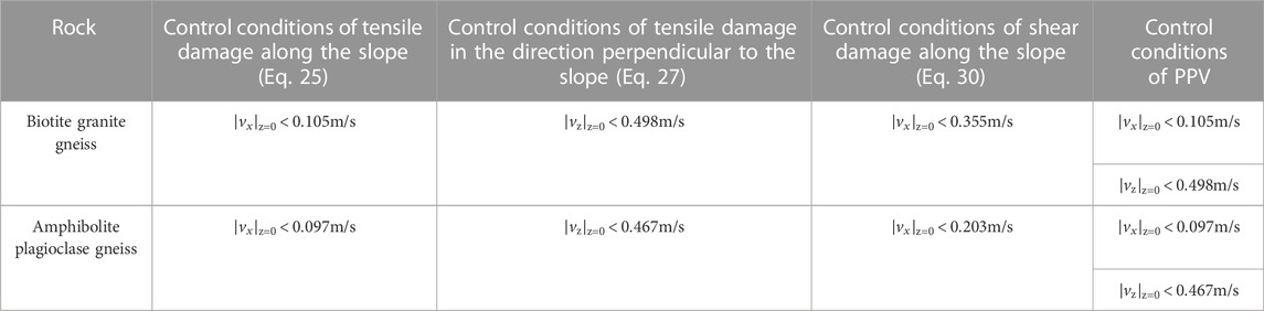
TABLE 6. Calculation results of vibration speed control value.
During the excavation of abutment slope, 74 blasting tests were carried out (Liu et al., 2007). The blasting vibration velocity (PPV) is monitored, and the acoustic velocity and macroscopic failure of the surface rock mass before and after blasting was compared. The test results showed that the main frequency of blasting vibration was in the range of 10Hz–50 Hz. During the 36 blasting tests above EL. 1315 m, the particle vibration velocity PPV at the measured point was within .10 m/s, the width of the rock fracture did not change significantly, and the slope did not collapse. The results of acoustic wave test showed that the thickness of the rock mass outside the blasting area where the wave velocity is significantly reduced after blasting was generally .6 m–1.0 m, which was considered as the vibration damage zone. During the 38 blasting tests under EL.1315 m, the maximum particle velocity at the measuring point was greater than 0.1 m/s, the thickness of the rock damage zone of the slope reached 0.8 m–1.2 m, and there was a phenomenon of local shallow rock collapse. When the vibration velocity of berm was .1–.15 m/s, there was no obvious change in the rock mass in the observation zone. When the vibration velocity of berm was .15–0.2 m/s, a small amount of rock mass fell off and a small amount of crack was widened. When the vibration velocity of the berm exceeded .25 m/s, a large number of rock masses fell off and cracks were obviously widened. Therefore, when the rock mass damage control was taken as the target, the vibration velocities obtained from Eqs 25, 27 and 30 were in good agreement with the experimental results.
However, it is difficult to estimate the mechanical parameters of rock mass accurately, and those parameters have strong discreteness. Therefore, it is necessary to determine the reasonable blasting vibration velocity according to the characteristics of rock mass and slope in different areas and the engineering experience.
6 Conclusion
Based on Rayleigh wave propagation theory, a theoretical method for determining the velocity of blasting vibration to control the damage of rock slopes is proposed. The following conclusions can be drawn from this research.
1) The peak allowable surface vibration velocity that guarantees no damage occurs in simple slope rock mass can be obtained with considering the tensile and shear failure modes of the rock mass.
2) The theoretical model gives a sufficiently good match against the numerical results and can therefore be used in practical engineering.
3) The allowable vibration velocity of the arch dam slope of Xiaowan Hydropower Station is calculated by the proposed method. The calculated results are in good agreement with the actual rock mass damage.
4) The method is not suitable for the prediction of allowable vibration velocity of rock mass near the blast hole, nor for the slope rock mass with the controlled weak structural plane. It should be noted that the mechanical parameters of rock mass are difficult to be accurately estimated, and the allowable blasting vibration velocity should be determined comprehensively according to the damage control of rock mass and the overall stability of slope.
Data availability statement
The original contributions presented in the study are included in the article/Supplementary Material, further inquiries can be directed to the corresponding author.
Author contributions
Coneptualization, JS and YJ; methodology, JS and YY; formal analysis and investigation: JS, YJ, ZZ, and YY; draft preparation: JS and ZZ.
Acknowledgments
A grateful acknowledgement is given to the National Key R&D Program of China (2021YFC3100804), National Natural Science Foundation of China (42102329), Hubei Provincial Natural Science Foundation (2020CFA043 and 2021CFB541), Key Research and Development Project of Hubei Province (2020BCA084 and 2021BAD004).
Conflict of interest
The authors declare that the research was conducted in the absence of any commercial or financial relationships that could be construed as a potential conflict of interest.
Publisher’s note
All claims expressed in this article are solely those of the authors and do not necessarily represent those of their affiliated organizations, or those of the publisher, the editors and the reviewers. Any product that may be evaluated in this article, or claim that may be made by its manufacturer, is not guaranteed or endorsed by the publisher.
References
Chen, M., Lu, W. B., and Shu, D. Q. (2009). Calculation method of equivalent acceleration for limit equilibrium analysis of slope under blasting vibration. Chin. J. Rock Mech. Eng. 28 (4), 784–790.
Chinese National Standard, (2015). Safety regulations for blasting. Beijing, China: State Standardization Publishing House.
Earth Production China Limited (2020). Civil engineering testing instruments. http://www.epl.com.cn/pagelist/view.php?aid=9270.
Jiang, Y., Xu, W., Wang, R., Wang, R., and Zhang, Z. (2010). Experimental study of rheological mechanical properties of arch dam abutment rock and its long-term stability analysis. Chin. J. Rock Mech. Eng. 29 (S2), 3699–3709.
Liu, M. S., Wu, C. Q., and Zhang, Z. Y. (2007). Experimentation on judging standard of blasting vibration safety in high slope excavation of Xiaowan hydropower station. J. Yangtze River Sci. Res. Inst. 24 (1), 40–43.
Lu, W., Luo, Y., Chen, M., and Shu, D. Q. (2012). An introduction to Chinese safety regulations for blasting vibration. Environ. Earth Sci. 67, 1951–1959. doi:10.1007/s12665-012-1636-9
Luo, Y., Lu, W. B., Chen, M., and Shu, D. Q. (2010). View of research on safety criterion of blasting vibration. Blasting 27 (1), 14–22.
Quagliata, A., Ahearn, M., Boeker, E., Roof, C., Meister, L., and Singleton, H. (2018). “Transit noise and vibration impact assessment manual, FTA Report No. 0123 (Cambridge, MA, USA: Volpe National Transportation Systems Center).
Rosenthal, Michael F., and Morlock, Gregory L. (1987). Blasting guidance manual. Office of surface mining reclamation and enforcement. Washington, DC, USA: US Department of the Interior.
Savely, J. P. (1986). Preprints for presentation at the SME annual meeting. New Orleans: Society of Mining Engineers of AIME.Designing a final wall blast to improve stability
Skipp, B. O. (1998). Ground dynamics and man-made processes: Prediction, design and management. Overdale, TF, UK: Thomas Telford.
United States. Bureau of Mines, , and Siskind, D. E. (1980). Structure response and damage produced by ground vibration from surface mine blasting. New York, NY, USA: US Department of the Interior, Bureau of Mines.
Keywords: slope, blasting, Rayleigh wave, dynamic stress, damage, vibration limit
Citation: Sun J, Jia Y, Zhang Z and Yao Y (2023) Study on blast-induced ground vibration velocity limits for slope rock masses. Front. Earth Sci. 10:1098630. doi: 10.3389/feart.2022.1098630
Received: 15 November 2022; Accepted: 28 December 2022;
Published: 11 January 2023.
Edited by:
Tianshou Ma, Southwest Petroleum University, ChinaReviewed by:
Honglue Qu, Southwest Petroleum University, ChinaPing Wang, Lanzhou Earthquake Research Institute, China Earthquake Administration, China
Copyright © 2023 Sun, Jia, Zhang and Yao. This is an open-access article distributed under the terms of the Creative Commons Attribution License (CC BY). The use, distribution or reproduction in other forums is permitted, provided the original author(s) and the copyright owner(s) are credited and that the original publication in this journal is cited, in accordance with accepted academic practice. No use, distribution or reproduction is permitted which does not comply with these terms.
*Correspondence: Jinshan Sun, c3Vuamluc2hhbkBqaHVuLmVkdS5jbg==