 J. W. Shi1,2
 P. Y. Zhou
 S. Y. Fan
- 1Shaanxi Key Laboratory of Geotechnical and Underground Space Engineering, Xi’an University of Architecture and Technology, Xi’an, China
- 2Gongke Industrial Group Co. Ltd., Xi’an, China
- 3School of Civil Engineering, Xi’an University of Architecture and Technology, Xi’an, China
- 4CCCC Bui lding Group Co. Ltd., Beijing, China
- 5China Road and Bridge Engineering Co. Ltd., Beijing, China
- 6School of Civil Engineering, Yancheng Institute of Technology, Yancheng, China
Underground engineering construction is facing increasingly complex geological conditions and engineering challenges, such as surrounding rock deformation and lining cracking, that seriously threaten the safety of tunnel construction and operation. Aiming at these problems, a pipeline tunnel crossing jointed expansive mudstone strata was taken as an example, and the disaster characteristics of surrounding rock and lining were analyzed through field investigation. The disaster-causing mechanism and corresponding control measures were studied through laboratory tests and numerical simulations, which were then applied to actual construction. Meanwhile, the deformation and stress response of the surrounding rock and tunnel structure were analyzed and investigated through monitoring and numerical data. The results showed that the vault settlement and horizontal convergence deformation of surrounding rock were reduced by 64.69 mm and 54.74 mm, respectively, under the improved construction scheme. The maximum surrounding rock stress was 430.26 kPa under the improved construction scheme, which was 18.15% lower than the original stress. The maximum axial force of the steel arch frame was 33.02 kN, ensuring the stability of the supporting structure and tunnel construction safety. Finally, the rationality and effectiveness of the reinforcement measures adopted were assessed.
1 Introduction
With the rapid development of infrastructure, tunnels and underground structures construction are facing more complex geological and construction problems, such as surrounding rock large deformation, seepage and mud bursts, high geostress, and adjacent construction (Lin et al., 2019; Fan et al., 2021; Fan et al., 2022; Tian et al., 2021; Tian et al., 2022; Guo et al., 2022; Zhou et al., 2022; Zhu et al., 2022; Liu et al., 2023). More and more tunnels are facing the problems of large buried depth and surrounding rock deformation and cracking, especially in areas with developed joint structures that are under the action of geological eccentric compression (Cao et al., 2018; Winn et al., 2019; Feng et al., 2021; Zhang et al., 2022a; Zhang et al., 2022b; Wang et al., 2022). Selen et al. (2020) performed extensive testing to determine the slaking and disintegration behavior of these rocks and assessed the mineralogical composition of flysch and serpentinite from the headrace tunnel of the Moglice Hydropower Project in Albania. The clay minerals in swelling rocks will cause volume expansion and disintegration of rocks after water softening. That study is a good reference for the cognition and control of the mechanical properties of expansive rock materials. Tai et al. (2020) examined the electromechanical chamber in the Tashan Coal Mine, adopting numerical simulation to analyze the surrounding rock deformation and failure characteristics during the tunneling process. Through analyzing the deformation and failure, Tai et al. (2020) suggested grouting integrated with high-strength bolts and anchor cables as a supporting measure that could effectively control the deformation. Liu et al. (2021) carried out a swelling test, scanning electron microscope tests, and a laboratory loading test on the swelling mudstone to further study the water effect on the swelling and mechanical properties of swelling mudstone samples. It was found that the internal friction angle did not change with the water content, while the cohesion decreased with the increasing water content. That study explained the reasons for the decrease in cohesive force of expansive mudstone and provided a strong explanation for the weakening mechanism about its mechanical properties. Luo et al. (2022) performed a series of true triaxial tests to investigate the influence of water on stress-induced failure in D-shaped hard rock tunnels. Softened by water, the energy storage capacity of surrounding rock decreases, the dissipation energy increases during deformation and failure, and the spalling failure of rock is induced by stress. That study has guiding significance for the understanding of rock failure mechanism under water–rock weakening and the formulation of corresponding control measures.
The construction methods are of great significance to surrounding rock stability and construction safety. In particular, timely and reasonable supporting structures should be constructed after tunneling in the soft stratum to avoid surrounding rock deformation and structural damage (Mikaeil et al., 2019; Li et al., 2020; Leng et al., 2021; Li et al., 2021; Pandit and Babu 2021; Liu et al., 2022a; Zhang et al., 2022c; Zhang et al., 2022d; Guan et al., 2022). Rooh et al. (2018) established a comprehensive simulation program to study the relationship between rock mass quality and longitudinal displacement profile (LDP). They analyzed the results of the numerical modelling and showed that the LDP curves of surrounding rock with high quality (GSI > 60) matched well. Based on intact rock strength, joint shear strength, and joint persistence, Renani et al. (2019) developed linear and non-linear failure criteria utilizing an analytical model of rock mass with non-persistent joints. The model was verified through comprehensive tests on undisturbed Panguna andesite and thermally granulated Carrara marble with natural joints. Reasonable excavation and support can ensure the safety and progress of tunnel construction. Feng et al. (2019) studied the deformation of surrounding rock and strata of large-section tunnels under different supporting and continuous blasting schemes. Results showed that the installation of initial ground support after two rounds of blasting produced the most regular and minimum tunnel internal forces, and this installation sequence significantly accelerated tunnel construction. The conclusions of that study are of great significance to ensure the safe and rapid construction of a tunnel and to reduce the time and economic cost of tunnel construction.
As an economical and effective active support method, bolt support has been widely used in engineering support for tunnels and underground mining. Liu et al. (2020a) independently developed an anchoring synergistic component (ASC) and mainly investigated the optimization of the bolt anchoring structure and the enhancement of the bolts’ ability to control the surrounding rock deformation by combining the numerical simulation and laboratory testing. The result indicated that the anchoring force and bearing capacity of the anchoring structure were noticeably improved with the ASC installed between the resin cartridges. Qin et al. (2022) analyzed the evolution of different failure modes using a shallow tunneling method in a loose granular stratum through DEM calculation, and the prevention mechanism was discussed. Comprehensive construction measures were suggested from the aspects of pre-support, excavation, bolt driving, and collapse prevention that could provide valuable references for tunnel construction control in similar projects. The aforementioned studies have laid the foundation for studying the soft rock deformation, and the deformation of surrounding rock and lining cracking in soft rock strata needs further study.
The adverse effect of broken soft rock on the stress and deformation of tunnel structure and the effective control measures were studied in this paper based on the tunnel of a natural gas pipeline crossing soft rock strata. This study first analyzed the disaster characteristics of surrounding rock deformation and lining cracking. Then, the corresponding control measures were proposed and applied to actual construction. The deformation and stress evolution law of surrounding rock and supporting structure after adopting the improved construction scheme were analyzed based on the field monitoring data to ensure the stability of supporting structure and construction safety. Finally, combined with the measured data and numerical simulation, the rationality and effectiveness of the reinforcement measures adopted were assessed through comparative analysis of the deformation and stress response characteristics of the surrounding rock and supporting structure. The research conclusions provide theoretical guidance for design and construction.
2 Engineering situations and geological conditions
The natural gas pipeline starts in Turkmenistan, passes through Turkish-Ukish, Uzbekistan, Tajikistan, and Kyrgyzstan from west to east, and ends in Kashgar, China. The general situation of the background project is shown in Figure 1A. The tunnel is 1860 m in length with a maximum buried depth of 163 m, and the width × height of the tunnel section is 4.5 m × 4.5 m.
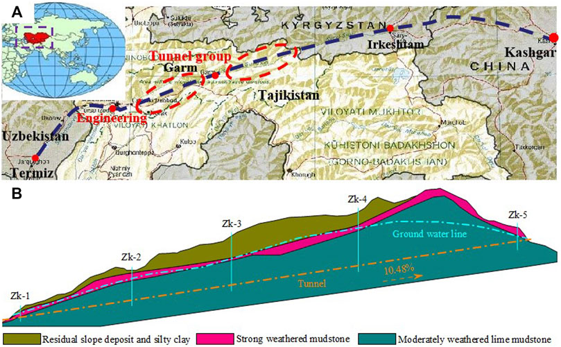
FIGURE 1. (A) Project situation and (B) geological profile.
The overlying soil layer of the tunnel area was mainly quaternary residual slope soil and silty clay with a thickness of 1–20 m. The lower soil was mainly weathered mudstone (Pg1 + 2), with a developed layered joint structure and poor stability. The tunnel entrance is located at the slope foot, and the slope was gradual with loess-type silty clay. The exit was located at the mountainside slope, and the slope soil was mainly silty clay with a small amount of gravel. The groundwater in the tunnel site area mainly includes pore water and bedrock fissure water, which was mainly replenished by precipitation and ice meltwater. In addition, the groundwater had weak corrosion on the concrete structures and steel bars. The geological profile is shown in Figure 1B, and the geotechnical parameters are shown in Table 1.
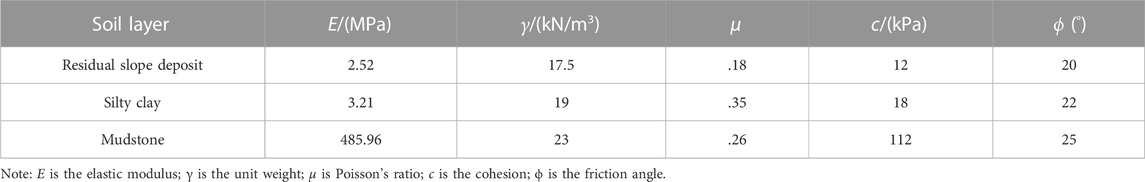
TABLE 1. Geotechnical parameters.
3 Disaster characteristics and cause analysis
3.1 Cracking condition on site
During K1 + 663 ∼ K1 + 683, longitudinal cracks with a length of roughly 1.5 m and a width of 2–4 mm appeared on primary supports at the right hance, accompanied by concrete scaling. During K1 + 690 ∼ K1 + 700, longitudinal and transverse cracks with a width of 1–3 mm appeared on the secondary lining at the left side wall, accompanied by local shedding and water seepage. Affected by geological eccentric compression, some deeper cracks appeared on the vault, with a width of more than 2 mm. The field cracking situation is shown in Figure 2.
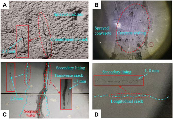
FIGURE 2. Cracking on-site of (A,B) primary supports and (C,D) secondary lining.
3.2 Disaster cause analysis
3.2.1 Layered joint structure
Combined with geological survey data, it is known that the tunnel site’s surrounding structure had developed layers. The developed layered structure will intensify the inhomogeneity of the surrounding rock stress on both sides, resulting in the asymmetric distribution of deformation and cracking on both sides. In addition, the layered structure of the surrounding rock had a sliding and separating trend along the joint surface under the force of high geostress, which aggravated the risk of surrounding rock deformation and lining cracking (Liu et al., 2020b; Zhang et al., 2022e; Li et al., 2022).
3.2.2 Swelling property of mudstone
The groundwater runoff modulus was 2.28–7.32 L/skm2 in the dry season and 4.85–9.58 L/skm2 in the rainy season. The field investigation showed that the layered structure and fissures in the tunnel site were relatively developed, which facilitated the seepage of groundwater. The water–rock physicochemical reaction intensified, resulting in the strength degradation of the surrounding rock (Yang et al., 2022) and inducing uncoordinated surrounding rock deformation and cracking of the lining. Three cores were drilled in the collapsed tunnel section for laboratory tests to obtain the mineral composition and expansion (Ahn et al., 2021; Wang et al., 2022). The results are shown in Table 2.
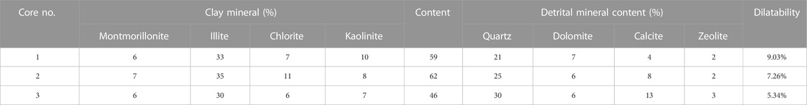
TABLE 2. Test results of mudstone composition and dilatability.
Table 2 shows that the mineral composition of mudstone was similar in each core. The clay minerals were mainly illite, followed by kaolinite, chlorite, and montmorillonite, which can easily cause mudstone expansion. The laboratory test results showed that the expansion rates of the three cores were 9.03%, 7.26%, and 5.34%, respectively, which was not conducive to surrounding rock stability. Moreover, the groundwater could aggravate the dilatability and strength damage of the mudstone, threatening tunnel safety and the stability of the surrounding rock.
3.2.3 High geostress
Surrounding rock strength is an important design parameter in tunnel engineering that directly affects the load borne by the supporting structure and the overall stability of the tunnel. The maximum buried depth of the No. 1 tunnel was 260 m, and the surrounding rock comprised grade V and VI weathered mudstone. Based on laboratory tests and field surveys, the uniaxial saturated compressive strength of the surrounding rock was 11.8–24.2 MPa, and the maximum horizontal principal stress and vertical stress were about 2.8–3.6 MPa and 4.2–5.1 MPa, respectively. The strength–stress ratio was 4.2–5.7; therefore, the surrounding rock stress was not uniform, and some areas were affected by high geostress (Yang et al., 2017; Liu et al., 2022b; Xu et al., 2022).
3.2.4 Unqualified supporting structure and lining
It was found that the steel arch frame spacing of the primary supports in the collapsed section of the tunnel was too large, resulting in uneven stiffness and deformation along the tunnel. In addition, the concrete thickness in the disaster range was about .06 m thinner than the design value, leading to insufficient strength, uneven stress, and cracking of the lining structure.
4 Improved measures and engineering application
4.1 Solution measures
Combined with the disaster-causing mechanism analysis of the layered jointed mudstone stratum in background engineering, the following targeted control measures were proposed: (a) according to the existing engineering experience (Huang et al., 2021; Liu et al., 2022c), the two-step excavation method with the excavation footage F=1.2 m was used. (b) Pre-support measures of grouting pipe sheds were adopted. (c) The steel arch frame was densely arranged, and the locking bolt and longitudinal connection reinforcement were added to improve the overall stiffness of the supporting structure. (d) To improve the integrity of the surrounding rock, grouting bolts were used and arranged vertically to the layered joint surface instead of the original. (e) The surrounding rock was grouted by controlling the grouting pressure of 2 MPa to enhance the bonding between the joint surface and the integral rock mass. (f) Waterproof material was laid down before pouring the secondary lining concrete to prevent pore water from penetrating into the secondary lining structure. At the same time, the secondary lining concrete should be poured in strict accordance with the design, and subsequent maintenance should be carried out well. The implementation of improved control measures during actual construction is shown in Figure 3.
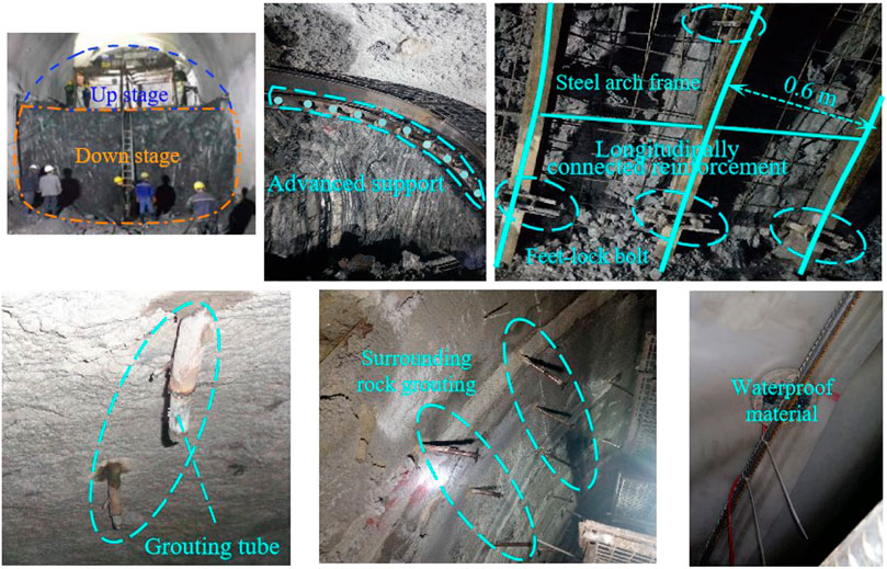
FIGURE 3. Field application of improved construction measures.
4.2 Engineering application and measured data analysis
The control measures proposed were applied during the subsequent tunnel construction. The earth pressure sensor and displacement meter were embedded to monitor the stress and deformation of the surrounding rock. Meanwhile, the rebar stress meter was welded onto the steel arch web to test the force of the steel arch frame. The layout of monitoring points and measuring component installation on-site is shown in Figure 4. The stress and deformation of the surrounding rock and supporting structure were monitored strictly during construction. When surrounding rock deformation or supporting structure stresses were too large, the construction was suspended, and the reasons were analyzed to ensure construction safety.
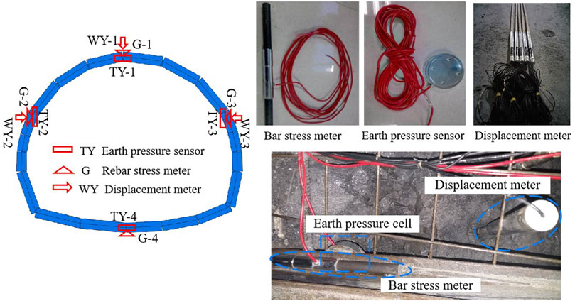
FIGURE 4. Layout of measuring points and installation of measuring components.
4.3 Analysis of measured results
4.3.1 Deformation of surrounding rock
Figure 5 shows the cumulative deformation and deformation rate of the surrounding rock.
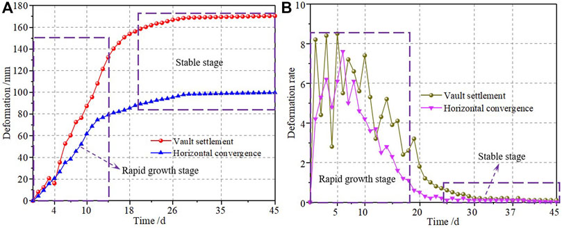
FIGURE 5. Result of surrounding rock deformation: (A) cumulative deformation curve and (B) deformation rate curve.
Figure 5 shows that surrounding rock deformation mainly occurred in the early stage; the amount of vault settlement and horizontal convergence in the first 10 days accounted for 44.86% and 52.29% of the total deformation, respectively. The deformation rate decreased after primary supporting construction, while the cumulative deformation continued to increase. The cumulative settlement and convergence deformation increased by 43 mm and 20.6 mm, respectively, during the 11–20-day period after inverted arch construction and forming a closed ring with primary supports, which enhanced the stability of the supporting structure and controlled the surrounding rock deformation. Finally, the vault settlement and horizontal convergence stabilized at 170.52 and 99.81 mm, respectively. Meanwhile, there was no cracking on the primary supports and secondary lining during subsequent construction, indicating that the improved measures worked well. Comparing the settlement and convergence values revealed that the overall deformation of the surrounding rock was dominated by settlement. However, the horizontal convergence was also large, so the surrounding rock deformation should be strictly monitored to ensure construction safety.
4.3.2 Stress of surrounding rock
Data from the earth pressure sensor were analyzed to obtain the stress variation of the surrounding rock, as shown in Figure 6.
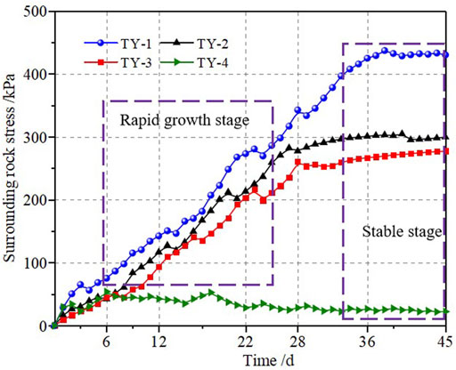
FIGURE 6. Stress of surrounding rock.
Figure 6 shows that the stress was distributed unevenly and increased in fluctuation during construction. In the first 6 days, the surrounding rock stress at measuring points #1–4 reached 75.48, 38.45, 45.35, and 54.05 kPa, respectively. The surrounding rock stress at the vault and hance continued to increase, while the value at the arch bottom changed slightly. After 28 days, the stress at the vault and two hances reached 79.69%, 92.56%, and 94.13% of the total stress, respectively. After inverted arch construction and forming a closed ring with initial support, the surrounding rock stress at the hance and arch bottom gradually stabilized, while the value of the vault increased continuously. After 40 days, the stress at the vault gradually stabilized with the highest value of 430.26 kPa. Affected by geological eccentric compression, the stress at the two hances was larger, reaching 292.36 and 275.29 kPa, respectively. The stress at the arch bottom was small and remained stable, ensuring safe tunnel construction.
4.3.3 Force of steel arch frame
The axial force variation of the steel arch frame is shown in Figure 7.
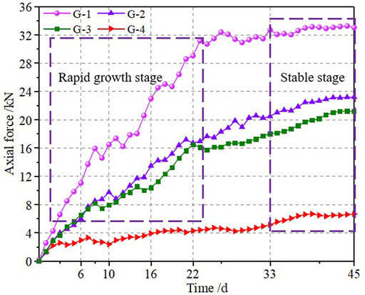
FIGURE 7. Axial force of the steel arch frame.
Figure 7 shows that the force variation of the steel arch frame was similar to surrounding rock stress, and the force increased rapidly in the early stage of construction, indicating that the steel arch frame bore loading immediately and restricted the surrounding rock deformation. In the first 8 days, the axial forces of the steel arch frame at measuring points #1–4 were 15.91, 7.37, 8.18, and 2.71 kN, respectively. The force value at the vault and hance increased with continuous excavation, while the value at the arch bottom remained stable. After 28 days, the axial forces at the vault and two hances reached 95.03%, 85.61%, and 78.97% of the largest value, respectively. After inverted arch construction and forming a closed ring with primary supports, the axial force of the steel arch frame gradually stabilized. Finally, the axial forces at measuring points #1–4 were 33.02, 20.15, 21.16, and 6.62 kN, respectively, ensuring construction safety.
5 Analysis and discussion
Aiming at the problems of background engineering and the disaster-causing mechanism analysis mentioned in the previous content, this study analyzed the deformation and stress characteristics of surrounding rock with a developed layered structure and supporting structure. The effectiveness of the improved measures proposed in this study was evaluated by comparing results under the original and improved construction scheme.
5.1 Model and parameters
The deformation and stress of the surrounding rock and supporting structure before and after reinforcement treatment were simulated and analyzed using Midas GTS/NX, numerical calculation software designed for geotechnical engineering (Komu et al., 2020). The model fully considers the influence range of construction disturbance to ensure the reliability and effectiveness of calculation results. According to the “Code for design of gas transmission pipeline engineering,” considering the maximum construction disturbance range required a model of size 60 m × 100 m × 80 m (length × width × height), as shown in Figure 8. The upper surface of the model was a free surface. The horizontal displacement was constrained on the surrounding boundary, and the horizontal and vertical displacements were constrained on the bottom boundary.
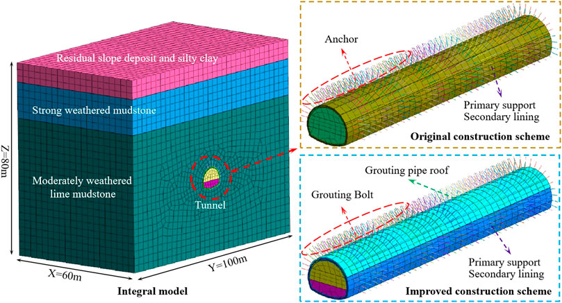
FIGURE 8. Three-dimensional finite element model.
The geotechnical parameters were obtained from the geological exploration report and laboratory test data (see Table 1), and the reinforcement materials parameters are shown in Table 3.
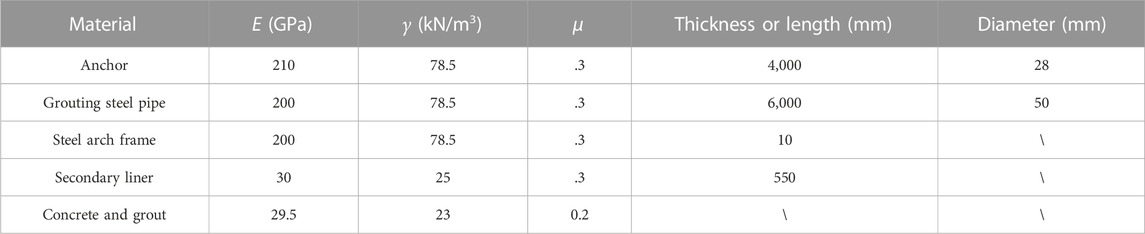
TABLE 3. Material parameters of the supporting structure.
5.2 Result analysis
5.2.1 Plastic zone
According to the Mohr–Coulomb yield criterion, when the shear stress reaches the shear strength of the rock mass, the rock mass will enter the plastic stage. Thus, the plastic zone was the area where the shear stress exceeded the rock shear strength. The development process of plastic zones with construction steps (S) increasing under two construction schemes is shown in Figure 9.
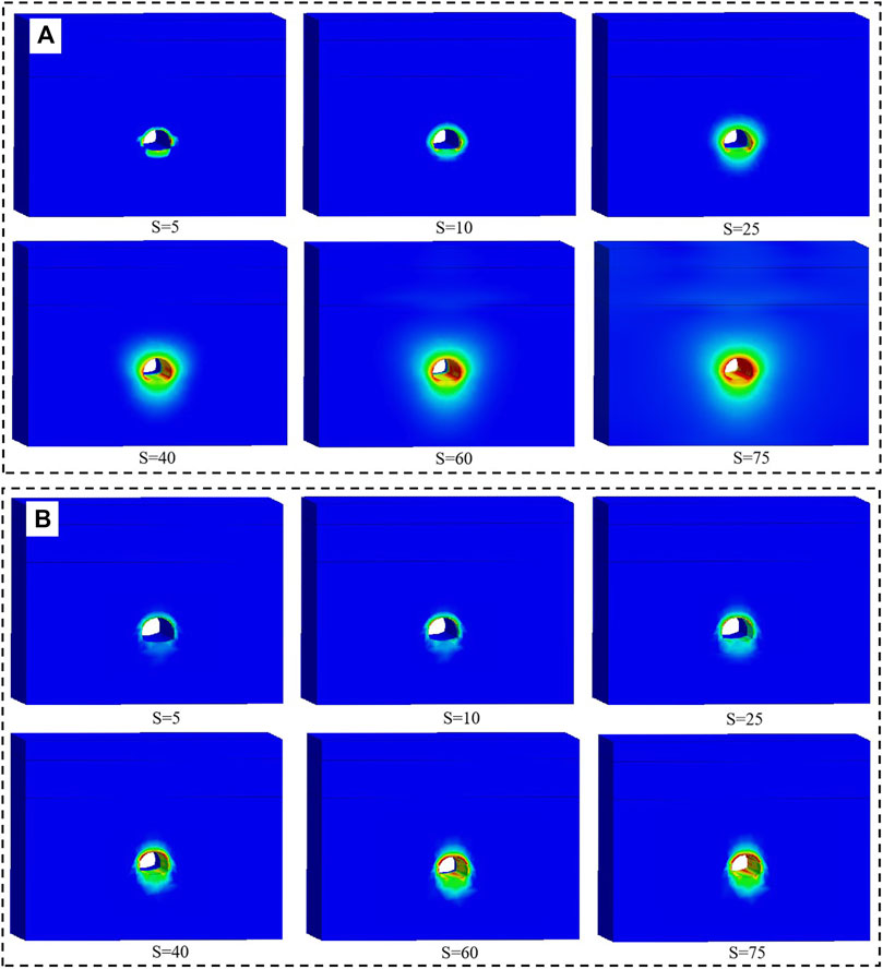
FIGURE 9. Development process of plastic zones under two construction schemes: (A) original construction scheme and (B) improved construction scheme.
Figure 9 shows that the plastic zone under two construction schemes expanded with tunnel excavation. The plastic zone of the surrounding rock developed rapidly, and the response range was large under the original construction scheme. The plastic zone showed an asymmetric development trend in the early stage, which increased sharply later. In particular, the plastic response characteristic of the surrounding rock became more obvious closer to the cave wall, which contributed to the large deformation of the surrounding rock and the actual disaster. Under the improved construction scheme, the integrity of the surrounding rock was improved by using grouting bolts and surrounding rock grouting measures, and the development of the surrounding rock plastic zone was controlled well. In addition, the plastic deformation response of the side wall under the original construction scheme was obvious when S = 40. Under the improved scheme, the plastic deformation response of the vault area was larger, indicating that the advanced support measures had played a role and effectively bore the load of the surrounding rock. After tunnel excavation, the plastic zone range was reduced, and the distribution was more uniform, indicating that the construction measures adopted can effectively improve the stress state of the surrounding rock and ensure the stability of the surrounding rock.
5.2.2 Deformation of surrounding rock
The variation of surrounding rock deformation at the measured section under two construction schemes is shown in Figure 10.
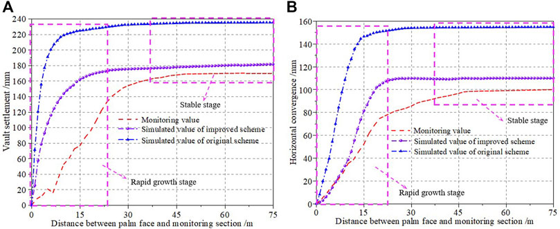
FIGURE 10. Variation of surrounding rock deformation: (A) vault settlement and (B) horizontal convergence.
Figure 10 shows that the simulated development process results were similar to the measured results, and the vault settlement and horizontal convergence deformation increased rapidly early. When the palm surface pulled 30 m ahead of the monitoring section, the surrounding rock deformation slowed and gradually became stable. The simulation values of vault settlement under the two construction schemes were 235.21 and 181.45 mm, respectively, and the horizontal convergence values were 154.55 and 109.85 mm, respectively. Two deformations under the improved construction scheme were reduced by 34.29% and 39.46% compared to the original construction scheme, indicating that the improvement measures can effectively control the deformation of surrounding rock and ensure construction safety. Moreover, the measured values were closer to the simulation values under the improved construction scheme, and the differences between the two deformations were 9.45 and 10.59 mm, respectively. Considering the difference between the actual construction and numerical simulation, it is necessary to strictly monitor the deformation of surrounding rock during the actual construction process.
5.2.3 Stress of surrounding rock
The variation of maximum surrounding rock stress at the measured section under two construction schemes is shown in Figure 11.
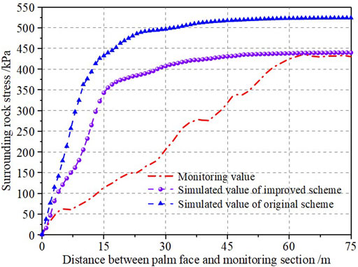
FIGURE 11. Variation of surrounding rock stress.
Figure 11 shows that the surrounding rock stress increased sharply in the early stage of excavation. When the palm surface was pushed 15 m ahead of the monitoring section, the maximum stress under the two construction schemes accounted for 81.29% and 73.26% of the cumulative value, respectively. Compared with the simulation value, the measured stress of the surrounding rock increased slowly, accounting for 26.82% of the cumulative value. During the subsequent construction process, the simulated value gradually stabilized. The measured results showed that the surrounding rock stress was gradually released, which was conducive to surrounding rock stability. Finally, the measured results were closer to the simulation results of the improved construction scheme, with a difference of 9.86 kPa. Both sets of results met the requirements of surrounding rock stability, indicating that adopting the improved measures can effectively ensure construction safety.
Deformations and internal force of primary supporting: The deformations and internal forces of the primary supports at the measured section under two construction schemes are shown in Figure 12.
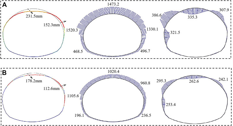
FIGURE 12. Deformation and internal force of primary supports: (A) original construction scheme and (B) improved construction scheme.
Figure 12 shows that the deformation trend and internal force distribution of the primary supports under the two construction schemes were similar. After tunneling excavation, the left spandrel and vault were squeezed into the tunnel, and the right side wall tended to be squeezed out of the tunnel. The vertical deformation and horizontal deformation of the primary supports were reduced by 53.3 and 39.7 mm, respectively, under the improved construction scheme. It indicated that adopting the improved measures according to the previous mechanism analysis can effectively control the deformation of the surrounding rock and the supporting structure, which is beneficial to tunnel stability. In addition, the maximum internal force was reduced, and the distribution was more uniform after improving construction. Compared with the original construction scheme, the maximum axial force and bending moment were reduced by 414.7 kN and 91.3 kN m, respectively. These results show that the measures to enhance the stiffness and integrity of the primary supports can effectively improve the overall bearing capacity of the supporting structure, which is beneficial to construction safety.
6 Conclusion
The disaster-causing mechanism of surrounding rock deformation and secondary lining cracking of the construction of the No. 1 tunnel of the China–Tajikistan natural gas pipeline was studied. The effectiveness of the reinforcement measures was evaluated. Through analysis and discussion, the following conclusions can be drawn.
1) Combined with the analysis of the disaster-causing mechanism, it was found that the developed layered structure, high geostress, and the expansibility of mudstone will cause large deformation of the surrounding rock and lining cracking. The slip deformation of the layered rock mass along the structural plane was the particular reason for uneven tunnel deformation.
2) The deformation and stress of the tunnel structure were controlled and gradually stabilized after the integrity and stiffness of the rock mass and supporting structure were enhanced. The maximum values of vault settlement and horizontal convergence were 170.52 and 99.81 mm, respectively. The maximum stress of the surrounding rock and steel arch frame occurred at the vault, reached 430.26 kPa and 33.02 kN, and ensured construction safety and the stability of the surrounding rock.
3) The deformation of the surrounding rock and primary supporting were well controlled under comprehensive control measures. The vault settlement and horizontal convergence of the primary supports were reduced by 23.02% and 26.07%, respectively, compared to the original construction scheme. Moreover, the measured results of surrounding rock deformation were only 3.5% higher than the simulated values of the improved scheme, verifying the feasibility of the improvement measures.
4) The force distribution of the primary supports was improved, and the maximum axial force and bending moment were reduced by 27.28% and 23.62%, respectively, under the improved construction scheme. Meanwhile, the tensile region was transformed into a compressive state, giving full play to the bearing role of the supporting structure and ensuring the stability and safety of the tunnel structure.
Data availability statement
The original contributions presented in the study are included in the article/Supplementary Material; further inquiries can be directed to the corresponding author.
Author contributions
JS conceived and designed the methods, provided a guide to the monitoring and theoretical research for the study, and economically supported the project. PZ, XL, and SF completed the numerical model, data analysis, and writing of the manuscript. ZZ, BZ, and YC provided the monitoring materials and completed the data collection.
Funding
The authors are grateful for the support of the National Natural Science Foundation of China (No. 51578447), the Science and Technology Innovation Team of Shaanxi Innovation Capability Support Plan (No. 2020TD005), the Science and Technology Development Program of Shaanxi Provincial Department of Housing and Urban-Rural Construction (No. 2019-K39), and the Special Project of Shaanxi Provincial Education Department (No. 20JK0709). The financial supports are gratefully acknowledged, and the data are available for the journal.
Conflict of interest
JS was employed by Gongke Industrial Group Co. Ltd. ZZ was employed by CCCC Building Group Co. Ltd. BZ was employed by China Road and Bridge Engineering Co. Ltd.
The remaining authors declare that the research was conducted in the absence of any commercial or financial relationships that could be construed as a potential conflict of interest.
Publisher’s note
All claims expressed in this article are solely those of the authors and do not necessarily represent those of their affiliated organizations, or those of the publisher, the editors, and the reviewers. Any product that may be evaluated in this article, or claim that may be made by its manufacturer, is not guaranteed or endorsed by the publisher.
References
Ahn, H. S., Lim, J., and Kim, S. W. (2021). Magnetic properties of a holocene sediment core from the yeongsan estuary, southwest korea: Implications for diagenetic effects and availability as paleoenvironmental proxies. Front. Earth Sc-switz. 9, 593332. doi:10.3389/feart.2021.593332
Cao, R. H., Cao, P., Lin, H., Ma, G. W., Zhang, C., and Jiang, C. (2018). Failure characteristics of jointed rock-like material containing multi-joints under a compressive-shear test: Experimental and numerical analyses. Arch. Civ. Mech. Eng. 18, 784–798. doi:10.1016/j.acme.2017.12.003
Fan, S. Y., Song, Z. P., Xu, T., Wang, K. M., and Zhang, Y. W. (2021). Tunnel deformation and stress response under the bilateral foundation pit construction-a case study. Arch. Civ. Mech. Eng. 21 (3), 109. doi:10.1007/s43452-021-00259-7
Fan, S. Y., Song, Z. P., Xu, T., and Zhang, Y. W. (2022). Investigation of the microstructure damage and mechanical properties evolution of limestone subjected to high-pressure water. Constr. Build. Mater 316, 125871. doi:10.1016/j.conbuildmat.2021.125871
Feng, F., Li, X. B., Luo, L., Zhao, X. D., Chen, S. J., Jiang, N., et al. (2021). Rockburst response in hard rock owing to excavation unloading of twin tunnels at great depth. B Eng. Geol. Environ. 80 (10), 7613–7631. doi:10.1007/s10064-021-02377-1
Feng, J. M., Yan, C. W., Ye, L., Ding, X. Q., Zhang, J. R., and Li, Z. L. (2019). Evaluation of installation timing of initial ground support for large-span tunnel in hard rock. Tuun Uudergr Sp. Tech. 93, 103087. doi:10.1016/j.tust.2019.103087
Guan, K., Zhang, Q. Y., Liu, H. L., and Zhu, W. C. (2022). A new numerical procedure for the excavation response in Mohr-Coulomb rock mass exhibiting strain-softening behavior. Front. Earth Sc-switz 10, 872792. doi:10.3389/feart.2022.872792
Guo, H. S., Tong, J. Q., Sun, Q. C., Yang, X., Luo, W. J., and Yu, Y. (2022). Determination method of excavation damage zone based on surrounding rock damage-fracture ratio in underground engineering. Front. Earth Sc-switz. 10, 836313. doi:10.3389/feart.2022.836313
Huang, X., Li, L. F., Zhang, C. F., Liu, B., Li, K. J., Shi, H. B., et al. (2021). Multi-step combined control technology for karst and fissure water inrush disaster during shield tunneling in spring areas. Front. Earth Sc-switz 9, 795457. doi:10.3389/feart.2021.795457
Komu, M. P., Guney, U., Kilickaya, T. E., and Gokceoglu, C. (2020). Using 3d numerical analysis for the assessment of tunnel-landslide relationship: Bahce-nurdag tunnel (south of Turkey). Geotech. Geol. Eng. 38 (4), 1237–1254. doi:10.1007/s10706-019-01084-9
Leng, X. L., Wang, C., Sheng, Q., Chen, J., and Li, H. L. (2021). An enhanced ubiquitous-joint model for a rock mass with conjugate joints and its application on excavation simulation of large underground caverns. Front. Earth Sc-switz. 9, 744900. doi:10.3389/feart.2021.744900
Li, G., Hu, Y., Tian, S. M., Weibin, M., and Huang, H. L. (2021). Analysis of deformation control mechanism of prestressed anchor on jointed soft rock in large cross-section tunnel. B Eng. Geol. Environ. 80 (12), 9089–9103. doi:10.1007/s10064-021-02470-5
Li, G., Ma, F. S., Guo, J., Zhao, H. J., and Liu, G. (2020). Study on deformation failure mechanism and support technology of deep soft rock roadway. Eng. Geol. 264, 105262. doi:10.1016/j.enggeo.2019.105262
Li, Z. C., Wang, S. R., Li, L. C., and Zhang, J. Y. (2022). Numerical Investigation on interference of multiple hydraulic fractures in layered formation. Front. Earth Sc-switz. 10, 865155. doi:10.3389/feart.2022.865155
Lin, X. T., Chen, R. P., Wu, H. N., and Cheng, H. Z. (2019). Deformation behaviors of existing tunnels caused by shield tunneling undercrossing with oblique angle. Tunn. Undergr. Sp. Tech. 89, 78–90. doi:10.1016/j.tust.2019.03.021
Liu, C. D., Cheng, Y., Jiao, Y. Y., Zhang, G. H., Zhang, W. S., Ou, G. Z., et al. (2021). Experimental study on the effect of water on mechanical properties of swelling mudstone. Eng. Geol. 295, 106448. doi:10.1016/j.enggeo.2021.106448
Liu, D. M., Zhao, Z., Jin, X. M., Yang, C., Chen, W., Cai, Y. D., et al. (2022b)., 2022. Hydrodynamic and 420 geostress controls on CBM enrichment in the anze block, Southern Qinshui basin, North China. Geofluids, 9199715. doi:10.1155/2022/9199715
Liu, N. F., Li, N., Li, G. F., Song, Z. P., and Wang, S. J. (2022a). Method for evaluating the equivalent thermal conductivity of a freezing rock mass containing systematic fractures. Rock Mech. Rock Eng. 55 (12), 7333–7355. doi:10.1007/s00603-022-03038-9
Liu, N. F., Li, N., Wang, S. J., Li, G. F., and Song, Z. P. (2023). A fully coupled thermo-hydro-mechanical model for fractured rock masses in cold regions. Cold Reg. Sci. Techno.l. 2022 (205), 103707. doi:10.1016/j.coldregions.2022.103707
Liu, N. F., Li, N., Xu, C. B., Li, G. F., Song, Z. P., and Yang, M. (2020a). Mechanism of secondary lining cracking and its simulation for the Dugongling tunnel. Rock Mech. Rock Eng. 53 (10), 4539–4558. doi:10.1007/s00603-020-02183-3
Liu, S. W., He, D. Y., and Fu, M. X. (2020b). Experimental investigation of surrounding-rock anchoring synergistic component for bolt support in tunnels. Tunn. Undergr. Sp. Tech. 104, 103531. doi:10.1016/j.tust.2020.103531
Liu, Y. X., Zhang, Y. Q., Su, P. D., Zhang, G. Z., Qiu, P., and Tang, L. (2022c). Risk prediction of rock bursts and large deformations in YL tunnel of the Chongqing-Kunming high-speed railway. Front. Earth Sc-switz. 10, 892606. doi:10.3389/feart.2022.892606
Luo, Y., Gong, F. Q., and Zhu, C. Q. (2022). Experimental investigation on stress-induced failure in D-shaped hard rock tunnel under water-bearing and true triaxial compression conditions. B Eng. Geol. Environ. 81 (2), 76. doi:10.1007/s10064-021-02564-0
Mikaeil, R., Haghshenas, S. S., and Sedaghati, Z. (2019). Geotechnical risk evaluation of tunneling projects using optimization techniques (case study: The second part of emamzade hashem tunnel). Nat. Hazards 97 (3), 1099–1113. doi:10.1007/s11069-019-03688-z
Pandit, B., and Babu, G. L. S. (2021). Probabilistic stability assessment of tunnel-support system considering spatial variability in weak rock mass. Comput. Geotech. 137, 104242. doi:10.1016/j.compgeo.2021.104242
Qin, Y. W., Lai, J. X., Yang, T., Zan, W. B., Feng, Z. H., Liu, T., et al. (2022). Failure analysis and countermeasures of a tunnel constructed in loose granular stratum by shallow tunnelling method. Eng. Fail Anal. 141, 106667. doi:10.1016/j.engfailanal.2022.106667
Renani, H. R., Martin, C. D., and Cai, M. (2019). An analytical model for strength of jointed rock masses. Tunn. Undergr. Sp. Tech. 94, 103159. doi:10.1016/j.tust.2019.103159
Rooh, A., Nejati, H. R., and Goshtasbi, K. (2018). A new formulation for calculation of longitudinal displacement profile (LDP) on the basis of rock mass quality. Geomech. Eng. 16 (5), 539–545. doi:10.12989/gae.2018.16.5.539
Selen, L., Panthi, K. K., and Vistnes, G. (2020). An analysis on the slaking and disintegration extent of weak rock mass of the water tunnels for hydropower project using modified slake durability test. B Eng. Geol. Environ. 79 (4), 1919–1937. doi:10.1007/s10064-019-01656-2
Tai, Y., Xia, H. C., and Kuang, T. J. (2020). Failure characteristics and control technology for large-section chamber in compound coal seams-a case study in Tashan coal mine. Energy Sci. Eng. 8 (4), 1353–1369. doi:10.1002/ese3.598
Tian, X. X., Song, Z. P., Wang, H. Z., Zhang, Y. W., and Wang, J. B. (2022). Evolution characteristics of the surrounding rock pressure and construction techniques: A case study from taoshuping tunnel. Tunn. Undergr. Sp. Tech. 125, 104522. doi:10.1016/j.tust.2022.104522
Tian, X. X., Song, Z. P., and Zhang, Y. W. (2021). Monitoring and reinforcement of landslide induced by tunnel excavation: A case study from xiamaixi tunnel. Tunn. Undergr. Sp. Tech. 110, 103796. doi:10.1016/j.tust.2020.103796
Wang, J. B., Zhou, P. Y., Song, Z. P., Li, S. H., and Zhang, Q. (2022). A new calculation method for tunneling-caused stratum settlement. KSCE J. Civ. Eng. 26 (6), 2624–2640. doi:10.1007/s12205-022-1258-z
Wang, Z. Y., Nie, X., Zhang, C., Wang, M. R., Zhao, J. W., and Jin, L. D. (2022). Lithology classification and porosity estimation of tight gas reservoirs with well logs based on an equivalent multi-component model. Front. Earth Sc-switz. 10, 850023. doi:10.3389/feart.2022.850023
Winn, K., Wong, L. N. Y., and Alejano, L. R. (2019). Multi-approach stability analyses of large caverns excavated in low-angled bedded sedimentary rock masses in Singapore. Eng. Geol. 259, 105164. doi:10.1016/j.enggeo.2019.105164
Xu, C., Xia, C. C., and Han, C. L. (2022). Elastoplastic solutions for deep tunnel excavation in weak rocks with high geostress considering different stress release measures. Int. J. Appl. Mech. Early access 14. doi:10.1142/S1758825122500776
Yang, J. P., Chen, W. Z., Zhao, W. S., Tan, X. J., Tian, H. M., Yang, D. S., et al. (2017). Geohazards of tunnel excavation in interbedded layers under high in situ stress. Eng. Geol. 230, 11–22. doi:10.1016/j.enggeo.2017.09.007
Yang, M., Liu, N. F., Li, N., Xu, C. B., Li, G. F., and Cao, M. M. (2022). Failure characteristics and treatment measures of tunnels in expansive rock stratum. Front. Earth Sc-switz. 9, 805378. doi:10.3389/feart.2021.805378
Zhang, L., Niu, F. J., Liu, M. H., Ju, X., Wang, Z. W., Wang, J. C., et al. (2022e). Fracture characteristics and anisotropic strength criterion of bedded sandstone. Front. Earth Sc-switz. 10, 879332. doi:10.3389/feart.2022.879332
Zhang, Y. J., Wang, J. Y., and Xia, H. S. (2022a). Mechanism and sensitivity analysis of collapse in large section mountain neighborhood tunnels. Front. Earth Sc-switz. 10, 904655. doi:10.3389/feart.2022.904655
Zhang, Y. W., Fan, S. Y., Yang, D. H., and Zhou, Fei (2022b). Investigation about variation law of frost heave force of seasonal cold region tunnels: A case study. Front. Earth Sc-switz. 9, 806843. doi:10.3389/feart.2021.806843
Zhang, Y. W., Song, Z. P., and Weng, X. L. (2022c). A constitutive model for loess considering the characteristics of structurality and anisotropy. Soil Mech. Found. Eng. 59 (1), 32–43. doi:10.1007/s11204-022-09781-z
Zhang, Z. Y., Zhao, C. Y., Peng, L., Zhang, X. H., and Lei, M. F. (2022d). Research on the stability of shallow-buried large cross-section tunnel by construction method conversion. Front. Earth Sc-switz. 10, 831169. doi:10.3389/feart.2022.831169
Zhou, P. Y., Wang, J. B., Song, Z. P., Cao, Z. L., and Pei, Z. M. (2022). Construction method optimization for transfer section between cross passage and main tunnel of metro station. Front. Earth Sc-switz. 10, 770888. doi:10.3389/feart.2022.770888
Keywords: tunnel, deformation, lining cracking, reinforcement, monitoring
Citation: Shi JW, Zhou PY, Li X, Fan SY, Zhou ZF, Zhi B and Cheng Y (2023) Study of the disaster-causing mechanism and reinforcement measures for soft rock deformation and lining cracking. Front. Earth Sci. 10:1096635. doi: 10.3389/feart.2022.1096635
Received: 12 November 2022; Accepted: 28 December 2022;
Published: 17 January 2023.
Edited by:
Liang Cui, Lakehead University, CanadaReviewed by:
Zhanguo Xiu, Northeastern University, ChinaFeili Wang, Qingdao University of Technology, China
Copyright © 2023 Shi, Zhou, Li, Fan, Zhou, Zhi and Cheng. This is an open-access article distributed under the terms of the Creative Commons Attribution License (CC BY). The use, distribution or reproduction in other forums is permitted, provided the original author(s) and the copyright owner(s) are credited and that the original publication in this journal is cited, in accordance with accepted academic practice. No use, distribution or reproduction is permitted which does not comply with these terms.
*Correspondence: S. Y. Fan, ZmFuc2hlbmd5dWFuODhAMTYzLmNvbQ==