 Zelin Niu
 Yaqiong Wang4,5*
 Shengyuan Fan
94% of researchers rate our articles as excellent or good
Learn more about the work of our research integrity team to safeguard the quality of each article we publish.
Find out more
ORIGINAL RESEARCH article
Front. Earth Sci., 09 January 2023
Sec. Environmental Informatics and Remote Sensing
Volume 10 - 2022 | https://doi.org/10.3389/feart.2022.1094325
This article is part of the Research TopicAdvances in Development and Utilization of Underground SpaceView all 17 articles
Affected by dip angle and thickness of strata and the tunneling method, soft rock tunnel has obvious characteristics of large deformation, long deformation time and difficult support. Based on a case study of Gelong the deformation and failure mechanism of surrounding rock, stress characteristics of supporting structural and control method of large section highway tunnel passing through strong-medium weathered carbonaceous slate stratum are studied. This paper proposed construction method based on strengthening the longitudinal stiffness of supporting structure and increasing the integrity of surrounding rock, The results showed that the deformation of surrounding rock and the stress of supporting structure increased rapidly in the early stage of construction. The cumulative deformation of vault settlement and horizontal convergence reached 116.9 mm and 97.9 mm, respectively, accounting for 73.53% and 76.62% of the total deformation. The proportion of surrounding rock pressure shared by the primary support and the secondary lining was about 8.9:1.1. This shows that the initial support after comprehensive reinforcement has a strong supporting capacity, and effectively reduces the secondary lining pressure of the tunnel, which plays a vital role in the long-term service of the secondary lining.
With the rapid development of infrastructure construction, tunnel and underground engineering construction was faced with more complex geological and construction problems, such as large deformation of surrounding rock, water seepage and mud inrush, high geostress and approaching excavation (Xie ZZ. et al., 2019; Fan et al., 2020; Niu et al., 2020; Dutta and Bhattacharya 2022; Hu et al., 2022). Mountain tunnel has the geological characteristics of large burial depth and high tectonic stress. In the development area of metamorphic rocks and soft rocks, the surrounding rock is more prone to large deformation under the action of high geostress (Niu et al., 2021; Zhang H. et al., 2019; Zhang Q. et al., 2019; Bian et al., 2019; Song et al., 2020; Yao et al., 2021; Lei et al., 2022). Scholars have done a lot of research on the deformation mechanism of soft rock. Chen et al. (2019b) investigated the anisotropic mechanical properties of deep-buried carbonaceous phyllite and its influence on the asymmetrical mechanical behavior of supporting structures in practical engineering. And it can be concluded that the asymmetrical deformations of surrounding rock and the cracking of secondary lining were results of the coupling effect of layered soft rock and shearing action along the foliation based on the field data and numerical simulation results. To further study the mechanical mechanism of large deformation, Yu et al. (2020) based on the repair engineering of the chambers of Pingdingshan No.6 mine in China, the field investigation, laboratory test, numerical simulation, and theoretical analysis were studied to reveal the main factors affecting the stability of the surrounding rock of the chambers. Li et al. (2021) established a microseismic (MS) monitoring system and performed numerical simulation based the discrete element method (DEM) to investigate the stability of rock mass in high geostress underground powerhouse caverns subjected to excavation. Liu et al. (2020) taken the Badaling Great Wall station in Beijing as the engineering background, a typical monitoring section was selected in the super-span transition section of the tunnel and the deformation and forces of both the surrounding rock and the support structures were systematically monitored. The results showed that the deformation and the forces acting on both the surrounding rock and the tunnel’s lining are directly related to the construction procedures, the geological conditions and the locations in the super-span tunnel.
The deformation and stability of the surrounding rock are closely related to the excavation and support methods. A reasonable excavation and support method is of great significance to the stability of the surrounding rock and engineering safety (Guo et al., 2018; Song et al., 2019; Tian et al., 2019; Zhao et al., 2019; Li et al., 2022; Jia et al., 2022). In particular, tunnels in weak strata should be supported timely and reasonably after excavation, otherwise they are vulnerable to surrounding rock rupture and structural damage. To control the large deformation of surrounding rock in soft rock tunnels under deep burial and high geostress, the support and reinforcement methods commonly adopted are empirical design method, theoretical analysis method and on-site monitoring method (Chen et al., 2019a; Froech et al., 2019; Guo et al., 2021). Parisio et al. (2018) conducted a numerical study of the excavation of the FE tunnel in a coupled hydro-mechanical finite element framework, employing an anisotropic plasticity coupled with damage constitutive model. The approach was validated by comparing numerical predictions and in situ observations during and after tunnel excavation in terms of displacements, pore water pressure evolution and degradation of elasticity. To investigate the effect of alternating soft and hard strata on the stability of rock surrounding tunnels Lv et al. (2019) analyzed the shield construction project of two tunnels with a small clearance of 2.6 m. Comparing the simulation results with the on-site monitoring data, finding that with the reinforcement, the tunnel lining deformation and the ground settlement can be reduced significantly and the effect of subway shield construction on the construction of the first subway tunnel will significantly reduce. The results revealed that the single primary support method cannot ensure the long-term safety of the tunnel, while the double primary support method can be able to control the large deformation and rheological effects of broken phyllite under high geo-stress effectively.
With the increasingly complex geological conditions, the deformation and failure of soft rock tunnels under high geostress and bedding structure strata have become increasingly serious. Based on the Gelong tunnel of Weiyuan-Wudu Expressway, this paper studied the reinforcement method for excavation and large deformation of large-section tunnel in slate through numerical simulation and field test. According to the numerical calculation results, the CD method was determined for tunnel excavation. Through theoretical analysis and field test, this paper studies the support failure mechanism, surrounding rock deformation law, and structural stress characteristics and control of large-section highway tunnels passing through highly-weakly weathered carbonaceous slate strata. The results show that the CD method excavation can effectively control the large deformation of surrounding rock and ensure the safe excavation of tunnel. The research conclusions can provide theoretical reference for the structural design and safe construction of similar projects.
The Gelong Tunnel of the Weiyuan-Wudu Expressway is located in Dingxi City, Gansu Province. It is a two-hole four-lane tunnel with a total length of 2485 m, a clear width of 10.86 m and a clear height of 7.19 m. The maximum buried depth of the left-line tunnel is 187.8 m, and that of the right-line tunnel is 192.4 m. In the tunnel, there are 6 pedestrian crossing passages, 2 vehicle crossing passages and 4 emergency parking sections with a clear width of 13 m. The basic information of the tunnel is shown in Figure 1.
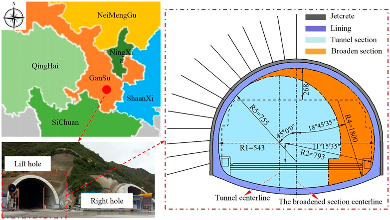
FIGURE 1. Basic information of Gelong Tunnel.
The geological structure of the tunnel site is complex. The surrounding rock is mostly highly-weakly weathered slate, with V-grade surrounding rocks accounting for more than 91.3%, which are relatively fragmented and not suitable for excavation. The surface soil layer is mainly deposited silty clay containing 20%–30% of gravels. The lower layer is highly-weathered slate with layered structure, poorly cemented and partially embedded with weakly weathered rocks. Moreover, the tunnel bottom bedrock is also weakly weathered slate with layered structure, developed fissures and poor stability. Local sections of the tunnel have a large burial depth and belong to high-stress surrounding rock areas. The groundwater is mostly pore-water and bedrock fissure water with a groundwater level ranges from 2.9 m to 27.5 m, which is mainly supplied by vertical infiltration of atmospheric precipitation. During construction, the cavern wall has some dripping water and local seepage. The geological profile is shown in Figure 2 and the soil layer parameters are listed in Table 1.
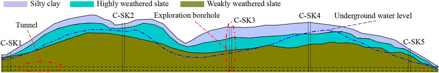
FIGURE 2. Geological profile.
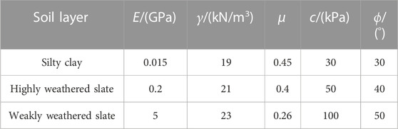
TABLE 1. Soil layer parameters.
The geological conditions of Gelong Tunnel are complex due to the influence of geological structures. The surrounding rock is mainly composed of deposited silty clay containing gravels and Triassic highly-weakly weathered slate. The silty clay and strongly weathered slate have a loose rubbly structure, and the rock mass is fragmented, which results in poor stability during excavation. The on-site construction monitoring and measurement showed that the tunnel is subjected to deformation, cracking during construction. The large deformation mainly concentrated in the arch shoulder and the left arch waist (seeing Figure 3), and the maximum deformation within 80–100 cm.

FIGURE 3. Large deformation and cracking of surrounding rock and initial support. (A) Cracking of surrounding rock during construction. (B) The large deformation of initial support in the arch shoulder and the left arch waist.
Aiming at the problems existing in the project, this paper proposed a CD excavation method based on integrated reinforcement system. The specific reinforcement steps are as follows: 1) Grouting the surrounding rock radially to improve the integrity of surrounding rock; 2) Selecting high-strength steel arches and reducing the spacing between each steel arch; 3) Connecting 3-5 trusses of steel arch frames longitudinally to improve the overall longitudinal stiffness of initial support; 4) Adding additional grouting anchor pipes to each steel arch and temporary support inverted to further control the deformation of surrounding rock; 5) Adjusting the excavation method in time, and adopting the CD method that can quickly and effectively control the deformation of the surrounding rock.
The finite element software MIDAS GTS/NX is adopted to analyze the deformation and stress characteristics of surrounding rock under different working conditions. In order to ensure the reliability of the calculation results, the influence range of tunnel excavation is fully considered. Thus the specific dimensions of the model are X=100 m, Y=120 m and Z=115 m, as shown in Figure 4.

FIGURE 4. 3D finite element model.
The soil and material parameters are obtained according to geological exploration data and laboratory tests, as shown in Table 2.
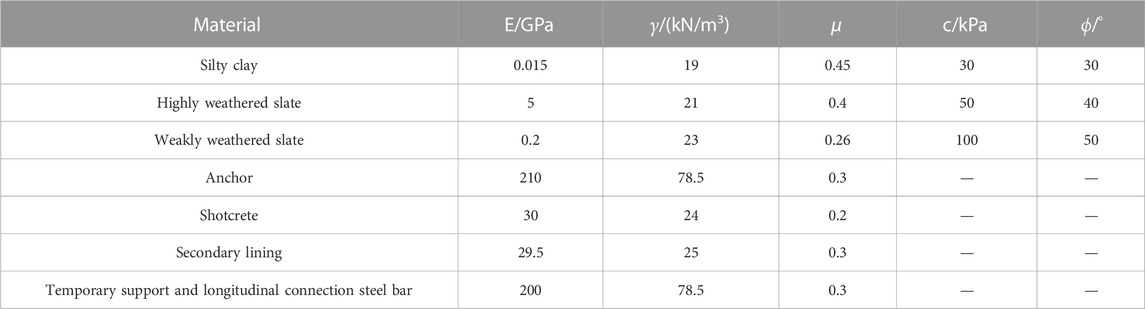
TABLE 2. Calculation parameters used in the model.
The stress and deformation of surrounding rock and support structure shall be strictly monitored during tunnel excavation and support construction. The feasibility of the integrated reinforcement method proposed in this paper is further verified, which ensured the safety and rapid construction of the tunnel.
To keep track of the stress and deformation of the surrounding rock and support structure during tunnel excavation and ensure construction safety, the Earth pressure cells were arranged between the surrounding rock and the initial support, between the initial support and the secondary lining, and the bar stress meters were arranged at the web of the steel arch. The schematic diagram of measuring point layout was shown in Figure 5A, At the same time, the horizontal convergence and vault subsidence monitoring point were placed according to the surrounding rock conditions, as shown in Figure 5B.
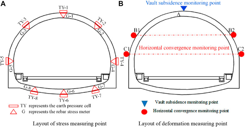
FIGURE 5. Layout of stress and deformation measuring points. (A) Layout of stress measuring point. (B) Layout of defromation measuring point.
Figure 6 shows the arrangement of bar stress meters and Earth pressure cells on-site.
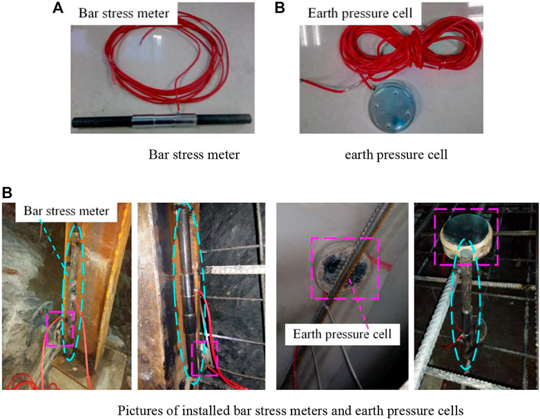
FIGURE 6. Measuring elements and on-site installation.(A) Bar stress meter and Earth pressure cell. (B) Pictures of installed bar stress meters and Earth pressure cells.
This paper compared and analyzed the stress and deformation of tunnel surrounding rock and structure under three-step method and comprehensive reinforcement CD method.
The stress cloud image of surrounding rock under the above two working conditions are shown in Figures 7, 8.
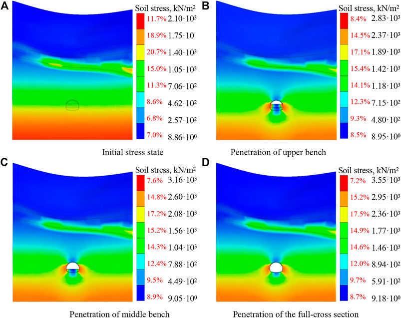
FIGURE 7. Stress of tunnel surrounding rock under three-bench method construction. (A) Initial stress state (B) Penetration of upper bench. (C) Penetration of middle bench (D) Penetration of the full-cross section.
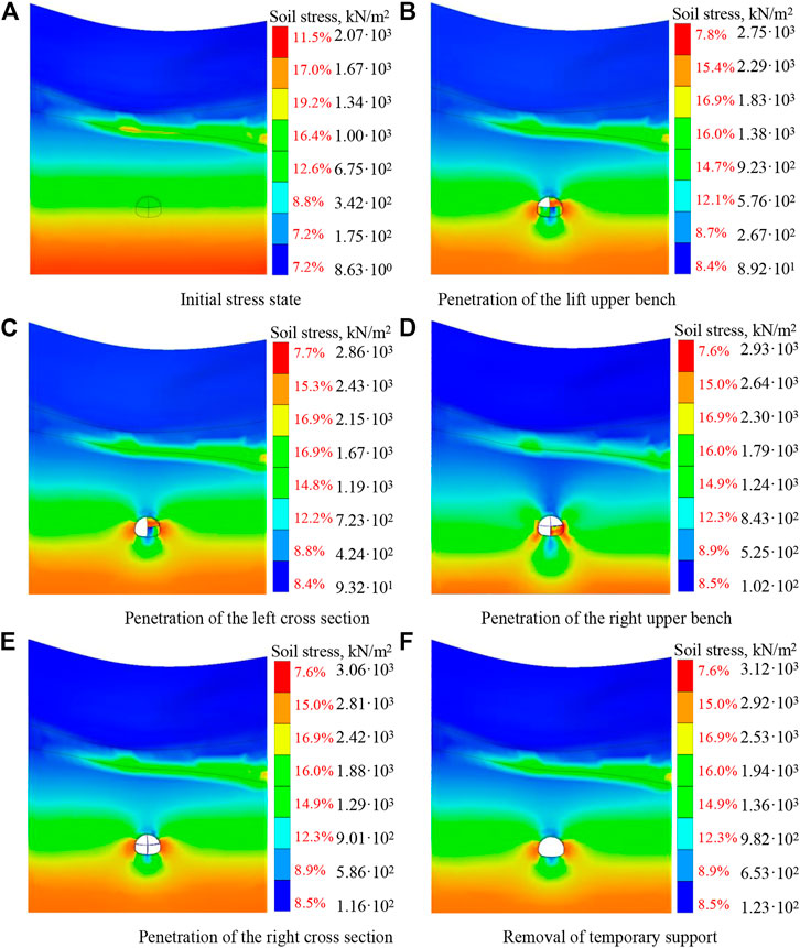
FIGURE 8. Stress of tunnel surrounding rock under CD method construction. (A) Initial stress state (B) Penetration of the lift upper bench. (C) Penetration of the left cross section (D) Penetration of the right upper bench. (E) Penetration of the right cross section (F) Removal of temporary support.
Figure 7B showed that the stress concentrated at the left and right arches after upper bench excavation, and the maximum stress was 2.83 MPa. After the middle bench is excavated, the stress was mainly distributed in the arch waist, arch foot and side wall. And the stress was roughly symmetrical on both sides, with the maximum stress appeared in the left wall, about 3.16 MPa, as shown in Figure 7C. After the excavation of lower bench and the addition of secondary lining, the stress of the structure was still mostly concentrated in the arch waist, arch foot and side wall, with the stress release ratios were about 80% 10% and 10%, and the maximum stress was 3.55 MPa, as shown in Figure 7D.
It can be seen from Figure 8 that during soil excavation at the left upper bench, the stress gradually concentrated at the left arch foot, with a maximum of 2.75 MPa. After the excavation of the left lower bench, the large stress was mainly concentrated in the arch waist, arch foot and side wall on the left side. In addition, a large stress appeared at the temporary support arch foot for the right upper bench, with the value of 2.86 MPa. With the removal of the temporary support and the construction of secondary lining, the response range of surrounding rock stress dwindled and eventually stabilize. This indicated that the stress was basically released and the maximum stress was 3.12 MPa, as shown in Figure 8D. The comparative analysis of Figures 7, 8 showed that the stress distribution range of surrounding rock under the two working conditions was about 1.5 D (20 m), and the stress levels were roughly the same. After the tunnel penetrated, the maximum stress in the three-bench method was 3.55 MPa, which was 0.43 MPa higher than that in the CD method.
To better understand the control effect of different construction methods (three-bench method and CD method) on the large deformation of surrounding rock, the variation curves of vault settlement and horizontal convergence of surrounding rock during the construction are drawn, as shown in Figure 9.
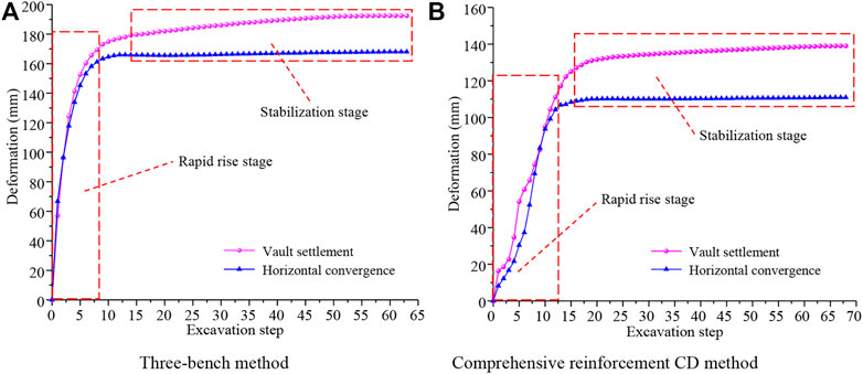
FIGURE 9. Deformation curves of surrounding rock under two working conditions. (A) Three-bench method (B) CD method.
It is obvious from Figure 9 that the surrounding rock deformation can be well controlled by reasonable selection of construction method. As shown in Figure 9A, in the first 10 excavation steps, the vault settlement and horizontal convergence deformation increased rapidly to 172.5 mm and 161.3 mm owing to excavation of the soil, accounting for 89.6% and 95.9% of the total deformation, respectively. This indicated that the release of soil constraint had a significant effect on the stability of surrounding rock. With the construction of inverted arch frame and lining structure, the vault settlement and horizontal convergence gradually increased after the 15th excavation step (the whole tunnel section was excavated), which tended to stabilize around the 30th step with the stayed value of 192.5 and 168.1 mm respectively. As shown in Figure 9B, the deformation rate of surrounding rock in the first 10 excavation steps was obviously lower than that in the three-bench method. However, the deformation was still developing rapidly, and the vault settlement and horizontal convergence surged to 99.4 mm and 98.1 mm, accounting for 66.9% and 88.5% of the total deformation, respectively. Due to the construction of temporary support and inverted arch, there were several deformation fluctuations. Subsequently, with the construction of the integrated reinforcement system and the lining structure, the deformation of the surrounding rock in the 10th to 15th excavation steps showed an obvious inflection point. After the 20th excavation step, the deformation tended to be stabilize. The vault settlement and horizontal convergence finally stabilized at 148.6 and 110.9 mm, respectively. This demonstrated the excellent effect of the integrated reinforcement CD method on controlling the deformation of surrounding rock. The specific results of the two methods are presented in Table 3.

TABLE 3. Comparison of surrounding rock stress and deformation.
It can be seen from Table 3 that the CD method outperformed greatly the three bench method in controlling the deformation of surrounding rock. It reduced the vault settlement and horizontal convergence deformation by 27.8% and 34.0%, respectively, and the surrounding rock deformation tended to be stable faster. For the structural stress, the stress on the second lining structure in the case of CD method was small, and the maximum stress was 13.8 lower than that of the three-bench method. In conclusion, the CD method can better control the large deformation of surrounding rock during the construction of large-section soft rock tunnel.
On the basis of the CD method, measures such as reducing spacing and strengthening the longitudinal connection of steel arch frame, adding a feet-lock anchor pipe and a temporary inverted arch were adopted to constrain the surrounding rock deformation and ensure the construction safety. The site implementation of the reinforcement measures is shown in Figure 10.
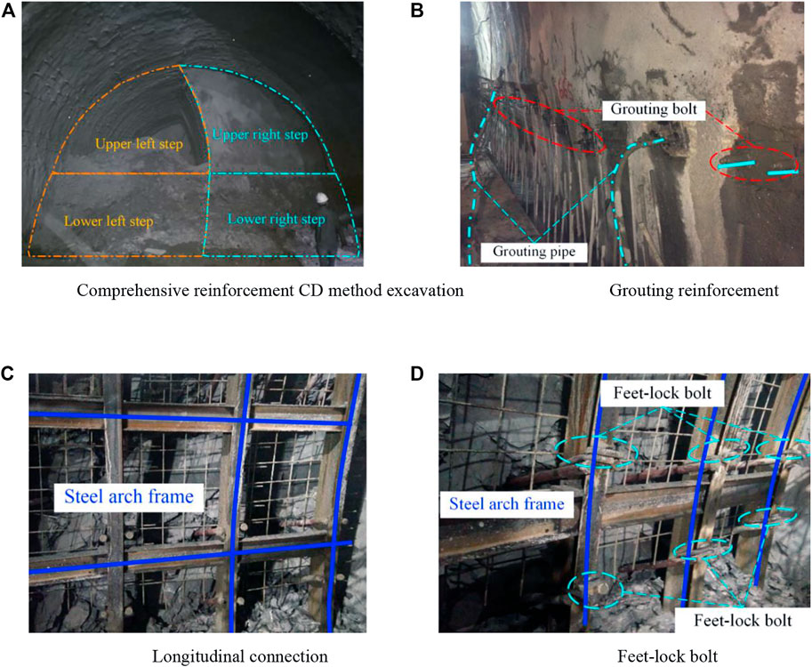
FIGURE 10. Comprehensive reinforcement CD method construction and supporting structure. (A) CD method excavation. (B) Grouting reinforcement. (C) Longitudinal connection (D) Feet-lock bolt.
Based on the measured data of ZK253+860 section (V-grade surrounding rock) at the Gelong Tunnel entrance, the deformation characteristics of surrounding rock and the stress variation of supporting structures were analyzed to verify the effectiveness of the proposed method.
Figure 11 showed the time-history curves of the accumulated deformation and deformation rate of surrounding rock.
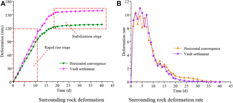
FIGURE 11. Surrounding rock deformation. (A) Surrounding rock deformation (B) Surrounding rock deformation rate.
It can be seen from Figure 11 that the deformation rate of the surrounding rock was relatively large in the first 11 days of excavation. The vault settlement and horizontal convergence were 116.9 and 97.9 mm respectively, accounting for 73.53% and 76.62% of the total deformation. In the following 12–18 days, the deformation rate declined significantly due to the construction of the integrated reinforcement system. After the 20th day, the deformation tended to be stable and the vault settlement and horizontal convergence finally stabilized at 159.1 and 127.9 mm respectively. The measured results were slightly larger than the numerical results (as shown in Figure 9B) due to uncertainties in the construction, while, the difference between them was quite small. The surrounding rock deformation in both results tended to stabilize in roughly the same time, indicating that the CD method proposed in this paper was feasible and very effective.
The real-time axial force of the steel arch frame at the ZK253+860 section were collected, based on which the time-history variation curve was drawn (positive for tension and negative for compression), as shown in Figure 12.

FIGURE 12. Time-history curve of axial force of steel arch frame at section ZK253+860.
It can be seen from Figure 12 that the steel arch frame was subjected to tension in the whole process at the vault (G1), the right spandrel (G2) and the right side of inverted arch (G7). At the initial stage, the tensile stress rose in a roughly straight line. Among them, the vault bore the largest tensile stress of 2775 kN, which stabilized at about 1500 kN after 16d. The steel arch frame was subjected to compressive stress at the left (G8) and middle (G6) of the inverted arch throughout the whole process, and the peak values of the two were relatively close. The maximum was 1250 kN, which basically stabilized at about 1500 kN after 27d. In the initial stage, the other parts of the steel arch were mainly subjected to tension. After the deformation of the surrounding rock lasted for about 12d, the steel arch began to bear a small compressive stress. From the stress distribution, the steel arch frame at the left half of the tunnel arch was subjected to larger stress, which was completely consistent with the deformation of the surrounding rock. At the same time, under the strong support of the integrated reinforcement system, the axial force of the steel arch frame was rapidly stabilized.
To investigate the stress characteristics of the supporting structure under the action of the integrated reinforcement system, the stress of initial support and secondary lining at section (ZK253+860) were collected. And the time-history characteristic curves of the stress variation were drawn, as shown in Figure 13.
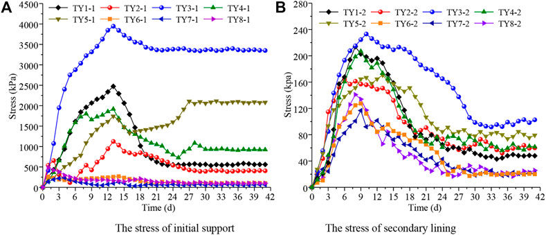
FIGURE 13. Time-history characteristic curves of surrounding rock stress on supporting structures. (A) The stress of initial support (B) The stress of secondary lining.
As can be seen from Figure 13, the surrounding rock stress on the supporting structures was generally large, which gradually stabilized after 25d of tunnel excavation. The proportion of initial support and secondary lining to bear the surrounding rock stress was about 8.9:1.1. It can be observed from Figure 13A that the initial support was subjected to uneven stress. Specifically, the pressure at the vault, left shoulder and right wall was large and the growth rate was fast. And they all reached the extreme values about 12 days after excavation, which were 2472 kPa, 39544 kPa, and 1916 kPa respectively. The left wall suddenly surged to a maximum on the 24th day and basically remained at 1743 kPa. With the continuous release of surrounding rock stress and the construction of comprehensive reinforcement system, the surrounding rock stress gradually tended to be stable. As can be seen from Figure 13B, the stress on the second lining also showed a trend of first increasing and then decreasing. However, the overall stress was far less than that on the initial support, and its maximum appeared at the left spandrel, which was only 233 kPa. Due to the strong bearing capacity of initial support, the surrounding rock stress born by the secondary lining was very small and evenly distributed. This proved that the initial support was of great significance to the safety of secondary lining structure, and that the proposed CD method could significantly reduce large deformation of soft rock tunnel.
Figure 14 shows the distribution of maximum stress of surrounding rock and secondary lining. It can be observed that the surrounding rock stress on the initial support was unevenly distributed, large on the left and small on the right. In particular, the vault, left spandrel, and left side wall bore larger stress and were prone to deformation and collapse, which was completely consistent with the field disaster situation.
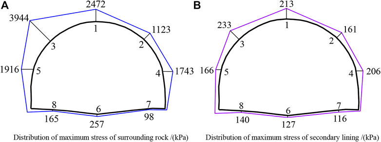
FIGURE 14. Distribution of maximum stress of surrounding rock and secondary lining. (A) Distribution of maximum stress of surrounding rock/(kPa) (B) Distribution of maximum stress of secondary lining/(kPa).
In view of the large deformation of surrounding rock during the construction of large-section tunnel in soft rock strata, this paper conducted a case study based on Gelong Tunnel passing through carbonaceous slate. Through theoretical analysis and numerical simulation, this paper proposed the CD method with integrated reinforcement to control the large deformation of surrounding rock, and verified by on-site monitoring results. The main conclusions were as follows:
(1) The CD excavation method supplemented by strengthening the longitudinal stiffness of the supporting structure and the integrity of the surrounding rock can well control the large deformation of soft rock tunnel. The vault settlement and convergence deformation of surrounding rock under CD method reduced by 27.8% and 34.0% respectively than three-bench method, and the value of stress on second lining structure was 13.8%, which could provide reference for the design and construction of similar projects.
(2) The surrounding rock deformation was large in the early stage, and the vault settlement and horizontal convergence were 116.9 and 97.9 mm respectively, accounting for 73.53% and 76.62% of the total deformation. The deformation rate declined significantly due to the construction of the integrated reinforcement system. The vault settlement and horizontal convergence finally stabilized at 159.1 mm and 127.9 mm respectively, indicating that the proposed method was feasible and effective in controlling the large deformation of surrounding rock.
(3) The steel arch frame was subjected to tension in the whole process at the vault, the right spandrel and the right side of the inverted arch, and the vault bore the largest tensile stress of 2775 kN. By contrast, the steel arch frame was subjected to compressive stress at the left and middle of the inverted arch throughout the whole process, and the maximum was 1250 kN. For the stress distribution, the steel arch frame at the left half of the tunnel arch was subjected to larger stress, which was completely consistent with the deformation of the surrounding rock.
(4) The surrounding rock stress on the supporting structures was generally large, and the proportion of initial support and secondary lining to bear the surrounding rock stress was about 8.9:1.1. The surrounding rock stress acting on the initial support was large on the left and small on the right. The stress on the second lining was evenly distributed and much smaller than that on the initial support, with the maximum of 120 kPa. This demonstrated that the initial support was of great significance to the safety of secondary lining structure, and the proposed CD method could significantly control the large deformation of soft rock tunnel.
The original contributions presented in the study are included in the article/Supplementary Material, further inquiries can be directed to the corresponding authors.
ZN, overall control of the article research methods, indoor and outdoor tests and theoretical calculations. YW, theoretical calculation guide. SF, outdoor test data acquisition.
The present work was subsidized and supported by the National Natural Science Foundation of China (No. 52178393; No. 51578447), the Science and Technology Innovation Team of Shaanxi Innovation Capability Support Plan (No. 2020TD005), the Science and Technology Development Program of Shaanxi Provincial Department of Housing and Urban-rural Construction (No. 2019-K39), and the Special Project of Shaanxi Provincial Education Department (No. 20JK0709).
The financial supports are gratefully acknowledged and the data is available for the journal.
ZN was employed by XAUAT Engineering Technology Co., Ltd.
The remaining authors declare that the research was conducted in the absence of any commercial or financial relationships that could be construed as a potential conflict of interest.
All claims expressed in this article are solely those of the authors and do not necessarily represent those of their affiliated organizations, or those of the publisher, the editors and the reviewers. Any product that may be evaluated in this article, or claim that may be made by its manufacturer, is not guaranteed or endorsed by the publisher.
Bian, K., Liu, J., Liu, Z. P., Liu, S. G., Ai, F., Zheng, X. Q., et al. (2019). Mechanisms of large deformation in soft rock tunnels: A case study of huangjiazhai tunnel. B Eng. Geol. Environ. 78 (1), 431–444. doi:10.1007/s10064-017-1155-8
Chen, F., Tang, C. A., Sun, X. M., Ma, T. H., and Du, Y. H. (2019a). Supporting characteristics analysis of constant resistance bolts under coupled static-dynamic loading. J. Mt. Sci-Engl 16 (5), 1160–1169. doi:10.1007/s11629-018-5044-9
Chen, Z. Q., He, C., Xu, G. W., Ma, G. Y., and Wu, D. (2019b). A case study on the asymmetric deformation characteristics and mechanical behavior of deep-buried tunnel in phyllite. Rock Mech. Rock Eng. 52 (11), 4527–4545. doi:10.1007/s00603-019-01836-2
Dutta, P., and Bhattacharya, P. (2022). Stability of rectangular tunnels in weathered rock subjected to seepage forces. Arab. J. Geosci. 15 (1), 61. doi:10.1007/s12517-021-08817-2
Fan, S. Y., Song, Z. P., Zhang, Y. W., and Liu, N. F. (2020). Case study of the effect of rainfall infiltration on a tunnel underlying the roadbed slope with weak inter-layer. KSCE J. Civ. Eng. 24 (5), 1607–1619. doi:10.1007/s12205-020-1165-0
Froech, G., Flora, M., Gaechter, W., Harpf, F., and Tautschnig, A. (2019). Application possibilities of a digital ground model in tunnel construction. Bautechnik 96 (12), 885–895. doi:10.1002/bate.201900080
Guo, K., Xu, Y. P., and Li, J. F. (2018). Thrust force allocation method for shield tunneling machines under complex load conditions. Autom. Constr. 96, 141–147. doi:10.1016/j.autcon.2018.08.016
Guo, X. L., Zhu, Y. Q., Tan, Z. S., Li, L., Li, A., and Yan, Y. T. (2021). Research on support method in soft rock tunnel considering the rheological characteristics of rock. Arab. J. Geosci. 14 (3), 2703. doi:10.1007/s12517-021-08635-6
Hu, Z. P., An, X. X., Li, F. T., and Zhang, Y. H. (2022). The shape characteristics of circular tunnel surrounding rock plastic zone in the complex stress field. Arab. J. Geosci. 15 (2), 150. doi:10.1007/s12517-021-08567-1
Jia, J. Q., Tenorio, V. O., Zhang, B. X., Li, M. Z., and Xin, C. P. (2022). Stability and reliability of a shallow tunnel in soft surrounding rock: Construction technology and prediction. Arab. J. Geosci. 15 (3), 289. doi:10.1007/s12517-022-09428-1
Lei, D. X., Xie, L. L., and Wu, L. (2022). Three-dimensional collapse mechanism and failure probability analysis of deep-buried tunnel based on the upper bound theorem of limit analysis and Hoek-Brown failure criterion. Arab. J. Geosci. 15 (2), 139. doi:10.1007/s12517-021-09392-2
Li, B., Ding, Q. F., Xu, N. W., Lei, Y. F., Xu, Y., Zhu, Z. P., et al. (2021). Erratum to: Mechanical response and stability analysis of rock mass in high geostress underground powerhouse caverns subjected to excavation. J. Cent. South Univ. 28 (3), 982. doi:10.1007/s11771-021-4659-0
Li, Y. H., Wang, H. L., Zhao, Y., and Dong, J. (2022). Prediction of the vibration waveform of surface particles under the action of tunnel cutting blast. Arab. J. Geosci. 15 (1), 38. doi:10.1007/s12517-021-09311-5
Liu, D. P., Zhang, D. L., Fang, Q., Sun, Z. Y., Luo, J. W., and Li, A. (2020). Field monitoring of the deformation and internal forces of the surrounding rock and support structures in the construction of a super-span high-speed railway tunnel-A case study. Appl. Sci-Basel 10 (15), 5182. doi:10.3390/app10155182
Liu, N. F., Li, N., Li, G. F., Song, Z. P., and Wang, S. J. (2022). Method for evaluating the equivalent thermal conductivity of a freezing rock mass containing systematic fractures. Rock Mechanics and Rock Engineering 55 (12), 7333–7355. doi:10.1007/s00603-022-03038-9
Lv, J. B., Li, X. L., Li, Z. R., and Fu, H. L. (2019). Numerical simulations of construction of shield tunnel with small clearance to adjacent tunnel without and with isolation pile reinforcement. KSCE J. Civ. Eng. 24 (1), 295–309. doi:10.1007/s12205-020-1167-y
Niu, Z. L., Cheng, Y., Zhang, Y. W., Song, Z. P., Yang, G. Y., and Li, H. (2020). A new method for predicting ground settlement induced by pipe jacking construction. Math. Probl. Eng. 2020, 1–11. doi:10.1155/2020/1681347
Niu, Z. L., Xu, J., Li, Y. F., Wang, Z. F., and Wang, B. (2021). Strength deterioration mechanism of bentonite modified loess after wetting-drying cycles. Scientifc Reports, 1–17. doi:10.1038/s41598-022-06962-6
Parisio, F., Vilarrasa, V., and Laloui, L. (2018). Hydro-mechanical modeling of tunnel excavation in anisotropic shale with coupled damage-plasticity and micro-dilatant regularization. Rock Mech. Rock Eng. 51 (12), 3819–3833. doi:10.1007/s00603-018-1569-z
Qin, Y. W., Lai, J. X., Yang, T., Zan, W. B., Feng, Z. H., and Liu, T. (2022). Failure analysis and countermeasures of a tunnel constructed in loose granular stratum by shallow tunnelling method. Engineering Failure Analysis 141, 106667. doi:10.1016/j.engfailanal.2022.106667
Song, Z. P., Cheng, Y., Tian, X. X., Wang, J. B., and Yang, T. T. (2020). Mechanical properties of limestone from Maixi tunnel under hydro-mechanical coupling. Arab. J. Geosci. 13 (11), 402. doi:10.1007/s12517-020-05373-z
Song, Z. P., Shi, G. L., Zhao, B. Y., Zhao, K. M., and Wang, J. B. (2019). Study of the stability of tunnel construction based on double-heading advance: Construction method. Adv. Mech. Eng. 12 (1), 168781401989696. doi:10.1177/1687814019896964
Tian, X. X., Song, Z. P., and Wang, J. B. (2019). Study on the propagation law of tunnel blasting vibration in stratum and blasting vibration reduction technology. Soil Dyn. Earthq. Eng. 126, 105813. doi:10.1016/j.soildyn.2019.105813
Xie, Z. Z., Zhang, N., Feng, X. W., Liang, D. X., Wei, Q., and Weng, M. Y. (2019a). Investigation on the evolution and control of surrounding rock fracture under different supporting conditions in deep roadway during excavation period. Int. J. Rock Mech. Min. 123, 104122. doi:10.1016/j.ijrmms.2019.104122
Yao, Y., Lai, H. P., Zhang, Q., and Liu, Y. Y. (2021). Prediction of plastic and fractured zone extent around deep circular tunnel subjected to spatial constraint effect. Arab. J. Geosci. 14 (20), 2098. doi:10.1007/s12517-021-08428-x
Yu, W. J., and Li, K. (2020). Deformation mechanism and control technology of surrounding rock in the deep-buried large-span chamber. Geofluids 2020, 1–22. doi:10.1155/2020/8881319
Zhang, H., Chen, L., Zhu, Y. M., Zhou, Z. L., and Chen, S. G. (2019). Stress field distribution and deformation law of large deformation tunnel excavation in soft rock mass. Appl. Sci-Basel 9 (5), 865. doi:10.3390/app9050865
Zhang, Q., Song, Z. P., Li, X. L., Wang, J. B., and Liu, L. J. (2019). Deformation behaviors and meso-structure characteristics variation of the weathered soil of Pisha sandstone caused by freezing-thawing effect. Cold Reg. Sci. Technol. 167, 102864. doi:10.1016/j.coldregions.2019.102864
Zhang, Y. W., Fan, S. Y., Yang, D. L., and Zhou, F. (2022a). Investigation about variation law of frost heave force of seasonal cold region tunnels: A Case Study. Front. Earth Sci 9, 806843. doi:10.3389/feart.2021.806843
Zhang, Y. W., Song, Z. P., and Weng, X. L. (2022b). A constitutive model for loess considering the characteristics of structurality and anisotropy. Soil Mechanics and Foundation Engineering 59 (1), 32–43. doi:10.1007/s11204-022-09781-z
Keywords: large-section highway tunnel, highly-weakly weathered slate, comprehensive reinforcement CD method with integrated reinforcement, deformation control, surrounding rock pressure
Citation: Niu Z, Wang Y and Fan S (2023) Research on the deformation control of surrounding rock about large-section tunnel in strong-medium weathered slate. Front. Earth Sci. 10:1094325. doi: 10.3389/feart.2022.1094325
Received: 10 November 2022; Accepted: 20 December 2022;
Published: 09 January 2023.
Edited by:
Ping Zhang, Luleå University of Technology, SwedenCopyright © 2023 Niu, Wang and Fan. This is an open-access article distributed under the terms of the Creative Commons Attribution License (CC BY). The use, distribution or reproduction in other forums is permitted, provided the original author(s) and the copyright owner(s) are credited and that the original publication in this journal is cited, in accordance with accepted academic practice. No use, distribution or reproduction is permitted which does not comply with these terms.
*Correspondence: Zelin Niu, bml1emxkcUB4YXVhdC5lZHUuY24=; Yaqiong Wang, eXMwOEBnbC5jaGQuZWR1LmNu
Disclaimer: All claims expressed in this article are solely those of the authors and do not necessarily represent those of their affiliated organizations, or those of the publisher, the editors and the reviewers. Any product that may be evaluated in this article or claim that may be made by its manufacturer is not guaranteed or endorsed by the publisher.
Research integrity at Frontiers
Learn more about the work of our research integrity team to safeguard the quality of each article we publish.