 Jianyong Han1,2
 Jun Wang1Cheng Cheng3*
 Chaozhe Zhang4*Erbin Liang5Zhikang Wang5Jae-Joon Song1,6Junsu Leem6
- 1School of Civil Engineering, Shandong Jianzhu University, Jinan, China
- 2Key Laboratory of Building Structural Retrofitting and Underground Space Engineering, Ministry of Education, Shandong Jianzhu University, Jinan, China
- 3School of Rail Transportation, Soochow University, Suzhou, Jiangsu, China
- 4School of Transportation, Southeast University, Nanjing, Jiangsu, China
- 5China Railway Fourteenth Bureau Group Co, Ltd., Jinan, Shandong, China
- 6Department of Energy Resources Engineering, Research Institute of Energy and Resources, Seoul National University, Seoul, Korea
The existing Beijing Pingguoyuan Subway Station was extended through a extension project. The excavation for the extension was located directly above the existing station. Complex interactions exist between the existing structure and the retaining pile wall of the excavation. Based on this project, three-dimensional finite element models were established to investigate the mechanical characteristics of the embedded and non-embedded retaining pile walls. A parametric analysis was performed for both types of pile walls. The stress and deformation characteristics of the retaining pile walls and existing structures were analyzed. The results show that when the bottom of the non-embedded retaining pile walls are connected to the existing structure, the uplift of the existing structure is essentially constant; however, the maximum displacement of the pile is increased by approximately 2.7 times, and the bending moment of the pile is reduced to 57.1% of the connection condition. As the distance between the embedded retaining pile wall and the existing station increases, the uplift of the existing station increases linearly, whereas the soil between the pile and the station exhibits a non-linear increasing trend. The displacement of the embedded retaining pile wall increases as the inner force decreases. When the distance is greater than 4.7 m, the displacement and force of the pile remains essentially unchanged. The effect of the pile embedded depth on the force and deformation of the pile is mainly observed in the lower part of the pile. As the embedded depth increases, the maximum displacement decreases by approximately 16.9%, the maximum bending moment decreases, and the maximum negative bending moment increases. The key contribution of this research is to provide a prediction method for the mechanical behaviors of a expansion project. The findings from the study also provide industry practitioners with a comprehensive guide regarding the specific applications of the construction technology of a deep excavation structure overlying an existing subway station.
Introduction
The National Innovation-Driven Development Strategy, recently proposed by China, has highlighted the need for network-based development of underground spaces to fulfill modern city development needs (Cui and Nelson, 2019; Cui et al., 2021; Li et al., 2022). Consequently, constant improvements in construction methods and the emergence of new technical solutions have facilitated the expansion of many domestic underground projects (Song et al., 2020b; Huang et al., 2021). In particular, the expansion of subway stations through the addition of new superstructures to existing underground structures has proven economically advantageous (Xu et al., 2020; Liu et al., 2022). However, in the case of such expansion projects, large-scale excavation and the consequent unloading significantly impacts the existing subway structure. Moreover, because part of the retaining wall structure of the deep excavation is connected to the existing subway structure, its mechanical behavior and effect on the surroundings differ from that of a conventional deep excavation. Therefore, the expansion process involves more complex design and construction methods than those required for conventional deep excavations of adjacent structures. In this context, limited research has been conducted on the expansion of existing underground structures. In particular, more research and in-depth analyses are required to elucidate the mechanical interaction between the deep excavation of the superstructure and the existing underground structure because such investigations can provide a more comprehensive theoretical basis for this type of construction project.
As early as the 1970s and 1980s, Peck and Clough et al. (Peck, 1969; Clough and O'Rourke, 1990) summarized the common types of deformation of deep excavations based on their analysis of various observation results. Moreover, they conducted a comparative analysis of the surface subsidence trends of different retaining walls, and ultimately proposed an empirical curve for predicting the amount and range of surface subsidence. Based on a comparison of the results obtained from finite difference numerical simulations and extreme equilibrium methods, Zheng et al. and Zhao et al. (2018) (Gang et al., 2017; Han et al., 2017) analyzed the failure mode of deep excavation and the beneficial effects of foundation piles on excavation stability. They indicated that the failure mode of a deep excavation is similar to that of a circular slip surface. In addition, the findings demonstrated that foundation piles effectively restrict the expansion of the plastic shear zone of the deep excavation. However, most of aforementioned studies focused on deep excavations at sites with few surrounding structures. In actuality, the complex interactions between deep excavation and existing structures are significant and require needs further study. Han et al. (Han et al., 2020) established a finite element model using the PLAXIS program to analyze the effects of constructing a deep excavation adjacent to shallow buried-foundation structures on the deformation of the retaining structures of the deep excavation and adjacent structures. They presented the primary and secondary influence zones behind the retaining structure of the deep excavation based on the potential failure zone. Zhou et al. and Cheng et al. (Zelin et al., 2015; Caide et al., 2017; Kang et al., 2020) analyzed the impact of deep excavation construction on the uplift deformation of an existing subway tunnel. A method for calculating the additional stress in an adjacent tunnel caused by deep excavation construction and dewatering was proposed. Some researchers (Tan and Lu, 2018; Masini et al., 2021) studied the field performance of deep excavations with short distances with the existing structures through case studies. The researches on the deep excavation adjacent to the existing structures have well proven that the deep excavation has significant interaction with the adjacent existing structure. However, these studies focus on the cases that there is a distance between the deep excavation and the existing structure. The mechanical behaviors of deep excavations for expansion project need further investigations.
Thus, the expansion project of Pingguoyuan Subway Station, part of the West Extension Project of Beijing Subway Line 6, was researched as a case study. A parametric analysis of the primary parameters of the embedded and non-embedded piles of the deep excavation was conducted. The mechanical behaviors of the retaining pile walls of the deep excavation and t adjacent existing subway station under different parameter conditions were revealed. As a study outcome, the optimal parameters influencing the deep excavations of an expansion project are recommended. We believe that the results of this study can provide theoretical guidance for similar expansion projects.
Beijing subway station expansion project
Project overview
The Pingguoyuan subway station (see Figure 1A), newly built along Beijing Subway Line 6, was constructed below the existing structure of Beijing Subway Line 1 with the two lines crossing at an oblique angle of 70°, which was shown in Figure 1B. The station’s main structure was constructed using the pile–beam–arch (PBA) and open-cut methods. The two expansion sections are located on the eastern and western sides of the existing Subway Line 1 (see Figure 1C). As part of the expansion project, the second and third underground levels were constructed using the PBA method, while the first underground level was constructed using the open-cut method, which was for transfer between the two lines. The first underground level was constructed after the construction of the second and third underground levels completed. The two deep excavations for the expansion structures had the same dimensions of 39.8 m long (east to west), 27.9 m wide (north to south), and 12.2 m deep. The retaining wall of the deep excavations consisted of 1 m-diameter bored piles positioned at a spacing of 1.6 m and three levels of struts. In addition, a 100 mm layer of mesh-reinforced shotcrete was used to reinforce the space between the piles. The corner struts of the first level were concrete struts with cross-sectional dimensions of 0.6 m × 1 m, and the remaining struts were designed as steel pipe struts with a diameter of 0.8 m and a thickness of 16 mm.
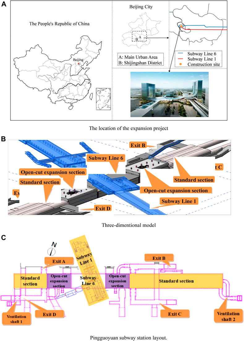
FIGURE 1. The diagram of Beijing Subway Station expansion project. (a) The location of the expansion project; (b) Three-dimentional model; (c) Pingguoyuan subway station layout.
Deep excavation retaining structure
Considering that the excavation was located above the existing station structure, the retaining piles on the eastern and western sides of the deep excavation were positioned directly above the existing structure. Thus, the piles in these areas were end-suspended piles (hereafter referred to as “non-embedded piles,” NEP). The piles on the northern and southern sides of the deep excavation were embedded into the soil at a certain depth. These piles (hereafter referred to as “embedded piles,” EP) were adjacent to the side walls of the pilot tunnels of the existing station structure. The minimum distance between an embedded pile and the pilot tunnel wall was 0.2 m. The different retaining structures are denoted as follows: A indicates a NEP, B indicates an EP, L1–L3 indicate the three respective levels of struts, and He denotes the excavation depth of the deep excavation, as shown in Figures 2, 3.
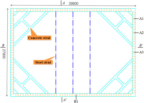
FIGURE 2. Plan view of the deep excavation structure.
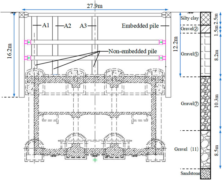
FIGURE 3. Profile of the deep excavation structure (AA' in Figure 2).
To ensure the deep excavation was stable, the bottom of the NEP was connected to the existing structure. When the bore hole reached the pilot tunnel of the existing station, a pneumatic drill was used to remove a 200 mm thick concrete layer from the pilot tunnel. By destroying part of the concrete of the pilot tunnel, the reinforcement was exposed. Subsequently, the bottom of the reinforcement cage of the piles and the exposed reinforcement of pilot tunnel structure were welded. And then, the pile concrete was poured into the pile holes. Based on aforementioned treatment, the non-embedded piles were embedded into the pilot tunnel (see Figure 4). In addition, to ensure the ground behind the non-embedded piles was stable, the ground was reinforced with a 3-m thick grout layer behind the piles, from the bottom of the deep excavation to a depth of 3.7 m below the ground surface (see Figure 5).
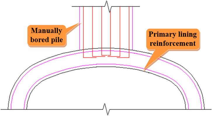
FIGURE 4. Connection between the retaining pile and primary lining of the pilot tunnel.
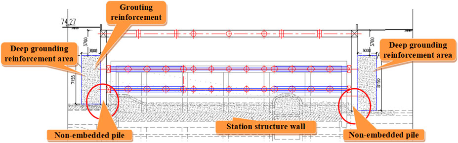
FIGURE 5. Profile of the deep excavation structure (B–B' in Figure 2).
Horizontal deformation of the retaining piles
In this study, the horizontal displacement of the retaining piles was observed in situ using inclinometers inside the pile wall. Observations from the inclinometers of retaining piles A2 and B1 were selected for the analysis. Figure 6 shows the horizontal displacement curves for piles A2 and B1. Figure 6A shows that the horizontal displacement at the bottom of the non-embedded pile (A2) is equal to zero, thereby indicating that the connection between the pile bottom and the existing structure effectively limited pile bottom the deformation. A comparison of Figures 6A,B reveals that the horizontal displacement of the EP was smaller than that of the NEP. Grouting reinforcement effectively reduced the displacement of the piles. For both types of piles, the maximum horizontal displacement occurred after the third level of struts was removed. The maximum horizontal displacement was approximately 4.50 mm, which is approximately 0.037% of the excavation depth of the deep excavation. These results indicate that the connection between the pile bottom and primary lining structure of the pilot tunnel, grouting reinforcement, and strut supports effectively restrained the pile deformation.
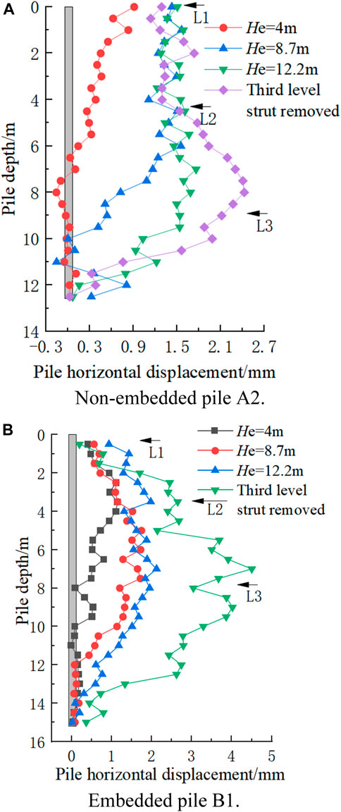
FIGURE 6. Horizontal displacement curve of retaining piles. (a) Non-embedded pile A2; (b) Embedded pile B1.
Numerical model of the deep excavation of subway extension project
Model establishment
According to the available literature (Xiaogang, 2016), when a pile bottom is not embedded, the range of influence of the deep excavation on the surroundings is approximately 1.5He. Based on this value and a certain extent of expansion, the boundary of the numerical model was set as 3.3He in the horizontal direction and 2He in the downward vertical direction from the station structure. Thus, the dimensions of the finite element model were set as 119 × 105 × 55 m (see Figures 7, 8). The boundary conditions of the numerical model include the stress and seepage boundaries (Yingren and Shangyi, 2005; Yong and Jianyong, 2005; Zhou et al., 2021; Wang et al., 2022). However, the groundwater level was located 10.4 m below the bottom surface of the existing station. Therefore, the seepage was not considered in the numerical model. The top surface of the model was a free surface with no constraints. The lateral surfaces were constrained in the horizontal direction, and the bottom surface was constrained in the horizontal and vertical directions. After considering the weight of the modeled materials, the construction loads around the deep excavation were adopted, with a uniformly distributed load of 20 kPa in the range of 2–10 m behind the retaining piles.
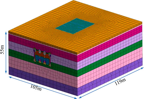
FIGURE 7. Finite element model of the deep excavation above an existing structure.
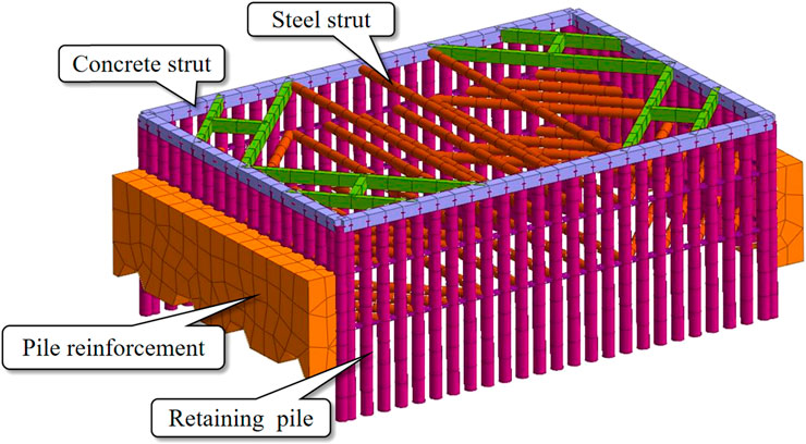
FIGURE 8. Model of the retaining structures of the deep excavation.
Parameter determination
In the numerical model, different elements were selected to represent the mechanical characteristics of the various materials. The soil materials and existing station were modeled using solid elements, and the primary lining structure of the pilot tunnel was modeled using plate elements. The retaining pile walls, cap beams, concrete struts, and steel pipe columns were modeled using beam elements (Song et al., 2020a; Chen et al., 2021). The steel struts were modeled using truss elements. The mechanical characteristics of the grouting reinforcement area were simulated by modifying the element attributes of this area between the soil and grout–soil mixture. A linear elastic constitutive model was used to simulate the materials, except for the soils. The primary mechanical properties of the materials used in the model are listed in Table 1.
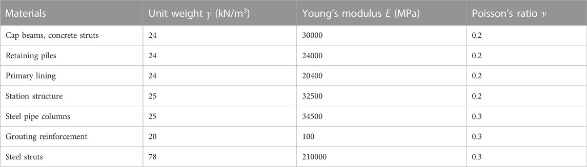
TABLE 1. Mechanical properties of the model materials.
It is established that deep excavations involve the unloading of large volumes of soil, and therefore, the deformation behaviors of deep excavations are sensitive (Shuling et al., 2008). Therefore, the silty-clay and gravel soil in the numerical model were simulated using the Hardening Soil (HS) model. According to the PLAXIS user manual, the HS model is a more advanced soil model for different soil behaviors than the Mohr–Coulomb (MC) model, which adopts a hyperbolic stress−strain representation for soils (see Figure 9). The stiffness parameters in the HS model consist of three stress-dependent stiffness parameters,
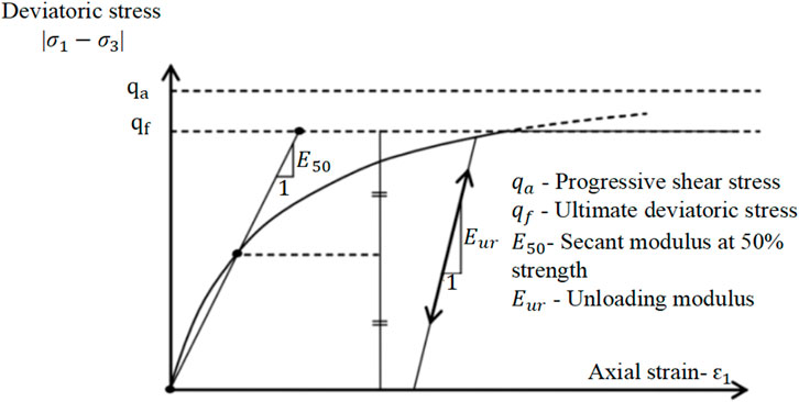
FIGURE 9. Hyperbolic stress–strain relationship under primary loading in a standard drained triaxial test.
As shown in Figure 3, the soil surrounding the subway station was mainly composed of gravel. According to the PLAXIS user manual and empirical values (Khoiri et al., 2014; Han et al., 2020), the stiffness parameters of the gravel and silty clay are expressed as 3
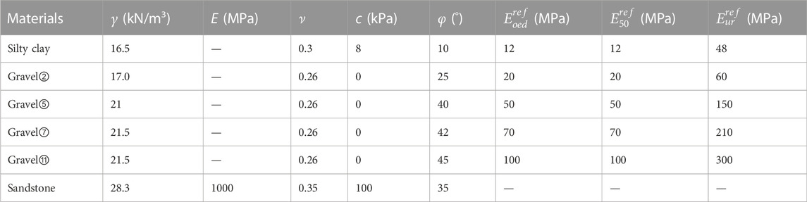
TABLE 2. Mechanical properties of different soils.
The case study consists of two parts: the PBA method for the second and third underground levels of the subway station and the open-cut method for the first underground level of the subway station overlying the existing structure. The development of the sequence model consisted of 23 steps. Among these steps, the PBA method included pilot tunnel excavation, primary lining construction, column installation, tunnel arch construction, soil excavation, and station structure construction. Once the PBA method was developed, the model displacement was set to zero. Subsequently, the open-cut method was developed, and included grouting reinforcement, retaining pile installation, soil excavation, and strut installation.
Model Validation
The parameters of the model were calibrated to verify its accuracy and reasonableness. Figure 10 shows the measured and calculated horizontal displacement curve of NEP A2 when He was 12.2 m. As shown in Figure 10, the results of the finite element analyses appear to provide reasonable agreement with the inclinometer observations. The maximum calculated and measured horizontal displacements were 1.41 and 1.89 mm, respectively. Moreover, the location of the calculated and observed maximum values was at an approximate depth of 4 m below the ground surface. Based on these comparisons, the accuracy of the finite element model in predicting excavation behavior, such as the deformation of piles and the surrounding soils, was verified. Thus, the numerical model satisfies the requirements of this study.
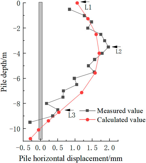
FIGURE 10. Comparison of the observed and calculated horizontal displacement curves of retaining pile A2.
Influence of connection joints of non-embedded piles
In the open-cut excavation process, parts of the deep excavation retaining pile wall will inevitably be constructed atop the existing structure, resulting in the piles in this area being end-suspended piles. For end-suspended piles, the connection treatment of the pile bottom is important to maintain the stability of the deep excavation. Therefore, the connection joint at the pile bottom was analyzed to determine the pile bottom connection treatment on the mechanical response of the retaining wall piles and the deformation of the existing structure. According to the results of the finite element model, four construction sequences, that is, excavation depths of 4, 8.7, and 12.2 m and the removal of the third level of steel struts, were analyzed.
Vertical deformation of the existing structure
Figures 11A,B show the uplifts at the bottom of the deep excavation along the transverse and longitudinal directions, respectively. As shown in Figure 11, during the construction of the deep excavation for the expansion above the existing structure, the base of the deep excavation was uplifted regardless of whether the pile bottom and existing structure were connected, and the amount of uplift was essentially identical. These findings are consistent with those of previous studies. The uplift at the bottom of the deep excavation was mainly caused by soil rebound owing to excavation-induced unloading (Guobin et al., 2000). The uplift of the deep excavation bottom was not dependent on the pile bottom connection to the existing structure.
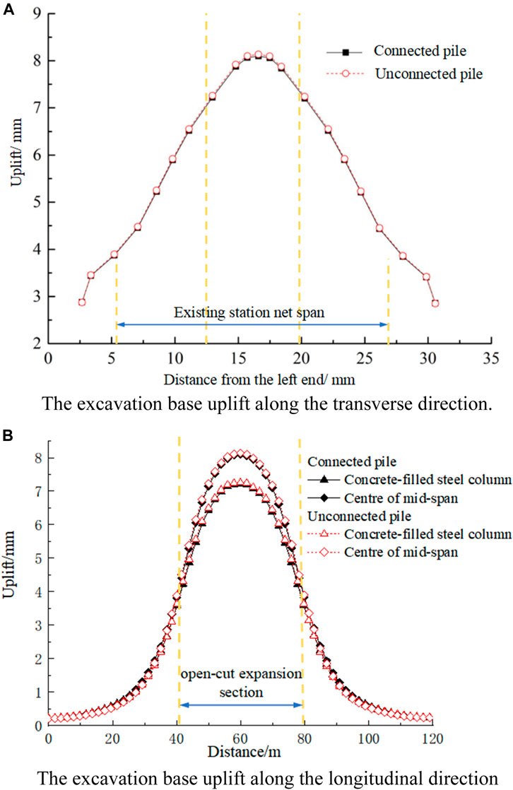
FIGURE 11. Comparison curves of the excavation base uplift. (a) The excavation base uplift along the transverse direction; (b) The excavation base uplift along the longitudinal direction.
Horizontal deformation of the retaining piles
Figure 12 shows the horizontal displacement curves of pile A3 at various stages of construction where the pile bottom was either connected to or unconnected to the existing station structure. As shown in Figure 12, for shallow excavation depths, the pile bottom connection to the existing structure barely affected the horizontal displacement of the pile. This is mainly because the soil in the passive zone behind the piles has a restraining effect (Zihang, 2002) that limits the horizontal displacement of the retaining piles. When He was 12.2 m, the horizontal displacement of the pile increased significantly, with a maximum displacement of approximately 1.89 mm occurring at the pile base. This is because the pile bottom was not connected to the existing structure, causing kick-out failure to occur around the second level of struts (Jun et al., 2008). Finally, when the third level of struts was removed, the horizontal displacement increment was greater when the pile bottom was unconnected to the existing structure. Compared with connected and unconnected cases, the maximum displacement difference was 2.02 mm. The maximum displacement of the piles without connection joints was approximately 2.7 times that of the piles with connection joints. After removing the third level of steel struts, the pile was no longer restrained below a depth of 4 m, causing an increase in the horizontal displacement of the pile. At this time, the maximum displacement of the pies without connection joints was approximately 2.82 mm, located at a depth of 8.7 m. Thus, the maximum displacement position moved upward.
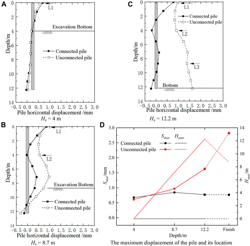
FIGURE 12. Comparison of the horizontal displacement curves of non-embedded pile A3. (a) He = 4 m; (b) He = 8.7 m; (c) He = 12.2 m; (d) The maximum displacement of the pile and its location.
Figure 12D shows the cures of the maximum displacement Smax of the pile and its location Hmax. The maximum displacement of connected pile Smax increased non-linearly with the increase of the excavation depth. For unconnected pile, the maximum displacement of the pile was almost unchanged and the maximum displacement occurred at the pile head.
Mechanical behaviors of the retaining piles
Figure 13 shows the bending moment variations of pile A3 at various stages of construction when connected and unconnected to the existing structure. Figure 13 demonstrates that at all four stages of construction, the bending moment curves of the connected and unconnected piles were similar. When the non-embedded pile bottom was unconnected to the existing structure, the bending moment at the pile bottom was zero. In this case, the rotation of the pile base was not constrained; therefore, the positive and negative bending moments of the pile without connection joints were smaller than those of the piles with connection joints. For the cases of He = 8.7 m, He = 12.2 m, and after the third level of struts was removed, the maximum bending moments of the unconnected pile were 57.1%, 56.9%, and 78.9% of the connected pile, respectively, thereby indicating a significant reduction in the bending moments.
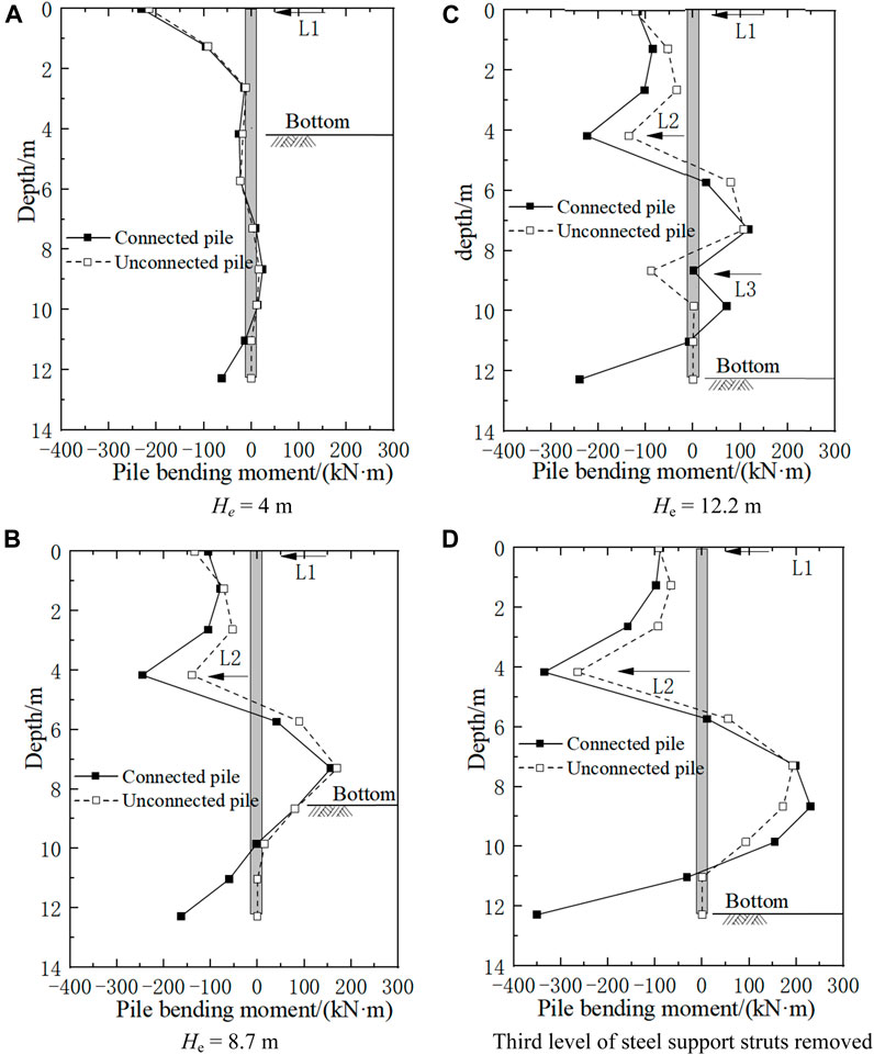
FIGURE 13. Comparison between the bending moments of non-embedded pile A3. (a) He = 4 m; (b) He = 8.7 m; (c) He = 12.2 m; (d) Third level of steel support struts removed.
Figure 14 shows the shear force curves of pile A3 when connected and unconnected to the existing structure at different construction stages. As shown in Figure 14, at all four stages of construction, the shear force curves of the connected and unconnected piles were similar. As the excavation depth increased, the shear force distribution was similar to that of a continuous beam, although a sudden change occurred at the strut position. Similar to the bending moment curve, when the pile was unconnected to the existing structure, the shear force was approximately zero within 3 m of the pile bottom.
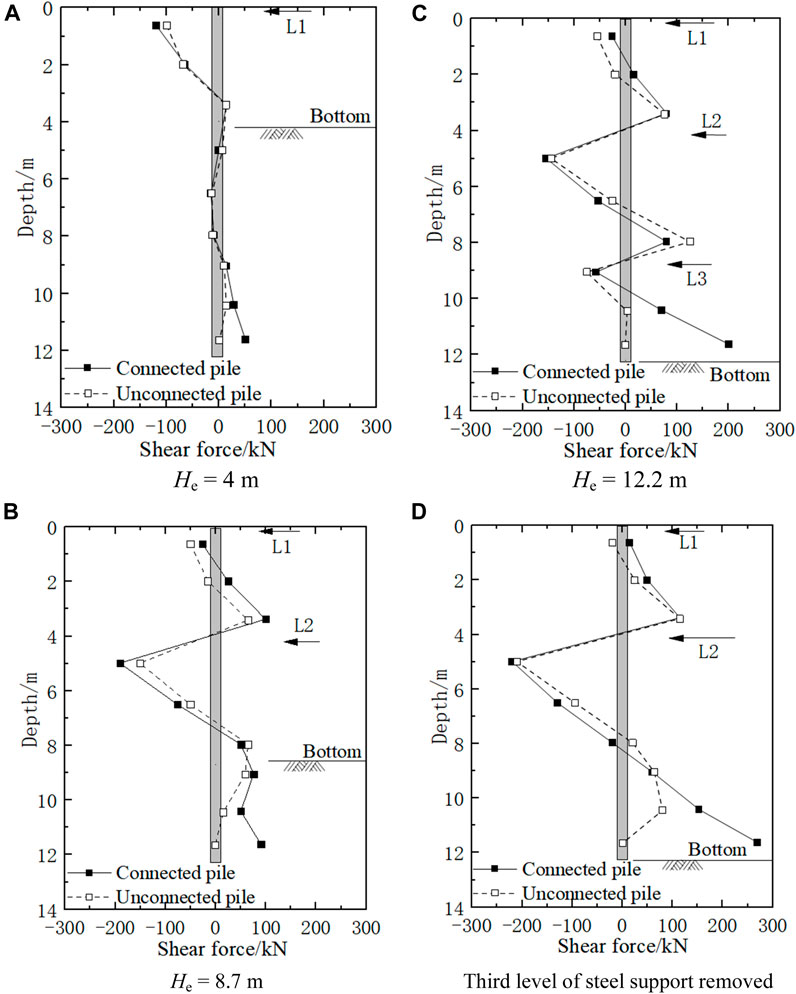
FIGURE 14. Shear force curves of non-embedded pile A3. (a) He = 4 m; (b) He = 8.7 m; (c) He = 12.2 m; (d) Third level of steel support struts removed.
According to the analysis, when the non-embedded pile was not connected to the existing structure, the displacement was greater and the stresses were smaller; the stress was approximately zero within 3 m of the pile base. The analysis shows that when a pile bottom is unconnected to the existing structure, the lateral earth pressure behind the pile is released through pile deformation, thereby decreasing the stress on the pile.
Parametric analysis of embedded piles
Considering that the EPs in the deep excavation of the expansion are adjacent to the existing station, their stress characteristics differ from those of a conventional deep excavation. In this case study, the clearance between the EPs and the pilot tunnel of the existing station is only 0.2 m. Therefore, the retaining structure of the deep excavation and existing structure will affect each other significantly. In this section, the influence of the distance between the EPs and pilot tunnel wall is investigated using numerical analyses (see Figure 15). The distance between the EP B1 and the existing structure was defined as the pile proximity distance, LP. The stress and deformation of the deep excavation and retaining piles were analyzed by comparing the different Lp values. Based on the case history, the LP (center distance) values of 0.7, 2.7, 4.7, and 6.7 m were selected for this analysis.

FIGURE 15. Schematic of distance Lp between the EP and existing station.
Vertical deformation of the existing structure
Figure 16A shows the uplift at the bottom of the deep excavation with various LP values along the transverse direction. Because the excavation width varies for different LP values and to facilitate a comparison of the different curves, the center lines of the deep excavations for different cases are shown in Figure 16A. The yellow dashed lines indicate the positions of the sidewalls and centerline of the existing structure. Figure 16B shows the variation in the maximum uplift of the deep excavation bottom for various LP values. According to the different characteristics of the excavation uplift for different LP values, the uplift along the transverse direction was divided into two parts: the existing station structure and surrounding soils outside the structure.
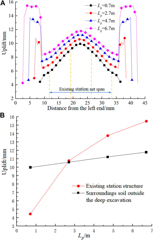
FIGURE 16. Comparison curves of the excavation base uplift. (a) Uplift at the excavation bottom along the transverse direction; (b) Schematic of distance Lp between the EP and existing station.
As shown in Figure 16A, for the existing station structure, the shape of the uplift curve did not change significantly with LP. As LP increased, the maximum uplift increased linearly (see Figure 16B). When LP was equal to 0.7 and 6.7 m, the maximum uplift values in the existing station structure were 9.80 and 11.80 mm, respectively, corresponding to an increase of approximately 20.4%, indicating that the maximum uplift increased by 0.33 mm for every 1 m increase of LP. For the surrounding soils outside the structure, the uplift values were large in the center and small at both ends of the curve. As LP increased, the maximum uplift increased non-linearly and gradually flattened. When LP was equal to 0.7 and 6.7 m, the maximum uplift values in the surrounding soils outside the structure were 4.40 and 15.50 mm, respectively, corresponding to a significant increase of 2.5 times. As LP increased, the restraining effect of the retaining wall piles and existing station structure on the uplift weakened, and thus, the uplift increased. Thus, the lower the LP value, the more stable the excavation bottom. Considering the limited space at the construction site, it is advisable to reduce the pile proximity distance LP to 0.2 m.
Horizontal deformation of retaining piles
Figure 17 shows the horizontal displacement of pile B1 for various Lp values. As shown in Figure 17, when the excavation depth is shallow, the influence of the Lp values on the horizontal displacement curve is insignificant. When He is 8.7 and 12.2 m and LP increases from 0.7 to 4.7 m, the maximum horizontal displacement of the pile increases by 0.37 and 0.82 mm, respectively, an increase of 21.8% and 39.4%, respectively. When Lp increases from 4.7 to 6.7 m, the horizontal displacement remains practically unchanged. According to the aforementioned analysis, as LP increases, the restraining effect of the existing station structure on the displacement of the EPs weakens, resulting in an increased displacement at the pile bottom. When LP increases to a certain distance, the restraining effect ceases. Therefore, the horizontal displacement of the pile tends to stabilize.
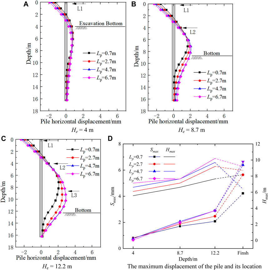
FIGURE 17. Horizontal displacements of EP B1 for various Lp values. (a) He = 4 m; (b) He = 8.7 m; (c) He = 12.2 m; (d) The maximum displacement of the pile and its location.
Figure 17D shows the cures of the maximum displacement Smax of the pile and its location Hmax. As shown in Figure 17D, the Smax values and Hmax values increased almost linearly with the increase of the excavation depth. The distance Lp could influence the location of the maximum displacement. The Hmax values increased with the increase of distance Lp.
Mechanical analysis of the retaining piles
Figure 18 shows the bending moment of pile B1 for various Lp values. As shown in Figure 18, the shape of the bending moment curve was barely affected by Lp. The effect of Lp on the bending moment was primarily observed at the bottom part of the pile. As LP increased, the negative bending moment decreased and the positive bending moment increased. Similar to the effect on horizontal displacement, the change in the bending moment was insignificant as Lp increased. A further increase in Lp beyond 4.7 m had practically no effect on the bending moment.
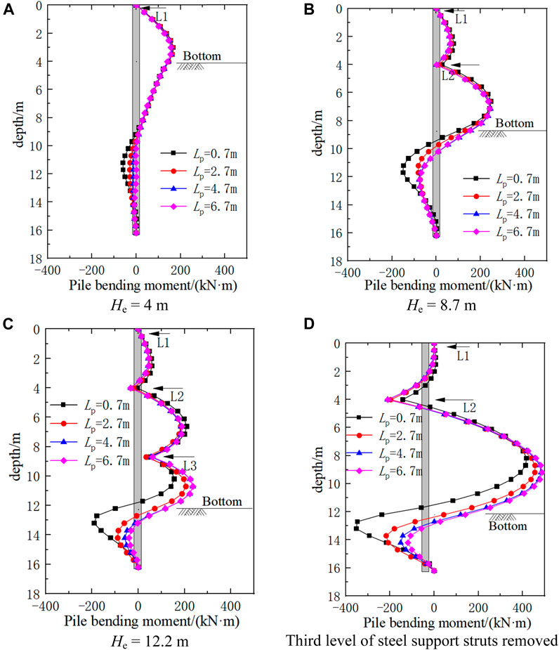
FIGURE 18. Bending moments of EP B1 for various Lp values. (a) He = 4 m; (b) He = 8.7 m; (c) He = 12.2 m; (d) Third level of steel support struts removed.
Based on this comprehensive analysis of the horizontal displacement and bending moment characteristics at various Lp values, as the Lp values of the embedded pile decreased, the restraint of the existing station structure on the pile increased, resulting in a decrease in the horizontal displacement of the pile and uplift of the deep excavation bottom. Therefore, we recommended that, considering the construction space, the Lp value be minimized to the maximum possible extent.
Effect of embedding depth of embedded piles
For the case study, the distance between the embedded piles and the wall of the existing station was set as 0.2 m. The embedment depth of the piles significantly affected the stability of the deep excavation. Thus, the embedment depth parameter HP was analyzed (see Figure 19). The effects of the embedment depth on the mechanical behaviors of the retaining piles were analyzed using FEM. The embedment depths used in the analysis were set as HP = 1, 2, 4, 6, and 8 m.
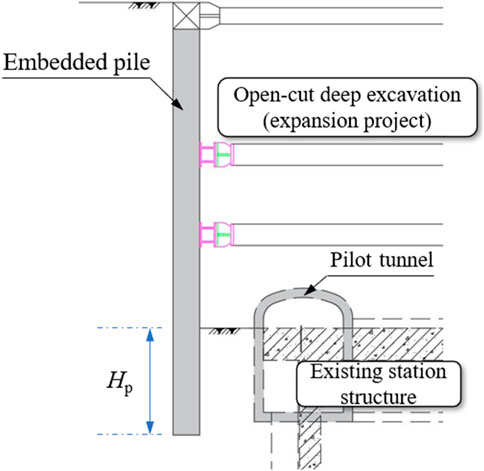
FIGURE 19. Location and embedment depth of the retaining piles and existing structure.
Horizontal deformation of retaining piles
Figure 20 shows the horizontal displacements of pile B1 for various HP values. As shown in Figure 20, at shallow excavation depths, the embedment depth had little effect on the horizontal displacement of the pile. For the case of the third level of struts of the deep excavation being removed, when Hp increased from 1 to 4 m, the maximum horizontal displacement of the pile decreased from 5.08 to 4.22 mm, corresponding to a decrease of approximately 16.9%. As Hp continued to increase beyond 4 m, the horizontal displacement remained practically unchanged. As Hp increased, the restraint of the existing station structure on the bottom of the embedded pile increased; therefore, the horizontal displacement at the pile bottom was limited. After Hp increased to a certain depth, the restraint of the existing structure ceased to increase, and the deformation of the pile tended to be constant.
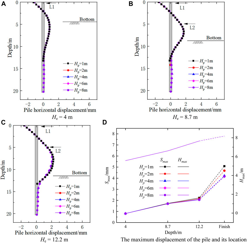
FIGURE 20. Horizontal displacement curves of EP B1 for various embedment depths. (a) He = 4 m; (b) He = 8.7 m; (c) He = 12.2 m; (d) The maximum displacement of the pile and its location.
Figure 20D shows the cures of the maximum displacement Smax of the pile and its location Hmax. As shown in Figure 20D, the Smax values and Hmax values increased with the increase of the excavation depth. The embedment depth of the pile Hp has little influence on the Smax and Hmax.
Mechanical behaviors of the retaining piles
Figure 21 shows the bending moments of the embedded piles with various Hp. values. As shown in Figure 21, the embedment depth had no effect on the bending moment of the embedded pile. When the excavation depth was shallow, the Hp barely affected the bending moment. When the third level of struts was removed, Hp primarily affected the bending moment at the bottom of the pile. When Hp increased from 1 to 4 m, the positive bending moment of the pile decreased, and the negative bending moment increased. After Hp exceeded 4 m, the bending moment remained constant, and the bending moment of the pile below a Hp of 5 m was negligible.
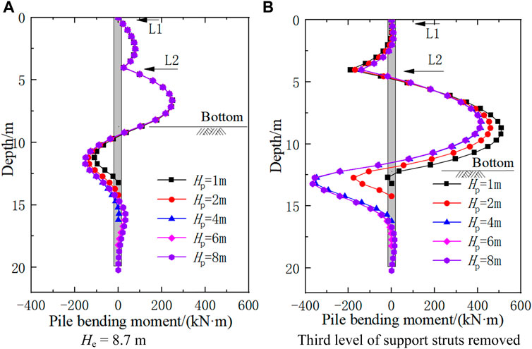
FIGURE 21. Bending moments of EP B1 for various embedment depths. (a) He = 4 m; (b) He = 8.7 m; (c) He = 12.2 m; (d) Third level of steel support struts removed.
Based on this parametric analysis of the embedment depth, the findings indicate that as the embedding depth increases, the horizontal displacement of the pile decreases and the bending moment increases, which is conducive to the stability of the deep excavation. When the embedding depth exceeds a certain value (Hp > 4 m), the horizontal displacement and stress of the pile remain practically constant. Therefore, the optimal embedment depth for similar project is 4 m.
Conclusion
In this study, the case history of the Pingguoyuan subway station expansion project of Beijing Subway Line 1 was investigated. A series of numerical investigations were conducted to simulate the dynamic construction process of deep excavations overlying existing structures. The complex interactions between the retaining structures of the deep excavation and existing subway structures were analyzed. This lays a theoretical and technical foundation for optimizing the design method and construction measures for complex expansion project and innovating engineering applications. The following conclusions are drawn:
1) Regardless of whether or not the non-embedded piles were connected to the existing structure, the shape and magnitude of the uplift curve of the deep excavation bottom were negligibly affected. However, when the embedded piles were unconnected, the horizontal displacement significantly increased at different construction stages, with the maximum displacement increasing by approximately 2.7 times that of the connected piles. Meanwhile, the maximum displacement position moving upward. Thus, the connection treatment of the pile base and grouting reinforcement behind the pile had a good reinforcement effect.
2) When a non-embedded pile was unconnected to the existing structure, the bending moment and shear force of the pile were reduced by varying degrees at all construction stages. In particular, the bending moment and shear force within 3 m of the pile bottom base were approximately zero. The bending moment of the pile was significantly reduced compared to that of the unconnected pile. The maximum bending moments of the unconnected pile are approximately 56.9%–78.9% of that of the connected pile. These findings indicate that the deformation of the unconnected pile releases the earth pressure behind the pile, which is not conducive to the stability of the deep excavation.
3) As the proximity distance LP of the embedded pile increased, the maximum uplift in the existing station structure part increases linearly. When Lp was 6.7 m, the uplift increased by approximately 20.4% compared to the case when Lp was 0.7 m. The maximum uplift in the surrounding soil increased non-linearly. When Lp was 6.7 m, the uplift increased to 2.5 times from when Lp was 0.7 m. Therefore, when permitted by construction site conditions, the pile proximity distance LP should be minimized.
4) When LP was 4.7 m, the maximum horizontal displacement of the pile increased by 39.4% compared to the case when LP was 0.7 m. In this case, the negative bending moment decreased, and the positive bending moment increased. After LP exceeds 4.7 m, the displacement and bending moment of the pile tended to change slowly, indicating that the greater the Lp value, the weaker the restraint of the existing structure on the pile. Meanwhile, the restraint of the existing structure can be neglected when LP exceeds a certain distance.
5) According to the mechanical behavior analysis of the embedded pile influenced by the embedment depth Hp, the bottom of the pile was primarily affected. When Hp increased from 1 to 4 m, the maximum horizontal displacement of the pile decreased by 16.9%. After Hp exceeded 4 m, the deformation of the pile remained essentially unchanged. Therefore, an embedding depth of 4 m is recommended for similar projects.
Data availability statement
The original contributions presented in the study are included in the article/Supplementary Material, further inquiries can be directed to the corresponding authors.
Author contributions
JH: Conceptualization, methodology, software, writing—original draft. JW: Writing—review and editing, data curation. CC: Investigation, writing—review and editing, resource. CZ: Investigation. EL: Data curation. ZW: Language editing. JS: Writing—review and editing. JL: Investigation.
Funding
This work was supported by the Doctoral Research Fund of Shandong Jianzhu University (Grant No. X19080Z) and China Railway Construction Corporation Limited’s 2020 annual scientific research plan (Grant No. 2020-B05). We deeply appreciate for the warm and efficient work by editors and reviewers.
Conflict of interest
Author EL and ZW was employed by the company China Railway 14th Bureau Group Co, Ltd.
The remaining authors declare that the research was conducted in the absence of any commercial or financial relationships that could be construed as a potential conflict of interest.
Publisher’s note
All claims expressed in this article are solely those of the authors and do not necessarily represent those of their affiliated organizations, or those of the publisher, the editors and the reviewers. Any product that may be evaluated in this article, or claim that may be made by its manufacturer, is not guaranteed or endorsed by the publisher.
References
Caide, W., Jie, Z., and Yichong, C. (2017). Effect analysis of displacement control measures for deep foundation pit adjacent to subway station. Urban Mass Transit 20 (05), 117–121. doi:10.16037/j.1007-869x.2017.05.026
Chen, Z., Zhou, H., Ye, F., Fu, W., and Liu, B. (2021). The characteristics, induced factors, and formation mechanism of the 2018 Baige landslide in Jinsha River, Southwest China. CATENA 203, 105337. doi:10.1016/j.catena.2021.105337
Clough, G. W., and O'Rourke, T. D. (1990). Construction induced movements of in situ wall. Atlanta, United StatesGeotechnical Special Publication, 439–470.
Cui, J., and Nelson, J. (2019). Underground transport: An overview. Tunn. Undergr. Space Technol. 87, 122–126. doi:10.1016/j.tust.2019.01.003
Cui, S., Pei, X., Jiang, Y., Wang, G., Fan, X., Yang, Q., et al. (2021). Liquefaction within a bedding fault: Understanding the initiation and movement of the Daguangbao landslide triggered by the 2008 Wenchuan Earthquake (Ms = 8.0). Eng. Geol. 295, 106455. doi:10.1016/j.enggeo.2021.106455
Gang, Z., Tao, Z., and Xuesong, C. (2017). Effect of foundation piles on excavation stability and its calculation. Chin. J. Geotechnical Eng. 39 (S2), 5–8. doi:10.11779/CJGE2017S2002
Guobin, L., Yuanxiong, H., and Xueyuan, H. (2000). A practical method ror calculating a heave of excavated foundation. China Civ. Eng. J. 33 (04), 61–67. doi:10.15951/j.tmgcxb.2000.04.013
Han, J., Zhao, W., Chen, Y., Jia, P., and Guan, Y. (2017). Design analysis and observed performance of a Tieback anchored pile wall in sand. Math. Problems Eng. 2017, 1–23. doi:10.1155/2017/8524078
Han, J., Zhao, W., and Li, T. (2020). Field measurement and numerical analysis of the influences between the deep excavation and adjacent buildings. Adv. Eng. Sci. 52 (04), 149–156. doi:10.15961/j.jsuese.201901052
Huang, M., Ninić, J., and Zhang, Q. (2021). BIM, machine learning and computer vision techniques in underground construction: Current status and future perspectives. Tunn. Undergr. Space Technol. 108, 103677. doi:10.1016/j.tust.2020.103677
Jun, Z., Zhixin, C., and Yuming, M. (2008). Study of built-in depth of anchored piles against landslide. J. Northeast. Univ. Sci. 11, 1637–1640+1651.
Kang, C., Riqing, X., and Hongwen, Y. (2020). Simplified method for evaluating deformation responses of existing tunnels due to overlying basement excava. Chin. J. Geotechnical Eng. 39 (03), 637–648. doi:10.13722/j.cnki.jrme.2019.1074
Khoiri, M., Ou, C. Y., and Teng, F. C. (2014). A comprehensive evaluation of strength and modulus parameters of a gravelly cobble deposit for deep excavation analysis. Eng. Geol. 174 (8), 61–72. doi:10.1016/j.enggeo.2014.03.008
Li, H., He, Y., Xu, Q., Deng, j., Li, W., and Wei, Y. (2022). Detection and segmentation of loess landslides via satellite images: A two-phase framework. Landslides 19, 673–686. doi:10.1007/s10346-021-01789-0
Liu, N., Wan, Y., Cao, C., and Liu, X. (2022). Innovative solutions for layout planning and implementation of a metro station and its accessory structures in mountainous cities, China. Tunn. Undergr. Space Technol. 1298, 104670. doi:10.1016/j.tust.2022.104670
Masini, L., Gaudio, D., Rampello, S., and Romani, E. (2021). Observed performance of a deep excavation in the historical center of Rome. J. Geotechnical Geoenvironmental Eng. 147 (2), 05020015. doi:10.1061/(asce)gt.1943-5606.0002465
Peck, R. B. (1969). “Deep excavations and tunneling in soft ground,” in 7th International Conference on Soil Mechanics and Foundation Engineering, Mexico, 1969.
Shuling, H., Xiating, F., and Chuanqing, Z. (2008). Study of method comprehensive evaluation for papameters of constitutive model of rock mass. Chin. J. Rock Mech. Eng. 27 (S1), 2624–2630.
Song, D., Chen, Z., Chao, H., Nie, W., and Ke, Y. (2020a). Numerical study on seismic response of a rock slope with discontinuities based on the time-frequency joint analysis method. Soil Dyn. Earthq. Eng. 133, 106112. doi:10.1016/j.soildyn.2020.106112
Song, D., Chen, Z., Ke, Y., and Nie, W. (2020b). Seismic response analysis of a bedding rock slope based on the time-frequency joint analysis method: A case study from the middle reach of the jinsha river, China. Eng. Geol. 274, 105731. doi:10.1016/j.enggeo.2020.105731
Tan, Y., and Lu, Y. (2018). Responses of shallowly buried pipelines to adjacent deep excavations in Shanghai soft ground. J. Pipeline Syst. Eng. Pract. 9 (2), 05018002. doi:10.1061/(asce)ps.1949-1204.0000310
Wang, J., Han, J., Chen, J., Ding, G., Feng, G., Liu, T., et al. (2022). Experimental and numerical study on the dynamic response of a superthick backfill subgrade under high-speed Railway loading: A case study of qianjiang–zhangjiajie–changde railway. J. Constr. Eng. Manag. 148. doi:10.1061/(ASCE)CO.1943-7862.0002407
Xiaogang, W. (2016). The deformation law of retaining structure and soil of deep foundation pit by suspending pile in metro. Sci. Technol. Eng. 16 (14), 280–287.
Xu, X., Li, Z., Fang, Q., and Zheng, H. (2020). Challenges and countermeasures for using pile-beam-arch approach to enlarge large-diameter shield tunnel to subway station. Tunn. Undergr. Space Technol. 98, 103326. doi:10.1016/j.tust.2020.103326
Yingren, Z., and Shangyi, Z. (2005). Limit state finite elemrnt method for grotechical engineering analys and its applications. China Civ. Eng. J. 38 (01), 91–98+104. doi:10.1360/biodiv.050084
Yong, W., and Jianyong, Y. (2005). Numerical simulation of horizontal brace system in bracing structure combined with underground structure. Chin. J. Undergr. Space Eng. 1 (04), 591–594.
Zelin, Z., Shougen, S., and Liang, C. (2015). Analysis of uplift deflection of subway tunnel due to adjacent pit excavation. Chin. J. Geotechnical Eng. 37 (12), 2224–2234. doi:10.11779/CJGE201512012
Zhao, W., Han, J. Y., Chen, Y., Jia, P. J., Li, S. G., Li, Y., et al. (2018). A numerical study on the influence of anchorage failure for a deep excavation retained by anchored pile walls. Adv. Mech. Eng. 10 (2), 168781401875677. doi:10.1177/1687814018756775
Zhou, J., Wei, J., Yang, T., Zhang, P., Liu, F., and Chen, J. (2021). Seepage channel development in the crown pillar: Insights from induced microseismicity. Int. J. Rock Mech. Min. Sci. 145, 104851. doi:10.1016/j.ijrmms.2021.104851
Keywords: subway station, extension excavation, mechanical behavior, numerical simulation, parametric analysis
Citation: Han J, Wang J, Cheng C, Zhang C, Liang E, Wang Z, Song J-J and Leem J (2023) Mechanical response and parametric analysis of a deep excavation structure overlying an existing subway station: A case study of the Beijing subway station expansion. Front. Earth Sci. 10:1079837. doi: 10.3389/feart.2022.1079837
Received: 25 October 2022; Accepted: 12 December 2022;
Published: 06 January 2023.
Edited by:
Zhuo Chen, Sichuan Agricultural University, ChinaReviewed by:
Fei Guo, China Three Gorges University, ChinaPengpeng Ni, Sun Yat-sen University, China
Copyright © 2023 Han, Wang, Cheng, Zhang, Liang, Wang, Song and Leem. This is an open-access article distributed under the terms of the Creative Commons Attribution License (CC BY). The use, distribution or reproduction in other forums is permitted, provided the original author(s) and the copyright owner(s) are credited and that the original publication in this journal is cited, in accordance with accepted academic practice. No use, distribution or reproduction is permitted which does not comply with these terms.
*Correspondence: Cheng Cheng, Y2hlbmdjaGVuZ25ldUAxNjMuY29t; Chaozhe Zhang, Y2hhb3poZV96aGFuZ0AxNjMuY29t