
95% of researchers rate our articles as excellent or good
Learn more about the work of our research integrity team to safeguard the quality of each article we publish.
Find out more
ORIGINAL RESEARCH article
Front. Earth Sci. , 17 January 2023
Sec. Geohazards and Georisks
Volume 10 - 2022 | https://doi.org/10.3389/feart.2022.1075928
This article is part of the Research Topic Spatial Modelling and Failure Analysis of Natural and Engineering Disasters through Data-based Methods - Volume II View all 36 articles
 Han Jiang1Xiaolong Fang1Ming Yu1Lin Li1
 Bing Han2Song Gao2Chengxian Zhai2Renxin Gao2Jianxiong Zhao2
 Liu Liu2*
Since there is no precedent for the use of slotted shield tunneling in the large section of high-speed railways in China, the relevant technological accumulation and systematic research achievements are few. Therefore, this paper provides theoretical support for loess tunnel construction decision-making through the study of slotted shields and is expected to promote the mechanization and even intelligent construction of a high-speed iron-loess tunnel. Taking the Luochuan tunnel of the Xiyan high-speed railway as the engineering background, this paper uses the numerical simulation software packages of ANSYS and FLAC3D to study the tunnel deformation (surface settlement, vault settlement, tunnel bottom uplift, and horizontal convergence) caused by the slotted shield construction in three different buried depths of 30, 40, and 50 m surrounding rock. The deformation law and mechanical characteristics of a cutter shield construction of large cross-section loess tunnels under the influence of different buried depths are put forward. Results showed that 1) the mutual interference between the working procedures can be significantly reduced by inserting the cutting tool into the soil instead of the advanced tubule before excavation; 2) the settlement in the upper part of the longitudinal axis of the tunnel is the largest; the greater the depth of the tunnel is, the smaller the surface settlement is; and 3) the horizontal deformation of the arch waist and foot of the tunnel under different buried depths is symmetrically distributed into the tunnel during the whole process of slotted shield tunneling.
At present, the number and mileage of tunnels are increasing with the continuous growth of the mileage of high-speed railways in China. The construction method, construction technology, and construction machinery of high-speed railway tunnels have made great progress, for example, the opening of the Yinxi high-speed railway, Baolan high-speed railway, and Zhengxi high-speed railway has accumulated valuable experience for the construction of the loess tunnel of high-speed railways in our country. However, due to the large cross-section of high-speed railways and the particularity of the loess stratum, the loess tunnels built at the present stage are constructed using traditional mining methods (Birk et al., 2010; Xue et al., 2018; Zhang et al., 2018; Wang et al., 2019). So far, there is no precedent for the construction of slotted shields in a loess tunnel. There is no systematic research on the application of a shield method in high-speed railway tunnels, and there is little experience that can be used for reference (Jiang et al., 2017; Yang, et al., 2020; Niu et al., 2021; Weng et al., 2021; Zhu, 2021; Mei et al., 2022).
Compared with the common loess tunnel construction methods such as the three-step method and CRD method, the slotted shield method can make full use of the advantages of the shield method and mining method (Liang et al., 2016; Wang et al., 2019; Zhou et al., 2020; Hong et al., 2021; Xu et al., 2021; An et al., 2022). In other words, before excavation, the cutters were inserted into the soil instead of the advanced small pipe for pre-support, and the follow-up excavation and support work were carried out under the protection of the shield shell, which can significantly reduce the mutual interference between the various processes. The slotted shield is suitable for strata with low water contents and certain self-stabilization, and the strata with a stable palm surface can be maintained by dewatering or grouting (Wu et al., 2014; Min et al., 2015; Song et al., 2019; Dai et al., 2020). After the effective demonstration, the slotted shield construction is more suitable for the long loess tunnels in the Xiyan high-speed railway, the Xikang high-speed railway, and the Xishi high-speed railway.
At present, research on slotted shield construction of loess tunnels is relatively few. Some scholars and experts have discussed the large-scale mechanized construction of loess tunnels and the construction idea, application prospect, and working principle of the slotted shield. Sun (2017) took the pre-slotting construction of the Hongliangying large cross-section loess tunnel as the background to study the mechanized construction of the weak surrounding rock. The support parameters of pre-lining are analyzed by numerical simulation methods to provide reference for the design and construction of similar projects. Wang and Guo (2020) explained that based on the background of the Xiyan high-speed railway project, the construction technology of the shield and mining method is integrated according to the engineering characteristics of a loess tunnel, and the idea of slotted shield construction is put forward. The Informa ionization of mechanized construction of loess tunnels is explored based on 5G to promote the development of intelligent construction technology of loess tunnels. Bai (1996)stated that by introducing the structure and working principle of the half-section cutter shield, this paper discusses its application prospect in underground engineering construction. Guo and Deng (1997) explained that through the field measurement, it is proven that the half-section cutter that inserts the shield has good technical performance and high economic benefit, so it is worth popularizing and using on a large-scale mechanized construction. Deng and Yang (1997) stated that by analyzing the slotted shield scheme of an expressway tunnel, the characteristics and working principle of each component of the slotted shield are introduced in detail.
In this paper, based on the background of the Luochuan tunnel of the Xiyan high-speed railway, the construction deformation of a large cross-section loess tunnel with a slotted shield under different buried depths is analyzed and discussed by using the numerical simulation method. It is expected to provide a reference basis for the mechanized and intelligent construction of high-speed railway tunnels in the later stage.
The Luochuan tunnel of the Xiyan high-speed railway (Xi’an to Yan’an) was originally designed for slotted shield construction. The tunnel is located in Houston Township, Luochuan County, Yan’an city, Shaanxi Province, with a total length of 4140.43 m (mileage DK194 + 759.57 ∼ DK198 + 900). It is a single-hole double-track large cross-section loess tunnel. The tunnel passes through the loess beam plateau. The topography of beam tablelands is flat, and the gully around the plateau is well developed. The entrance of the tunnel is located on a loess beam slope with a gentle slope of about 30°. The slope is densely covered with shrubs, and there is water in the gully below it. The exit is located on the loess plateau with dense vegetation, especially apple trees. The loess beam above the tunnel is complete, and gullies are developed on both sides. The whole tunnel is shallowly buried with a depth of 80.64 m. The vertical and cross sections of the tunnel are shown in Figures 1, 2.
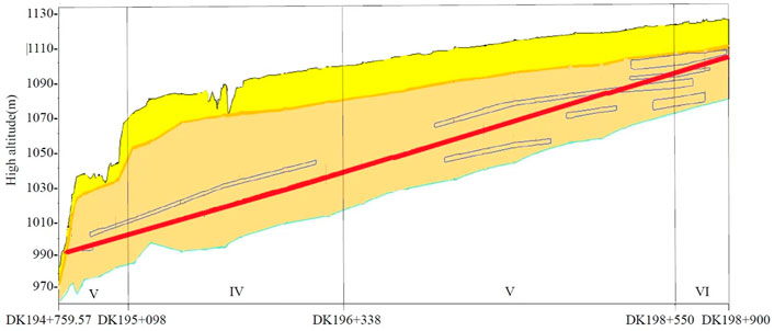
FIGURE 1. Profile of the Luochuan tunnel.
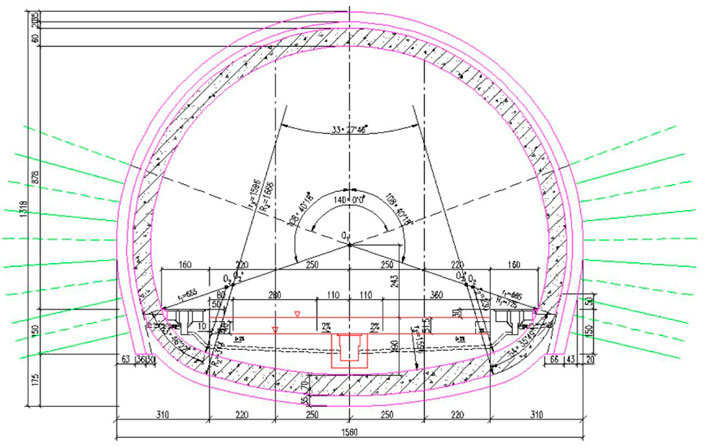
FIGURE 2. Tunnel lining section.
The tunnel passes mainly through the Neocene and Middle Pleistocene aeolian strata, and the sequence from the top to bottom is as follows: Quaternary Upper Pleistocene clayey loess (Q3eol), Quaternary Upper Pleistocene paleosol (Q3el), Quaternary Middle Pleistocene clayey loess (Q2eol), and Quaternary Middle Pleistocene paleosol (Q2el). The main physical and mechanical parameters of each stratum are shown in Table 1.
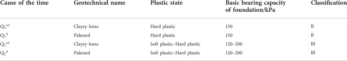
TABLE 1. Mechanical parameters of the ground soil.
The plug-in shield is mainly composed of the main engine, the rear matching trolley, and the lining matching trolley, and its schematic diagram is shown in Figure 3. The main engine is mainly composed of the cutter, racks, retaining plates, propulsion cylinders, connecting tail plates, buckets, and scrapers; rear supporting equipment is used for shotcreting, bolting, and installing a steel arch frame for initial support; the lining matching trolley is used for laying the waterproof board and secondary lining. The length of the slotted shield machine studied in this paper is 7.2 m, the length of the notch (the distance between the upper cutter and the bottom cutter) is 1 m, and the shape of the notch is oblique bearing. The thickness of the shield shell is 0.2 m, the propulsion stroke of the cylinder is 0.6 m, and the excavation footage is 0.6 m. The excavation is divided into the upper and lower steps, in which the height of the upper and lower steps is 7.6 and 5.4 m, respectively. The excavation is divided into the upper and lower steps, in which the height of the upper and lower steps is 7.6 and 5.4 m, respectively.
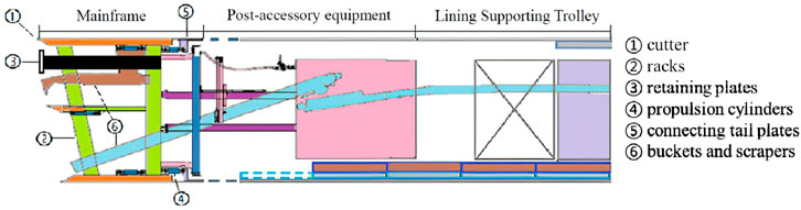
FIGURE 3. Structure of a slotted shield.
The shield machine pushes out all the cutters to pre-support the soil to be excavated in front to prevent the excavation face from collapsing. First of all, the circumferential excavation of the arch soil is carried out, and a retaining block should be dug where there is a retaining plate. When the upper step soil is excavated 0.6 m forward, all the insert cutter oil cylinders are recovered, and the frame is pulled back to the initial state; then, the lower step soil is excavated. The aforementioned steps are repeated. When the shield tail clearance is 0.6 m, the spray mixing bridge device sets up side wall anchors, erects section steel frames, and hangs nets to spray concrete to the design thickness. After the initial support reaches the design strength, the lining trolley is used to lay the water discharge board and secondary lining. In other words, the construction procedure of a cutter shield is as follows: construction preparation—introduction of all cutters—excavation up steps—frame follow-up, introduction of all cutters—excavation down steps—after supporting equipment for initial support—lining supporting the trolley laying waterproof board, and pouring secondary lining (Jiang et al., 2018; Chang et al., 2020; Huang et al., 2020; Huang et al., 2020; Huang et al., 2020).
The slotted shield method is used in a loess tunnel for the first time. To effectively verify the deformation law of the tunnel surrounding rock during the construction of a cutter shield, ANSYS combined with FLAC3D finite element software is adopted in this paper and was used to realize tunnel model building and grid division, and FLAC3D was used to complete calculation and post-processing. After establishing the numerical model of cutter shield construction, the construction deformation law is studied under the condition of different burying depths (30, 40, and 50 m).
(1) The soil is assumed to be homogeneous, continuous, and isotropic, and the calculation model is an elastic–plastic constitutive model.
(2) The soil parameters in the model are selected according to the geological survey report and relevant specifications.
(3) The initial stress field only considered the gravity stress field, ignoring the influence of the surrounding rock tectonic stress field and groundwater.
(4) The shield shell is a thin shell structure of an isotropic linear elastic material.
The surrounding rock section of class V of the Xiyan Luochuan tunnel is 2531 m long, accounting for 61.1% of the total length of the tunnel. Therefore, this paper takes the surrounding rock of grade Ⅴa as the research background. According to the tunnel geological survey report and reference (Enterprise standard of China Railway Corporation, 2014; Profession Standard of The People’s Republic of China, 2016), the calculation model parameters and unit types of the grade Va surrounding rock are shown in Table 2.
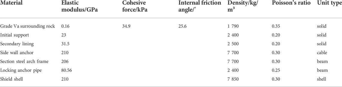
TABLE 2. Model parameters for the grade Va surrounding rock.
The left and right sides of the model are X-direction constraints, the front and rear are Y-direction constraints, and the bottom of the model is Z-direction constraints. According to Saint-Venant’s principle, excavation only causes stress redistribution in a certain range around the tunnel. To reduce the influence of the boundary effect, the calculated boundary on the left and right sides of the tunnel is 3–5 times the total span of the tunnel, and the calculated boundary at the bottom of the tunnel is more than two times the total height of the tunnel, and the upper boundary of the tunnel is the free surface of the upper surface. When the buried depth is 30 m, the size of the tunnel model is 150 m × 120 m × 50 m, and the total number of units is 76,800; when the buried depth is 40 m, the size of the tunnel model is 150 m × 120 m × 60 m, and the total number of units is 76,800; when the buried depth is 50 m, the size of the tunnel model is 150 m × 120 m × 70 m, and the total number of units is 85,200. Under the condition of different buried depths, the size of the model and its elements are given in Table 3.
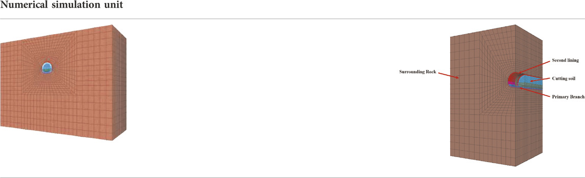
TABLE 3. FEM model meshing.
Considering the influence of boundary conditions on the calculation results, the monitoring measurement is carried out at the longitudinal intermediate section of the tunnel. After the completion of the construction simulation, the displacement data on the measuring points are extracted, and the deformation analysis is carried out. The arrangement of the measuring points in the monitoring section is shown in Figure 4.
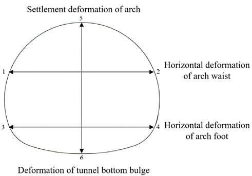
FIGURE 4. Layout of measuring points in the monitoring section.
Assuming that the cutters are all pushed out and the propulsion stroke is 0.6 m, this construction flowchart is shown in Figure 5.
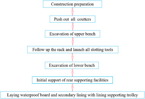
FIGURE 5. Construction sequence diagram of a slotted shield.
The construction process is simulated by ANSYS engineering simulation software, which is as follows.
After the displacement and speed are cleared, the cutter is pushed forward one stroke to activate the external imported (0 mm–0.6 m) shell unit. The cutter is pushed forward one more stroke, the external import (0 mm–1.2 m) shell unit is activated, and the previous shell unit is assigned to be empty. At the same time, the upper bench soil is excavated, and the footage is 0.6 m. Then, the supporting equipment would be used for initial support and that of the supporting trolley for lining was for waterproof boards and secondary lining.
After the excavation of the upper step is completed, the cutter is pushed forward one more stroke, the external import (0 m–1.8 m) shell unit is activated, and the previous shell unit is assigned to be empty. Then, the excavation of the lower steps is carried out while continuing to dig up the steps.
When the active external shell unit is 0–7.2 m, the shield mainframe will enter the soil to be excavated after several cycles. The initial support will be carried out immediately when the cutter is to be pushed forward for one stroke and there is a 0.6 m gap at the end of the shield. After introducing the cable element of a side wall anchor, the beam element of the section steel frame, and the beam element of locking the anchor pipe, the solid element is used to simulate the shotcrete process until the end of the shield construction. The schematic diagram of the cutter shield construction is given in Figure 6.
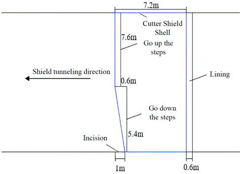
FIGURE 6. Sketch map of slotted shield tunneling.
For slotted shield construction, the surface subsidence, vault subsidence, tunnel bottom uplift, and horizontal convergence of the grade Va surrounding rock when the buried depth is 30 m, 40 m, and 50 m are studied. The surrounding rock deformation law of a slotted shield tunnel under different buried depths is studied.
From the curve of the land subsidence trough (Figure 7), it can be seen that the shape of the land subsidence trough with different buried depths is basically similar, and its influence range increases with the increase in the tunnel depth. The maximum surface subsidence occurs in the upper part of the longitudinal axis of the tunnel. Therefore, when the depth of the tunnel is 30 m, 40 m, and 50 m, the maximum surface settlement is –18.74 mm, −16.49 mm, and −13.76 mm, respectively. These data show that with the increase in the tunnel depth, the influence of soil loss on the surface decreases with the increase in the tunnel depth. In other words, the larger the buried depth of the tunnel is, the smaller the surface subsidence deformation is (Hu, 2011; Yang et al., 2015; Cao et al., 2018).
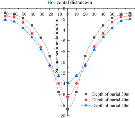
FIGURE 7. Ground surface settlement trough curves in different tunnel buried depths.
The vertical displacement cloud map of the surrounding rock of the tunnel under different buried depths is shown in Figure 8. According to the cloud map of vertical displacement of the surrounding rock, the distribution law of vertical displacement of the surrounding rock is similar with different burial depths.
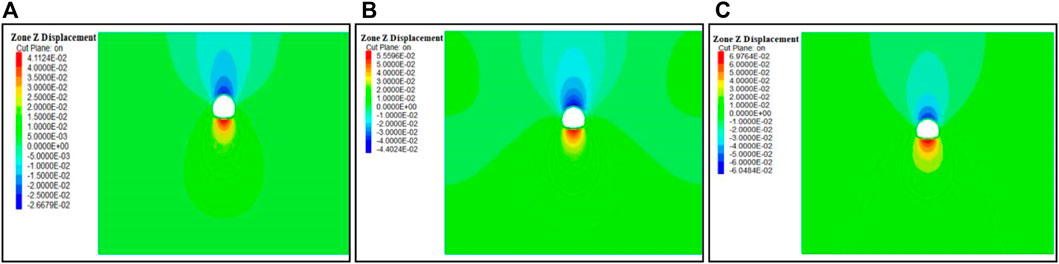
FIGURE 8. Vertical displacement cloud map of different buried depths. (A) Vertical displacement cloud map of 30 m buried depth; (B) vertical displacement cloud map of 40 m buried depth; and (C) vertical displacement cloud map of 50 m buried depth.
The deformation curves of a tunnel vault settlement and tunnel bottom uplift under different buried depths are given in Figures 9 and 10. As can be seen from the figure, with the approach of the excavation face, the subsidence at the vault of the study section and the uplift deformation at the bottom of the tunnel gradually increased. The deformation rate is also accelerated during the excavation of the cross-section because the insertion of the shield shell acts as a pre-support for the excavated soil; the settlement of the surrounding rock at the vault and the uplift deformation of the tunnel are restricted, and the deformation rate decreases significantly (Li and Zhu, 2013; Qi, et al., 2018; Zhou et al., 2018; Zhao et al., 2019; Zhang et al., 2020; Ge et al., 2022; Luo et al., 2022). After the excavation of the research section is completed, the excavation operation near the palm face has little effect on the settlement and deformation of the surrounding rock of the study section, which is due to the temporary support of the shield shell. As the shield tail leaves the research section, the supporting effect of the shield shell also disappears. At this time, the initial support should be carried out immediately (Li et al., 2017; Han, et al., 2018; Aydan and Hasanpour, 2019; Liu et al., 2019; Li et al., 2020; Mu et al., 2021). After the support reaches the design strength, the settlement of the surrounding rock and the deformation rate of the bottom uplift of the tunnel will be further reduced, and the final deformation tends to be stable.

FIGURE 9. Tunnel arch top settlement curve.
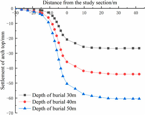
FIGURE 10. Tunnel bottom heaving curve.
The vault settlement and bottom uplift of the tunnel under different buried depths are shown in Table 4. With the increase of the burial depth, the settlement of vault and the uplift of tunnel bottom increased, and the deformation of uplift is larger than that of the vault. For example, when the buried depth is 30 m, the uplift at the bottom of the tunnel is 41.12 mm, the settlement of the vault is –26.68 mm, and the uplift deformation is 54.1% more than the settlement of the vault. When the buried depth is 40 m, it is 20.8% more; when the buried depth is 50 m, it is 15.3% more. It can be inferred that the deformation of the two tends to be close with the increase in the buried depth of the tunnel.
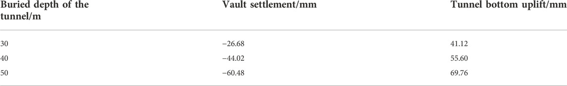
TABLE 4. Tunnel arch top settlement and bottom heaving.
Under different burial depths, the horizontal convergence displacement cloud map in the surrounding rock of the tunnel is shown in Figure 11. The distribution law of horizontal displacement of the surrounding rock is similar under the condition of different burial depths, according to the cloud map of horizontal displacement of the surrounding rock.
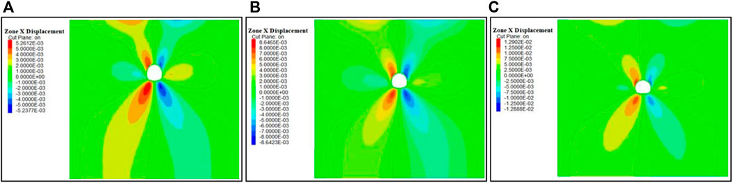
FIGURE 11. Horizontal displacement cloud map of different depths. (A) Horizontal displacement cloud map of 30 m buried depth; (B) horizontal displacement cloud map of 40 m buried depth; and (C) horizontal displacement cloud map of 50 m buried depth.
The horizontal displacement at the left and right arch waist of the tunnel and the horizontal displacement at the left and right arch feet are shown in Figures 12, 13. Under different burial depths, the horizontal deformation of the surrounding rock at the arch waist and foot presents a convergent deformation to the tunnel during the whole excavation process. The horizontal deformation and deformation rate of the surrounding rock at the arch waist and arch foot increased sharply with the vicinity of the excavation face. During the excavation of the cross section, the horizontal deformation of the surrounding rock at the arch waist and foot is constrained, and the decrease of the horizontal deformation rate of the surrounding rock is due to the pre-supporting effect of the insertion of the shield shell on the excavated soil (Ye et al., 2017; Zhou, et al., 2019; Fang et al., 2021; Tang, et al., 2021). As the shield tail is far away from the research section, the support of the shield shell disappears, resulting in a sharp increase in the horizontal deformation of the surrounding rock (Liu et al., 2019; Wang et al., 2020; Cao et al., 2021). After the initial support reaches the design strength, the horizontal deformation rate of the surrounding rock at the arch waist and foot of the study section decreases and finally tends to be stable.
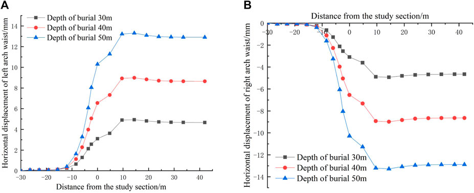
FIGURE 12. Horizontal displacement curve of an arch waist. (A) Horizontal displacement curve of the tunnel left arch waist; and (B) horizontal displacement curve of the tunnel right arch waist.
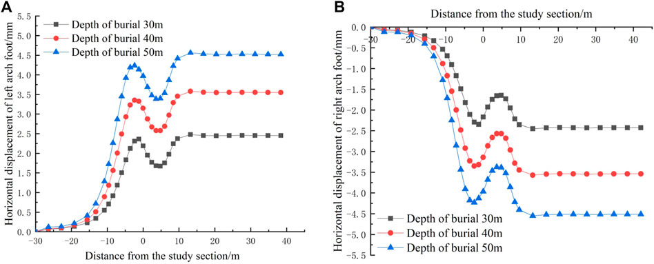
FIGURE 13. Horizontal displacement curve of an arch foot. (A) Horizontal displacement curve of the tunnel left arch foot; and (B) horizontal displacement curve of the tunnel right arch foot.
Under the condition of different buried depths, the horizontal displacement values of the left and right arch waist and arch foot of the tunnel are shown in Table 5. It can be seen from the table that the horizontal displacement around the cave shows a trend of uniform distribution on both sides. The number of deformations increases with the increase of buried depths. The horizontal deformation rate of the surrounding rock of the study section is accelerated with the proximity of the excavation face.

TABLE 5. Horizontal displacement values of the tunnel arch waist and foot.
After tunnel excavation, the stress field of the surrounding rock will be readjusted. Under the load, the surrounding rock will undergo a transition from elastic to plastic. When plastic deformation occurs in the surrounding rock, the surrounding rock will become loose, and the bearing capacity will decline, which will affect the stability of the tunnel, and even lead to tunnel instability. Therefore, attention should be paid to the analysis of plastic deformation of the surrounding rock. The cloud diagram is shown in Figure 14, and the analysis results are shown in Table 6.
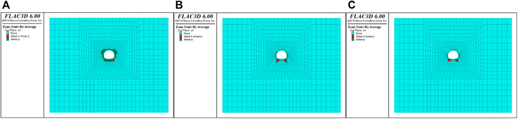
FIGURE 14. Distribution of the plastic zone for different burial depths. (A) Distribution of the plastic zone at a burial depth of 30 m; (B) distribution of the plastic zone at a burial depth of 40 m; and (C) distribution of the plastic zone at a burial depth of 50 m.
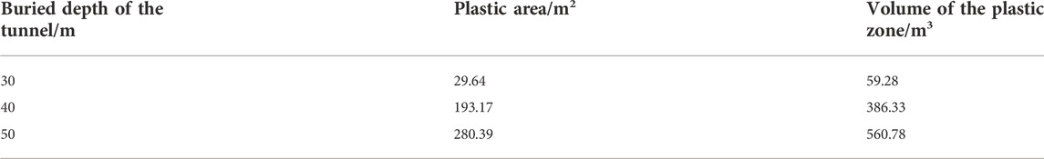
TABLE 6. Plastic area and volume at different burial depths.
It can be seen from Figure 14 that with the construction of the tunnel, the distribution trend of the surrounding rock plastic zone also gradually changes. Under different burial depths, the distribution of the surrounding rock plastic zone of the tunnel shows a symmetrical growth trend, the plastic zone at the arch shoulder and invert gradually decreases, and the plastic zone at the arch foot changes from a point to a sharp corner, with a maximum value.
When the buried depth of the tunnel increases from 30 m to 40m, the area and volume of the surrounding rock plastic zone increase from 29.64 m2 to 59.28 m3 to 193.17 m2 and 386.33 m3, respectively, with an increase rate of 84.7%. When the burial depth increases to 50 m, the area and volume of the surrounding rock plastic zone increase to 280.39 m2 and 560.78 m3, with an increase rate of 89.4%. It can be seen that the greater the burial depth of the surrounding rock, the more obvious the growth trend of the area and volume of the surrounding rock plastic zone of the tunnel, and the more likely it is to be damaged.
The maximum and minimum principal stress nephograms of shotcrete under different burial depths are extracted from the calculation results, as shown in Figure 15, and the analysis results are shown in Table 7.
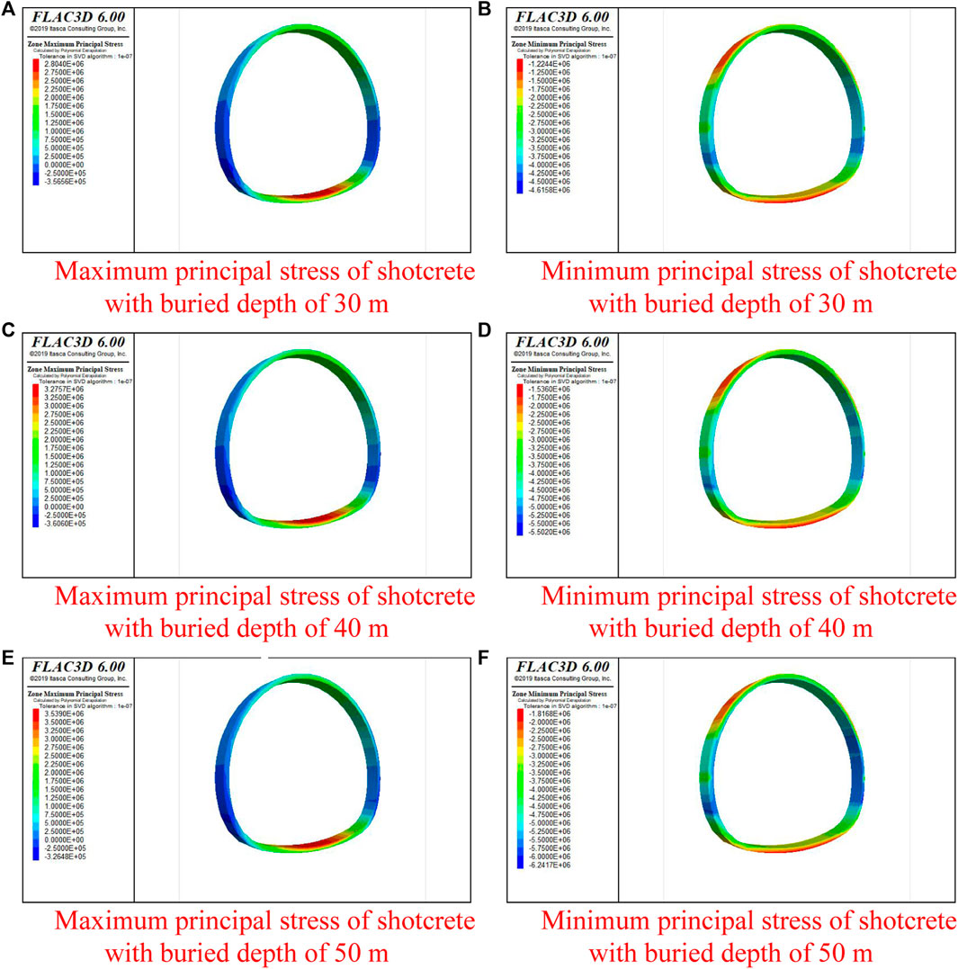
FIGURE 15. Cloud chart of maximum and minimum principal stresses of shotcrete at different burial depths. (A) Maximum principal stress of shotcrete with a burial depth of 30 m, and (B) minimum principal stress of shotcrete with a burial depth of 30 m. (C) Maximum principal stress of shotcrete with a burial depth of 40 m, and (D) minimum principal stress of shotcrete with a burial depth of 40 m. (E) Maximum principal stress of shotcrete with a burial depth of 50 m, and (F) minimum principal stress of shotcrete with a burial depth of 50 m.
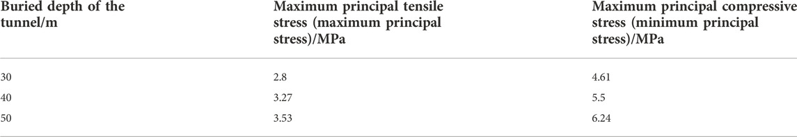
TABLE 7. Maximum and minimum principal stress of a research section with different burial depths.
It can be seen from Figure 15 that the minimum principal stress of shotcrete with a burial depth of 30 m is located at the arch foot, and its value is 4.61 MPa; the maximum principal stress is located at the arch foot, and its value is 2.8 MPa; the minimum principal stress of shotcrete with a burial depth of 40 m is located at the arch foot, and its value is 5.5 MPa; the maximum principal stress is located at the arch foot, and its value is 3.27 MPa; the minimum principal stress of shotcrete with a burial depth of 50 m is located at the arch waist and arch foot, and its value is 6.24 MPa; the maximum principal stress is located at the arch foot, and its value is 3.53 MPa.
Based on the results obtained from this study, we can draw the following conclusions:
(1) After the slotted shield inserts the cutter into the soil instead of the advanced small conduit for pre-support before excavation, the subsequent excavation and support work can be carried out under the protection of the shield shell, which can significantly reduce the mutual interference between the various processes. In the construction process, the maximum settlement occurs in the upper part of the longitudinal axis of the tunnel, and the greater the burial depth, the smaller is the surface settlement deformation.
(2) The vertical displacement distribution of the surrounding rock and the surrounding rock with different buried depths are similar. The greater the burial depths of the tunnel, the greater are the sinking of the vault and the uplift of the tunnel bottom. The uplift deformation at the bottom of the tunnel is always larger than that of the vault, but the deformation tends to be close with the increase of burial depths.
(3) The horizontal deformation of the arch waist and foot of the tunnel under different buried depths presents a symmetrical deformation to the tunnel in the whole slotted shield tunneling. Also, the greater the depth, the greater is the horizontal deformation around the tunnel.
(4) With the progress of tunnel excavation, the influence on the distribution of the surrounding rock plastic zone under different burial depths is distributed in a positive direction, and the maximum value appears in the plastic zone at the arch foot of the tunnel, so the construction risk at the arch foot is high, and the arch foot should be reinforced in time during the construction process. The maximum principal compressive stress value under different burial depths is less than the compressive strength of C25 concrete 12.5 MPa. Considering the interaction of a reinforcement mesh and steel frame, the initial tensile strength is greatly improved, so the tensile stress damage is not considered.
The original contributions presented in the study are included in the article/supplementary material; further inquiries can be directed to the corresponding author.
HJ: conceptualization, methodology, software, investigation, formal analysis, and writing—original draft; XF: data curation; MY: investigation; LnL: resources and supervision; BH: software; SG: validation; CZ: writing—review and editing; RG: supervision; JZ: writing—original draft; LuL: (corresponding author): conceptualization, funding acquisition, resources, supervision, and writing—review and editing.
This work was supported under grants from the Science and Technology Research and Development Plan of China Railway Corporation (Grant No: P2018G048). The authors declare that this study received funding from China Railway Corporation. The funder was not involved in the study design, collection, analysis, interpretation of data, the writing of this article, or the decision to submit it for publication.
The authors thank the China Railway 20 TH Bureau Group Co., Ltd., the Xiyan high-speed railway XYZQ-8 Bid of China Railway 20 TH Bureau Group Co., Ltd., and Shijiazhuang Tiedao University for technical assistance.
HJ, XF, MY, and LnL were employed by the 2nd Engineering Company and the 20th China Railway Bureau Group Co., Ltd.
The remaining authors declare that the research was conducted in the absence of any commercial or financial relationships that could be construed as a potential conflict of interest.
All claims expressed in this article are solely those of the authors and do not necessarily represent those of their affiliated organizations, or those of the publisher, the editors, and the reviewers. Any product that may be evaluated in this article, or claim that may be made by its manufacturer, is not guaranteed or endorsed by the publisher.
An, P., Chen, H., Sun, B. W., Xing, Y., Zhao, Q., Zhou, X., et al. (2022). A minimally invasive method for reinforcing the karez tunnel in Turpan based on the high mole ratio potassium silicate. Bull. Eng. Geol. Environ. 81 (4), 138. doi:10.1007/s10064-022-02633-y
Aydan, O., and Hasanpour, R. (2019). Estimation of ground pressures on a shielded TBM in tunneling through squeezing ground and its possibility of jamming. Bull. Eng. Geol. Environ. 78 (7), 5237–5251. doi:10.1007/s10064-019-01477-3
Bai, G. Y., 1996. Study of half section slotted shield and its application looking into the distance. The 9th annual meeting of tunnel and underground engineering society of civil engineering society of China. Beijing, 373–378.
Birk, T., Guldner, K., Mundt, K. A., Dahmann, D., Adams, R. C., and Parsons, W. (2010). Quantitative crystalline silica exposure assessment for a historical cohort epidemiologic study in the German porcelain industry. J. Occup. Environ. Hyg. 7 (9), 516–528. doi:10.1080/15459624.2010.487789
Cao, H. J., Liu, Z. Q., and Wu, J. (2018). Study on construction deformation law and reserved deformation of railway loess tunnel. Railw. Stand. Des. 62 (03), 85–89.
Cao, R. L., Peng, L. J., Zhao, Y. F., et al. (2021). Control of strata deformation in subway interval tunnels crossing a high-speed rail shield tunnel at a short distance. Arab. J. Sci. Eng. 46 (5), 5013–5022. doi:10.1007/s13369-020-05225-8
Chang, Z., Du, Z., Zhang, F., Huang, F., Chen, J., et al. (2020). Landslide susceptibility prediction based on remote sensing images and GIS: Comparisons of supervised and unsupervised machine learning models. Remote Sens. 12, 502. doi:10.3390/rs12030502
Dai, W., Xia, Y. M., Ning, B., and Yang, M. (2020). Numerical analysis of stress and temperature fields in a composite stratum based on a new method of shield construction for safety and environmental protection. Int. J. Environ. Res. Public Health 17 (2), 530. doi:10.3390/ijerph17020530
Deng, J. F., and Yang, S. Q. (1997). Slotted shield for soil tunnel construction. Road Mach. Constr. Mech. 06, 10–13.
Enterprise standard of China Railway Corporation (2014). Technical code for railway tunnel in loess (QCR9511-2014). Beijing: China Railway Press.
Fang, Q., Du, J. M., Li, J. Y., Zhang, D. l., and Cao, L. q. (2021). Settlement characteristics of large-diameter shield excavation below existing subway in close vicinity. J. Cent. South Univ. 28 (3), 882–897. doi:10.1007/s11771-021-4628-7
Ge, S. S., Gao, W., Cui, S., Chen, X., and Wang, S. (2022). Safety prediction of shield tunnel construction using deep belief network and whale optimization algorithm. Automation Constr. 142, 104488. doi:10.1016/j.autcon.2022.104488
Guo, J. G., and Deng, J. F. (1997). Excavating interval tunnel with half section slotted shield - new method of subway construction. Railw. Constr. 02, 22–24.
Han, J. Y., Zhao, W., Jia, P. J., Guan, Y. p., Chen, Y., and Jiang, B. f. (2018). Risk analysis of the opening of shield-tunnel circumferential joints induced by adjacent deep excavation. J. Perform. Constr. Facil. 32 (1), 04017123. doi:10.1061/(asce)cf.1943-5509.0001122
Hong, Q. Y., Lai, H. P., Liu, Y. Y., Ma, X., and Xie, J. (2021). Deformation control method of a large cross-section tunnel overlaid by a soft-plastic loess layer: A case study. Bull. Eng. Geol. Environ. 80 (6), 4717–4730. doi:10.1007/s10064-021-02239-w
Hu, X. W. 2011. Study on deformation law of Mizhi 1# loess highway tunnel. Shanxi, China: Changan University.
Huang, F., Cao, Z. S., Guo, J. F., and Jiang, S. H. (2020). Comparisons of heuristic, general statistical and machine learning models for landslide susceptibility prediction and mapping. CATENA 191, 104580. doi:10.1016/j.catena.2020.104580
Huang, F., Cao, Z. S., Jiang, S. H., Zhou, C., Huang, J., and Guo, Z. (2020). Landslide susceptibility prediction based on a semi-supervised multiple-layer perceptron model. Landslides 17, 2919–2930. doi:10.1007/s10346-020-01473-9
Huang, F., Zhang, J., Zhou, C. B., Wang, Y., Huang, J., and Zhu, L. (2020). A deep learning algorithm using a fully connected sparse autoencoder neural network for landslide susceptibility prediction. Landslides 17 (01), 217–229. doi:10.1007/s10346-019-01274-9
Jiang, M. J., Sima, J., Cui, Y. J., Hu, H., Zhou, C., and Lei, H. (2017). Experimental investigation of the deformation characteristics of natural loess under the stress paths in shield tunnel excavation. Int. J. Geomech. 17 (9), 04017079. doi:10.1061/(asce)gm.1943-5622.0000972
Jiang, S. H., Huang, J., Huang, F., Yang, J., Yao, C., and Zhou, C. B. (2018). Modelling of spatial variability of soil undrained shear strength by conditional random fields for slope reliability analysis. Appl. Math. Model. 63, 374–389. doi:10.1016/j.apm.2018.06.030
Li, J., Wang, H. W., Xie, Y., and Zeng, W. (2020). Human error identification and analysis for shield machine operation using an adapted TRACEr method. J. Constr. Eng. Manag. 146 (8), 04020095. doi:10.1061/(asce)co.1943-7862.0001880
Li, X. G., Yuan, D. J., Guo, Y. H., and Cai, Z. (2017). Use of a 10.22 m diameter EPB shield: A case study in beijing subway construction. SpringerPlus 5, 2004. doi:10.1186/s40064-016-3672-5
Li, X. J., and Zhu, H. H. (2013). Development of a web-based information system for shield tunnel construction projects. Tunn. Undergr. Space Technol. 37, 146–156. doi:10.1016/j.tust.2013.04.002
Liang, Q. G., Li, J., Wu, X. Y., and Zhou, A. (2016). Anisotropy of Q(2) loess in the baijiapo tunnel on the lanyu railway, China. Bull. Eng. Geol. Environ. 75 (1), 109–124. doi:10.1007/s10064-015-0723-z
Liu, Q. S., Liu, H., Huang, X., Pan, Y., Luo, C., and Sang, H. (2019). Inverse analysis approach to identify the loads on the external TBM shield surface and its application. Rock Mech. Rock Eng. 52 (9), 3241–3260. doi:10.1007/s00603-019-01759-y
Liu, X. Y., Xu, S., Huang, Y. Y., et al. (2019). Optimal control for Earth pressure balance of shield machine based on action-dependent heuristic dynamic programming. ISA Trans. 94, 28–35. doi:10.1016/j.isatra.2019.04.007
Luo, H. B., Li, L. H., Chen, K., et al. (2022). Parametric modeling for detailed typesetting and deviation correction in shield tunneling construction. Automation Constr. 134, 104052. doi:10.1016/j.autcon.2021.104052
Mei, Y., Zhang, X. Y., Zhang, S. M., Wang, R., and Yang, T. (2022). Experimental study on shield tunneling control in full section water-rich sand layer of collapsible loess. Geofluids 2022, 1–17. doi:10.1155/2022/9125283
Min, F. L., Zhu, W., Lin, C., and Guo, X. (2015). Opening the excavation chamber of the large-diameter size slurry shield: A case study in nanjing yangtze river tunnel in China. Tunn. Undergr. Space Technol. 46, 18–27. doi:10.1016/j.tust.2014.10.002
Mu, B. G., Yang, W. K., Zheng, Y. L., and Li, J. (2021). Excavation rate "predicting while tunnelling" for double shield TBMs in moderate strength poor to good quality rocks. Int. J. Rock Mech. Min. Sci. (1997). 149, 104988. doi:10.1016/j.ijrmms.2021.104988
Niu, H. S., Weng, X. L., Tian, C., and Wang, D. (2021). Model test and back analysis of shield tunnel load distribution in soft clay. Adv. Mater. Sci. Eng. 2021, 1–15. doi:10.1155/2021/9992348
Profession Standard of The People’s Republic of China (2016). Code for design of railway tunnel (TB10003-2016). Beijing: China Railway Press.
Qi, T. Y., Lei, B., Wang, R., Li, Y., and Li, Z. Y. (2018). Solid-fluid-gas coupling prediction of harmful gas eruption in shield tunneling. Tunn. Undergr. Space Technol. 71, 126–137. doi:10.1016/j.tust.2017.08.014
Song, S. G., Tian, R. Z., Li, L. P., Hu, J., Shen, C., and Peng, S. (2019). Adaptability study of EPB shield machine in clay stratum in xuzhou. Geotech. Geol. Eng. (Dordr). 37 (4), 2335–2341. doi:10.1007/s10706-018-00759-z
Sun, B. (2017). Research on the parameters of pre-lining support in loess tunnel. J. Railw. Eng. Soc. 34 (09), 77–82.
Tang, Q. L., Chen, F. D., Lei, M. F., Zhu, B., and Peng, L. (2021). Study on the generalized displacement boundary and its analytical prediction for ground movements induced by shield tunneling. Adv. Civ. Eng. 2021, 1–18. doi:10.1155/2021/8858874
Wang, E., and Guo, G. (2020). Thoughts and prospects on the mechanized construction of loess tunnels on high-speed railway. China High. Tech. 4, 70–71.
Wang, L., Li, X. A., Li, L. C., Hong, B., and Liu, J. (2019). Experimental study on the physical modeling of loess tunnel-erosion rate. Bull. Eng. Geol. Environ. 78 (8), 5827–5840. doi:10.1007/s10064-019-01495-1
Wang, Y., Zhang, Y. J., Zhu, Z., Du, M., and Qi, Y. (2020). A novel method for analyzing the factors influencing ground settlement during shield tunnel construction in upper-soft and lower-hard fissured rock strata considering the coupled hydromechanical properties. Geofluids 2020, 1–13. doi:10.1155/2020/6691157
Wang, Z. C., Xie, Y. L., Liu, H. Q., and Feng, Z. (2019). Analysis on deformation and structural safety of a novel concrete-filled steel tube support system in loess tunnel. Eur. J. Environ. Civ. Eng. 25 (1), 39–59. doi:10.1080/19648189.2018.1515665
Weng, X. L., Zhou, R. M., Rao, W., and Wang, D. (2021). Research on subway shield tunnel induced by local water immersion of collapsible loess. Nat. Hazards (Dordr). 108 (1), 1197–1219. doi:10.1007/s11069-021-04727-4
Wu, H. N., Huang, R. Q., Sun, W. J., Shen, S. L., Xu, Y. S., Liu, Y. B., et al. (2014). Leaking behavior of shield tunnels under the Huangpu River of Shanghai with induced hazards. Nat. Hazards (Dordr). 70 (2), 1115–1132. doi:10.1007/s11069-013-0863-z
Xu, Z. G., Cai, N. G., Li, X. F., Xian, M., and Dong, T. (2021). Risk assessment of loess tunnel collapse during construction based on an attribute recognition model. Bull. Eng. Geol. Environ. 80 (8), 6205–6220. doi:10.1007/s10064-021-02300-8
Xue, Y. G., Zhang, X. L., Li, S. C., Qiu, D., Su, M., et al. (2018). Analysis of factors influencing tunnel deformation in loess deposits by data mining: A deformation prediction model. Eng. Geol. 232, 94–103. doi:10.1016/j.enggeo.2017.11.014
Yang, B., Xiao, K. C., and Yang, X. N. (2015). Deformation law of surrounding rock of loess tunnel excavated by bench method. J. Nanchang Univ. 39 (06), 559–562.
Yang, M., Li, H. R., Li, N., and Yang, S. (2020). Effect of subway excavation with different support pressures on existing utility tunnel in xi'an loess. Adv. Civ. Eng. 2020, 1–14. doi:10.1155/2020/8818949
Ye, X. Y., Wang, S. Y., Yang, J. S., Sheng, D., and Xiao, C. (2017). Soil conditioning for EPB shield tunneling in argillaceous siltstone with high content of clay minerals: Case study. Int. J. Geomech. 17 (4), 05016002. doi:10.1061/(asce)gm.1943-5622.0000791
Zhang, X. L., Wang, M. X., Zhou, B. H., et al. (2018). Influence of factors on collapse risk of loess tunnel: A multi-index assessment model. J. Eng. Des. Technol. 16 (5), 734–749. doi:10.1108/jedt-02-2018-0018
Zhang, Y. Q., Zhang, J. M., Guo, H. L., Zhou, Y., Ma, G., and Wang, C. (2020). A risk assessment method for metro shield tunnel construction based on interval number. Geotech. Geol. Eng. (Dordr). 38 (5), 4793–4809. doi:10.1007/s10706-020-01328-z
Zhao, W., Jia, P. J., Zhu, L., Cheng, C., Han, J., Chen, Y., et al. (2019). Analysis of the additional stress and ground settlement induced by the construction of double-O-tube shield tunnels in sandy soils. Appl. Sci. (Basel). 9 (7), 1399. doi:10.3390/app9071399
Zhou, C., Ding, L. Y., Zhou, Y., Zhang, H., and Skibniewski, M. J. (2019). Hybrid support vector machine optimization model for prediction of energy consumption of cutter head drives in shield tunneling. J. Comput. Civ. Eng. 33 (3), 04019019. doi:10.1061/(asce)cp.1943-5487.0000833
Zhou, S. H., Tian, Z. Y., Di, H. G., Guo, P., and Fu, L. (2020). Investigation of a loess-mudstone landslide and the induced structural damage in a high-speed railway tunnel. Bull. Eng. Geol. Environ. 79 (5), 2201–2212. doi:10.1007/s10064-019-01711-y
Zhou, Y., Wang, Y., Ding, L. Y., and Love, P. E. (2018). Utilizing IFC for shield segment assembly in underground tunneling. Automation Constr. 93, 178–191. doi:10.1016/j.autcon.2018.05.016
Keywords: large cross-section, loess tunnel, slotted shield, construction, different buried depths, support, tunnel deformation
Citation: Jiang H, Fang X, Yu M, Li L, Han B, Gao S, Zhai C, Gao R, Zhao J and Liu L (2023) Study on the construction deformation of a slotted shield in loess tunnels with different buried depths and large sections. Front. Earth Sci. 10:1075928. doi: 10.3389/feart.2022.1075928
Received: 21 October 2022; Accepted: 15 November 2022;
Published: 17 January 2023.
Edited by:
Zizheng Guo, Hebei University of Technology, ChinaReviewed by:
Junlong Sun, Kunming University of Science and Technology, ChinaCopyright © 2023 Jiang, Fang, Yu, Li, Han, Gao, Zhai, Gao, Zhao and Liu. This is an open-access article distributed under the terms of the Creative Commons Attribution License (CC BY). The use, distribution or reproduction in other forums is permitted, provided the original author(s) and the copyright owner(s) are credited and that the original publication in this journal is cited, in accordance with accepted academic practice. No use, distribution or reproduction is permitted which does not comply with these terms.
*Correspondence: Liu Liu, bGl1bGl1QGhlanR4eS5lZHUuY24=
Disclaimer: All claims expressed in this article are solely those of the authors and do not necessarily represent those of their affiliated organizations, or those of the publisher, the editors and the reviewers. Any product that may be evaluated in this article or claim that may be made by its manufacturer is not guaranteed or endorsed by the publisher.
Research integrity at Frontiers
Learn more about the work of our research integrity team to safeguard the quality of each article we publish.