- 1School of River and Ocean Engineering Chongqing Jiaotong University, Chongqing, China
- 2School of Materials Science and Engineering Chongqing Jiaotong University, Chongqing, China
- 3School of Architecture and Engineering Chongqing Industry Polytechnic University, Chongqing, China
The triaxial test results of municipal solid waste (MSW) with different fibrous content show that reinforcement of fibrous materials is the key factor affecting the mechanical properties of MSW. Thus, MSW is regarded as a composite of fibrous materials (plastic +textiles) and paste (i.e., any other non-fibrous materials). Under load, its mechanical behavior is determined by the two materials listed previously. This study introduces the notion of fibrous-reinforced parameters and provides the corresponding evaluation equation. A new plastic potential function reflecting the reinforcement effect of fibrous materials is developed to establish the elastoplastic constitutive model for predicting stress–strain responses of MSW. Comparing anticipated and experimental findings of various MSW demonstrates that the suggested constitutive model’s predictions are in good accordance with the test data. This model reproduces the essential aspects of the upward curving of the stress–strain curves and continuous volumetric strain increase with axial strain more precisely during loading, particularly for the upward curve form at a higher strain level. Meanwhile, the model is also able to capture the characterization of larger volumetric strains for MSW specimens with a higher fibrous content and larger volumetric strain for lower confining stress. Comparing the measured data and model parameter analysis reveals that the suggested model can accurately mimic the mechanical and deformation properties of MSW, hence providing a theoretical foundation for the landfill project.
1 Introduction
Rapid economic expansion, growing population, and urbanization have resulted in a considerable amount of municipal solid waste (MSW) being produced daily on a global scale. Due to its economic viability, landfilling has become the most prevalent method for disposal of municipal solid waste. A substantial proportion of the solid waste generated in the United States (52.6%), Canada (69.8%), Spain (56.7%), Australia (49%), and China (64.6%) is disposed off in landfills (US. EPA, 2016; CHN, 2018; Chen et al., 2018; OECD (Organization for Economic CO-Operation and Development), 2017) (United States EPA 2016; OCED 2017; Chen et al., 2018; CHN. NBS, 2018). The optimization design and long-term stability of landfills are serious challenges in geotechnical engineering. Some geotechnical engineering problems in landfills are close to the physical and mechanical properties of MSW, such as slope stability, settlement deformation, and leachate seepage (Dixon and Jones, 2005; Feng et al., 2017). MSW is a typical anisotropic material, and its physical and mechanical properties are affected by many factors, including composition, water content, degradation degree, density, and particle distribution.
MSW comprises the majority of the entire landfill system. In landfill engineering, a reliable evaluation of its stress–strain behavior is crucial for slope stability analysis and settlement deformation prediction. Direct shear (DS), single shear (SS), and conventional triaxial compression (CTXC) tests are commonly used to measure the stress–strain responses of MSW in the laboratory Vilar and Carvlho. (2004); Zhan et al. (2008); Bray et al. (2009); Reddy et al. (2009); Zekkos et al. (2010); Karimpour-Fard et al. (2011); Reddy et al. (2011); Zekkos et al. (2012); Zhao et al. (2014); Babu et al. (2015); Reddy et al. (2015); Abreu and Vilar. (2017); Ramaiah et al. (2017); Ramaiah and Ramana (2017); Shariatmadari et al. (2017); Zekkos and Fei. (2017); Zhang et al. (2018); Zhang et al. (2019). As far as laboratory tests are concerned, the stress–strain curves of MSW obtained from CTXC tests usually exhibit an obvious upward curvature at large strain levels without any clear sign of failure observed for the common range of strain attained in these tests. This behavior is attributed to the mobilized reinforcement of fibrous elements present in MSW, such as plastics and textiles. In direct shear and single testing, stress–displacement curves that resemble hyperbolas typically exhibit a concave downward shape, and peak shear stresses can sometimes be attained for the displacement range covered by these tests. Due to specimen compaction, the main fibrous materials become parallel to the shearing plan, which results in less mobilized reinforcement of fibrous materials during tests Bray et al. (2009); Zekkos et al. (2010); Zekkos et al. (2012); Zekkos and Fei. (2017). The physicomechanical properties of municipal solid waste incineration bottom ash (MSWIBA) were investigated using ultrasonic wave velocity test and triaxial compression test Song et al. (2019); Xiang and Song. (2020), and the stress—strain relationships of MSWIBA were described by the modified Duncan–Chang model Xiang et al. (2021).
At present, there are few reliable constitutive models for MSW. The conventional soil constitutive models usually describe stress–strain responses of MSW Babu et al. (2010); Singh et al. (2011); Asadi et al. (2017). However, MSW has some special properties different from common soils like high compressibility, biodegradability, and fibrous reinforcement. The properties of upward curvature shape in the stress–strain curves and volumetric strain sustainable increasing with the axial strain obtained from CTXC tests are quite difficult to simulate using the existing soil constitutive models. In recent years, several scholars have tried to study the constitutive model for MSW by considering unique its physical and mechanical performance. Machado et al. (2002); Machado et al. (2008) regarded solid waste as a composite material consisting of paste and fibrous material and used the ideal elastic–plastic model and non-associated flow rule in the framework of critical soil mechanics to simulate the mechanical characteristics of fibrous and paste materials. Then, a composite constitutive model is established for MSW by superimposing the aforementioned two models according to the volume ratio of paste and fibrous materials. Later, Machado et al. (2017) again proposed a constitutive framework to model the undrained loading of MSW based on the aforementioned composite constitutive model, taking particle compression and fibrous tensile stress into account. Because many kinds of fibrous materials are included in MSW, however, the mechanical parameters of various fibrous materials are very different and relatively difficult to determine, which limits the application of the Machado model to a certain extent. Based on the Duncan–Chang model, Ke et al. (2014) developed a nonlinear constitutive model for municipal solid waste that accounts for degradation of organic content. However, it is difficult for the model to predict the stress–strain responses at larger strain level. Chouksey and Babu (2015) superimposed the existing creep model and biodegradation model of MSW with the typical modified Cam–Clay model to simulate the mechanical and deformation properties of MSW, but the reinforcing action of fibrous materials is not fully reflected. Considering particle compression, Lü et al. (2017) proposed a yielding equation with power function form and adopted the non-associated flow rule to develop the constitutive model for MSW. Due to insufficient consideration of the reinforcing action of fibrous materials, it is evident that the aforementioned models do not adequately capture the stress–strain-volumetric change behavior of MSW.
MSW is a composite of paste and fibrous materials, and its mechanical and deformation properties depend on the interaction between the two materials. According to the stress–strain responses of MSW with different fibrous contents from triaxial tests, a constitutive model suitable for MSW is derived from a newly developed plastic potential function reflecting the reinforcement of fibrous materials.
2 Laboratory tests and methods
2.1 Specimen preparation
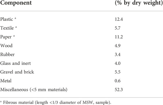
Solid waste was taken from a sanitary landfill on the outskirts of the Chinese city of Yancheng in order to prepare specimens for tests. The samples of solid waste from drilling holes were placed in plastic drums with tight seals and then transported to the laboratory. First, the collected MSW was treated, for instance, by removing the larger block bodies of wood, stone, bricks, textiles, metals, and plastic bottles, . Second, the remaining part was dried in an oven at 60 °C to a constant weight. Finally, Table 1 shows the percentages of plastic, textile, paper, wood, glass and inert, gravel and bricks, and other miscellaneous pastes that make up the collected MSW, as obtained by the manual sorting method.
To ensure all prepared MSW specimens have the same initial state, the reconstituted MSW specimens with a diameter of 40 mm and a height of 86 mm were measured using the conventional triaxial compression tests. According to the Technical Specification of Soil Test of Landfilled Municipal Solid Waste (Industrial Standard of the People’s Republic Of China (CJJ/T 204-2013)), the maximum particle size and the length of the fibrous materials’ (i.e., plastic and textiles) are, respectively, not larger than 1/8 and 1/3 of the specimens’ diameter. These prepared MSW specimens have a dry density of 0.69g/cm3, an initial void ratio of 2.0, and an initial moisture content of 50%.
2.2 Testing program
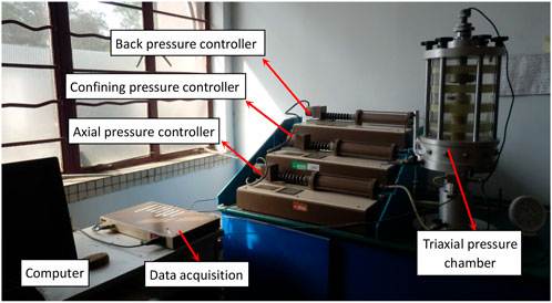
The consolidated drained (CD) CTXC tests were carried out for the reconstituted MSW specimens using consolation confining pressure of 100, 200, 300, and 400 kPa. Before tests, the MSW specimens were saturated in combination with vacuum pumping saturation, water head saturation, and back-pressure saturation methods. The detailed saturation methods were reported by Li and Shi. (2016). Then, the saturated specimens were placed in a triaxial pressure chamber to consolidate by applying a constant confining pressure until the volume change rate was negligible. Finally, the specimens were tested at a shearing rate of 0.02 mm/min after consolidation. The triaxial test apparatus is shown in Figure 1.
During tests, the axial strain
Under axisymmetric conditions, the mean normal effective stress p′ and the deviator stress q are defined as follows in Eq. 2.
3 Test results and discussion
3.1 Stress–strain and volume change behavior
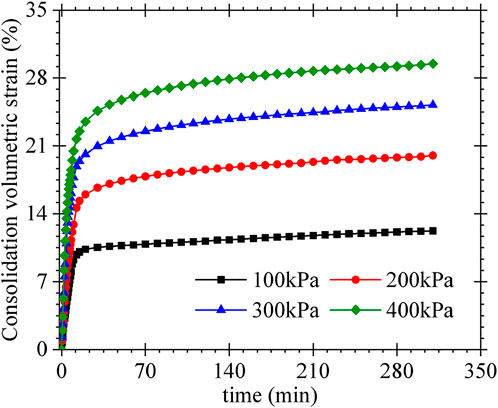
Figure 2 shows the variation of MSW volumetric strain with time during consideration under different confining stresses. It can be observed that the consolidation process of the MSW specimen could not be finished in a short time. The volume change is very large initially, and the primary consolidation is completed in 30 min. The volume change tends to be stable after 150 min. After 300 min, the proportion of volume change to the initial total volume of the MSW specimen is less than 0.01%, indicating that MSW specimen consolidation is complete. The larger the consolidation confining pressure, the larger the volume change of the MSW specimen. After the MSW specimen is consolidated, the CTXC tests are carried out under drainage conditions. Figure 3 presents the appearance of the MSW specimen before and after the test. The MSW specimen has a large compression deformation as shown in Figure 3B, and the lateral swelling is very small, which confirms the high compressibility of MSW. The stress–strain and volume change curves of MSW specimens at different confining pressures are shown in Figure 4.
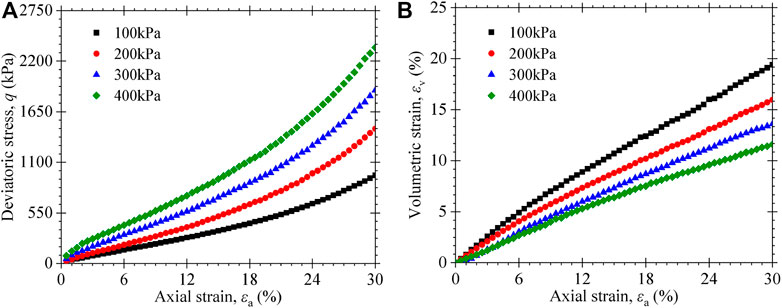
FIGURE 4. Triaxial test results of MSW specimens for different confining pressures: (A) deviatoric stress vs. axial strain; (B) volumetric strain vs. axial strain.
As shown in Figure 4, the stress–strain curves of the MSW specimen demonstrate strain-hardening behavior. The deviator stress continues to increase with axial strain without exhibiting any peak or tending to an asymptotic value even up to 30% axial strain. At the same axial strain, the specimen with larger confining pressure has higher deviatoric stress. As shown in Figure 4A, an upward curvature in stress–strain curves is observed since the axial strain is larger than 15%. When the axial strain exceeds 15%, the MSW specimen becomes requite dense, resulting in strong locking and squeezing effect between the fibrous materials and paste (i.e., soil-like components). Due to the fibrous material having higher tensile strength, the fibrous materials begin to play reinforcement at a larger strain level. The fibrous reinforcement can limit the lateral deformation of MSW specimens under loading. The larger the axial strain, the more pronounced the fibrous reinforcement. Hence, an upward curvature in stress–strain curves is observed at the larger axial strain.
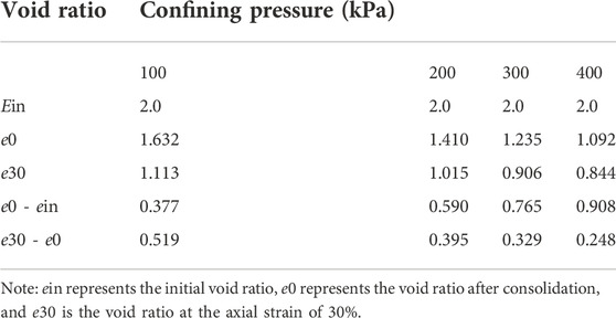
As shown in Figure 4B, the volumetric strain of the MSW specimen is also increasing continuously with the axial strain different from common soils, but its increase rate is decreasing gradually. The volumetric strain decreases with the increase of confining stress, similar to some results reported in the existing literature Machado et al. (2002); Vilar and Carvlho. (2004); Zhan et al. (2008); Karimpour-Fard et al. (2011), but it is just contrary to results found from common clay soils. The void ratios of MSW specimens are presented in Table2 before and after the consolidation and completion of compression shear test under different confining stresses. From Table 2 and Figure 4, the larger the confining pressure, the larger the volume change during consolidation, resulting in a smaller volume change during the compression shear test.
3.2 Effect of fibrous material on stress–strain–volume behavior
The effect of the fiber content (FC) (i.e., the percentage by dry weight of reinforcing materials) on the mechanical properties of MSW is studied using CD-CTXC tests. As shown in Figure 5, the experimental curves are obtained from the two kinds of solid waste with a fiber content of 17.8 and 0%. The stress–strain responses of MSW specimens with a non-fiber content exhibit an asymptotic value at a large axial strain without exhibiting upward curvatures, similar to a hyperbolic shape. The volumetric strain of MSW with non-fiber content is much smaller at larger strains than that of specimens with a fiber content of 17.8%.
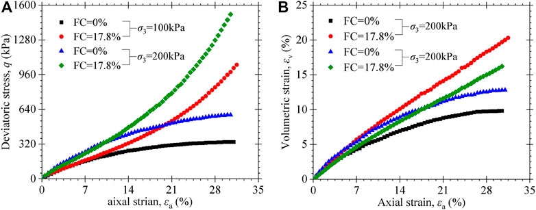
FIGURE 5. Triaxial test results of MSW specimens for different fibrous contents: (A) deviatoric stress vs. axial strain; (B) volumetric strain vs. axial strain.
Ramaiah and Ramana (2017) reported the stress–strain–volume change behavior of MSW specimens with different fibrous content (i.e., including 0, 1.8, 7.8, and 10.2%) using an automatic triaxial testing system. These MSW samples were excavated from Ghazipur and Okhla sanitary landfills located in Delhi, India. The age of MSW varied between 3 and 5.5 years. The measured dry unit weight of MSW is 7.5 kN/m3. All the MSW specimens have the same diameter of 70 mm and height of 140 mm. The specimens with different fiber content were subjected to saturation and then isotropically consolidated at a confining pressure of 50 kPa. The MSW specimens were sheared at a constant strain rate of 0.1%/min. As shown in Figure 6A, the stress–strain curves of MSW change gradually from strain-hardening to strain-softening behavior with decreasing fiber content. The deviatoric stress of MSW specimens with a high fiber content (i.e., FC = 10.2% and FC = 7.8%) increases continuously as the axial strain increases, and the increasing trend keeps even up to the axial strain of 30%. It should be noted that the MSW specimens with low or no fiber contents (i.e., FC = 0% and FC = 1.8%) exhibited failure or a tendency to fail, similar to that of conventional soils. Continuous increase in deviatoric stress for the MSW specimen with a high fiber content can be attributed to the reinforcing effect of the fibrous material, i.e., the tensile strength of fibrous materials contributes to the limit of specimen lateral deformation, similar to the mechanism observed in reinforced soils Shukla et al. (2009); Jamei et al. (2013) and fibrous peats Mesri and Ajlouni. (2007); O’Kelley and Zhang. (2013). As shown in Figure 6A, the specimen with high fiber content exhibits gradually higher shear strength with the axial strain. Thus, the reinforcing effect of the fibrous material appears gradually with the strain, and the fiber content plays a key factor to impact on the stress–strain behavior of MSW only at larger axial strain. The aforementioned analysis shows that the mechanical behavior of MSW is dependent on the performance of fibrous materials and paste. The mechanical properties of paste are similar to those of conventional soils, and the fiber content has an important impact on the stress–strain behavior. Therefore, the MSW can be regarded as a composite of fibrous materials and paste.
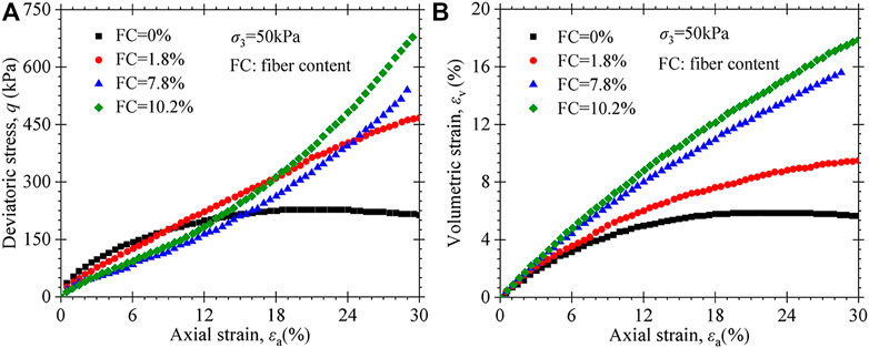
FIGURE 6. Test data from Ramaiah and Ramana21 (2017) for different fibrous contents at confining pressure of 50kPa: (A) deviatoric stress vs axial strain; (B) volumetric strain vs axial strain.
In addition, it can be seen from Figure 5B and Figure 6B that the volume change is also affected significantly by fiber content. The volumetric strains of MSW specimens having high fiber content continue to increase with axial strain. However, the volumetric strains of MSW specimens with low or non-fiber contents tend to be an asymptotic value toward large axial strains. It should also be noted that the volume change of MSW is significantly larger than that of conventional soils. Under the confining pressure of 50 kPa, for instance, the volumetric strain of the MSW specimen tested in this paper is 7.8% and that of conventional soils is only about 2%. It is worth emphasizing that MSW specimens with high fiber content have large volumetric strain compared to specimens with low or no fiber content. Under loading stress, the fibrous materials play a good role in the reinforcing effect, which can limit the lateral expansion deformation of MSW specimens. The higher the fiber content, the more pronounced the reinforcing effect, and the smaller lateral deformation for the MSW specimen. According to Eq. 1, hence, the MSW specimen with higher fiber content has produced larger volumetric strain at the same axial strain.
According to the test results of MSW with different fiber contents shown in Figure 3 and Figure 4, the fibrous reinforcement is gradually strengthened as the axial compression deformation and exhibits more pronounced fibrous reinforcement for MSW with high fiber content. Therefore, fibrous reinforcement is very necessary to be considered for developing the constitutive model, including the effect of fiber content, loading stress conditions, and shear deformation.
4 Proposed constitutive model
4.1 Hypothesis and features
As pointed out previously, the mechanical behavior of MSW is controlled by the fibrous materials (plastics and textiles) and paste (any other non-fibrous materials such as organic compounds, rubber, stone, glass, wood, and leachate). Thus, the constitutive model should consider MSW as a composite of two components. Several hypotheses and main features are presented here to develop the MSW constitutive model:
1) The characteristics of elastoplastic deformation of MSW obey the critical state soil mechanics theory as the same to common soils.
2) In the triaxial stress state, the mean effective normal stress
3) The variation of the MSW void ratio is only related to paste under loading. In other words, MSW volumetric strains are controlled exclusively by paste compression, which does not take into account the contributions of fibrous materials. MSW shear distortions are closely related to both fibrous material and paste.
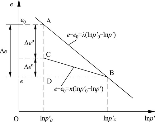
Figure 7 presents the
From Figure 7, the total compressive volumetric strain during the loading path of point A and point B is given by.
The elastic volumetric strain
and increment.
4.2 Constitutive model framework for MSW
From the second assumption, MSW total deviatoric stress q is equal to the sum of the deviator stresses supported by fibrous materials and paste; therefore,
where
Under the framework of critical soil mechanics theory, it is assumed that there is no recoverable energy associated with shear distortion (i.e., the elastic shear strain increment
According to the third assumption mentioned previously, it is assumed that there is a relationship among the MSW plastic shear strain increment
where
Similar to the literature reported by Machado et al. (2002), the relationship between
Substituting Eq. 12 into Eq. 11, that is.
where
Considering the plastic potential function of the modified Cam–Clay model, in combination with Eqs. 9, 14, and 15, a new plastic work dissipation function is developed as follows.
where Mp corresponds to the critical state ratio of the paste. It is assumed that the reinforcement of fibrous materials does not affect the critical state of the paste.
Using the normality condition
The plastic potential function g( ) can be obtained by solving the ordinary differential Eq. 17. According to the associated flow rule, the yield surface function f ( ) has the same expression as g ( ), which can be expressed as follows.
where
According to the normality condition, the evaluation of increments in plastic volumetric and shear stains are, respectively, expressed as follows.
where
Using Eqs. 20, 21, scalar
Substituting Eq. 22 into Eq. 20, the plastic volumetric and shear strain increments can be calculated as follows.
where
5 Determination of model parameters
5.1 Volume content of fibrous materials
Compared with the fibrous volume ratio
where
5.2 Fibrous action parameter Rf
Because it is reinforced with fibrous materials, the MSW has a unique mechanical behavior different from conventional soils. Because the volume change of MSW is entirely dependent on paste compression and the shear strain of MSW related to fibrous material and paste, the evaluations of
Using Eqs. 1 and 7, 9 and 10, the fibrous action parameter
The increment of
where a and b are the parameters related to the reinforced effect of fibrous materials, and parameter c reflects that the effect of reinforcement is nonlinear with the fiber content.
5.3 Critical state stress ratio of paste Mp
Bray et al. (2009) demonstrated that the shear strength that envelops the line of MSW is nonlinearly increased with normal stress with a concave downward characteristic, which cannot be described by the linear Mohr–Coulomb strength criterion. According to the strength envelope of MSW direct test results, Zekkos et al. (2010) assumed that cohesion c is constant and the internal friction angle
where
The paste critical state stress ratio Mp can be expressed by the friction angle
Figure 8 presents the variation of paste critical stress ratio Mp with Δφ at φc =30°. When the confining pressure is less than Pat, Mp increases linearly with Δφ; and when the confining pressure is larger than Pat, Mp decreases linearly with Δφ.
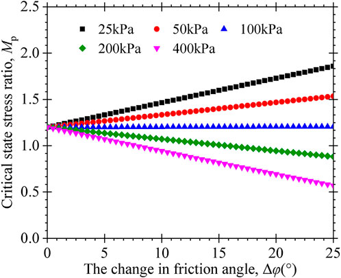
FIGURE 8. Evolution of the critical state stress ratio of paste with the internal friction angle change parameter of the paste under different confining stresses.
6 Model parameters and calibration
This constitutive model of MSW contains nine parameters, which can be directly measured or obtained by fitting the experimental data. There are five parameters same as those of the modified Cam–Clay model (i.e. e0,
6.1 Prediction of the MSW in this paper
To validate the MSW model, experimental data obtained in this study will be modeled first. The model parameters are listed in Table3. Figure 9 presents the modeled and experimental values for CTXC tests performed in this work. It can be seen that the stress–strain curves reproduced are clearly consistent with experimental curves, both quantitatively and in shape. The MSW model can well-describe the nonlinear characteristics of the stress–strain curves with a downward curvature at the small strain level and an upward curvature at the large strain level. Meanwhile, the volumetric strain is also clearly reproduced for continuously increasing with the axial strain. At this point, the MSW model adequately captured an interesting feature that the volumetric strain is larger for the lower confining pressure as opposed to that observed in conventional soils.
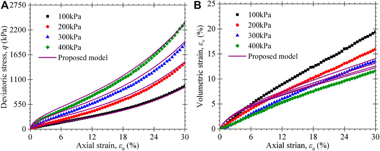
FIGURE 9. Experimental and predicted triaxial compression test results of MSW specimens in this paper: (A) stress–strain curves; (B) volumetric strain vs. axial strain curves.
6.2 Delhi MSW Ramaiah and Ramana (2017)
Ramaiah and Ramana (2017) reported the CTXC test data of MSW specimens under confining pressures of 25, 50, 100, 200, and 400 kPa, using an automatic triaxial testing system. The model parameters are shown in Table4. Figure 8 and Figure 9 show the comparison of the model-predicted and experimental data of MSW with a fiber content of 7.8 and 10.2%, respectively. It can be seen that a good reproduction of deviatoric stress is observed in Figure 10A and Figure 11A. The deviatoric stress increases with the axial strain, and the increasing trend accelerates continuously even at large axial strain. From Figure 10B and Figure 11B, it is observed that the volumetric strain continuously increases with the axial strain and a smaller volumetric strain is obtained for a higher confining stress case. These typical characteristics of stress–stain and volumetric strain behavior of MSW are captured by the proposed constitutive model considering the reinforcing effect of fibrous materials.
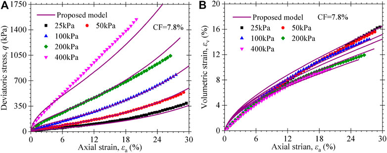
FIGURE 10. Experimental and predicted triaxial compression test results of MSW specimens with 7.8% fibrous content from Ramaiah and Ramana (2017): (A) stress–strain curves; (B) volumetric strain vs. axial strain curves.
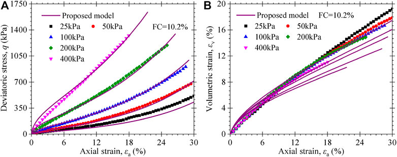
FIGURE 11. Experimental and predicted triaxial compression test results of MSW specimens with 10.2% fibrous content from Ramaiah and Ramana (2017): (A) stress–strain curves; (B) volumetric strain vs. axial strain curves.
6.3 Brazilian MSW Asadi et al. (2017)
The consolidated drained triaxial compression tests on Brazilian MSW were conducted by Asadi et al. (2017). The MSW was collected from the Bandeirantes landfill in São Paulo, Brazil, and the age of MSW was 15 years. The unit weight of the MSW was 12 kN/m3. The diameter and height of the MSW specimen were 150 and 300 mm, respectively. The confining pressures of 100, 200, and 400 kPa were adopted in the tests, and the vertical shear velocity was 0.7 mm/min. The experimental results were simulated by the proposed model, and the model parameters are listed in Table 5. As shown in Figure 12, the proposed model can well-predict the variation of stress–stain and volumetric strain behavior with the axial stain of MSW. However, the volumetric strain was overestimated for lower confining stress to a certain extent.
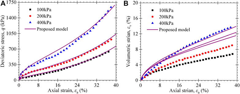
FIGURE 12. Experimental and predicted triaxial compression test results of MSW specimens with 25% fibrous content from Asadi et al. (2017): (A) stress–strain curves; (B) volumetric strain vs. axial strain curves.
6.4 Effect of the fiber content
The triaxial test results of MSW with different fiber contents are reproduced by the proposed model as shown in Figure 13 and Figure 14. For the MSW specimens tested in this work, Figure 13 presents that the calculations of the proposed model are in good agreement with the stress–strain–volume change behavior of MSW. For the MSW specimens measured by Ramaiah and Ramana (2017), as shown in Figure 14, the constitutive model can well-describe the stress–strain responses of MSW with higher fiber content (i.e., FC = 10.2% and FC = 7.8%). However, it has a much larger difference in the model compared with test data of MSW with low or no fiber contents (i.e., FC = 0% and FC = 1.8%). Nevertheless, the proposed constitutive model has captured the characteristics that the stress–strain response of MSW changes from strain-softening to strain-hardening strain behavior with the increasing fiber content gradually. The volume change behavior that MSW specimens with a higher fiber content exhibit larger volumetric strains compared to specimens with low or no fiber content is also reflected by the proposed model.
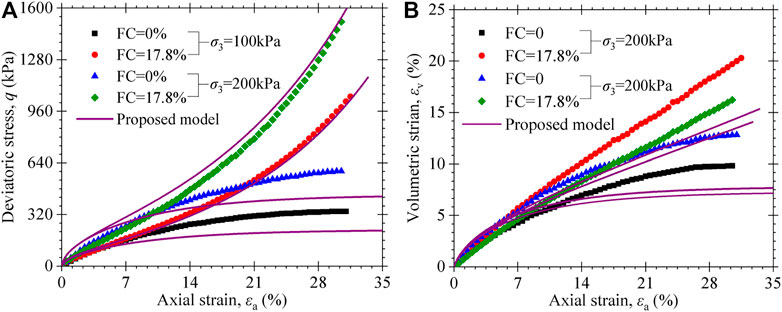
FIGURE 13. Experimental and predicted triaxial test results of MSW specimens with different fibrous content from this paper: (A) stress–strain curves; (B) volumetric strain vs axial strain curves.
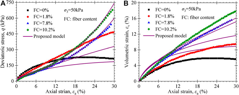
FIGURE 14. Experimental and predicted triaxial test results of MSW specimens with different fibrous content at a confining pressure of 50kPa from Ramaiah and Ramana (2017): (A) stress–strain curves; (B) volumetric strain vs. axial strain curves.
7 Model parameter analysis
7.1 Analysis of fibrous action parameters
As shown previously, the key factor in developing the model is considering the reinforcement effect of the fibrous material. Therefore, the model calculations will be affected by the parameters a, b, and c as observed from Eq. 26 since they control the reinforcement effect of the fibrous material in MSW. To highlight the influence of these parameters on the model responses, the parameters presented in Table 3 are adopted in the simulations at a confining pressure of 200kPa.
Since parameter c is approximately constant from Table 3 to Table 5, the influence of parameters a and b on the calculation of the proposed model is analyzed as follows. Figure 15 shows how parameters a and b, which are related to the reinforcement effect of fibrous material, influence the results of the proposed model. As shown in Figure 15A, the differences between deviator stress and volumetric strain are very less as the axial strain is less than 5%. The deviator stress and volumetric strain increase as the axial strain becomes larger than 5%. The larger the value of parameter a, the larger the deviator stress, and the more apparent the upward curvature in the stress–strain curves observed from Figure 15A. As the parameter a=0, the proposed constitutive model will degenerate into the modified Cam–Clay model, and the deviator stress and volumetric strain gradually trend a constant with the axial strain. As the parameter a≠0, the volumetric strain increases continuously with the axial strain, and a larger value of parameter a corresponded to a larger volumetric deformation. When the axial strain is 20%, the deviator stress increases by 1.5, 2.5, 3.5, and 4.5 times from 282kPa, and the volumetric strain increases from 10% to 11.5, 12.5, 13.5, and 14.5, as a=0 change to 4.8, 6.2, 7.6, and 9.4, respectively.
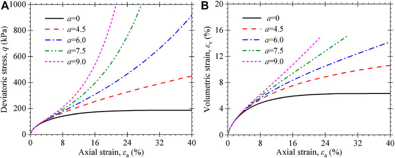
FIGURE 15. Influence of parameter a on the stress–strain behavior of MSW: (A) stress–strain curves; (B) volumetric strain vs. axial strain curves.
As can be observed from Figure 16, the deviator stress and volumetric strain increase with the values of b decreasing as the axial strain is larger than 5%. The smaller values of b correspond to the more apparent upward curvature in the stress–strain curves and the larger volumetric strain. When the b value is reduced to a certain extent (i.e., smaller than 0.02), the b value has relatively little importance on model predictions.
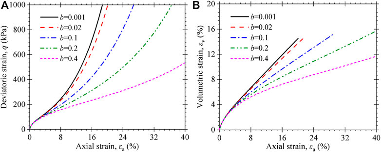
FIGURE 16. Influence of parameter b on the stress–strain behavior of MSW: (A) stress–strain curves; (B) volumetric strain vs. axial strain curves.
7.2 Analysis of paste action parameter
The fibrous materials and paste regulate the MSW’s mechanical behavior, as the aforementioned information demonstrates. Therefore, the model predictions are also affected by parameter Δφ since it reflects the critical stress state of the paste. Using the parameters listed in Table 3, Figure 17 and Figure 18 show how parameter Δφ influences the model responses as the confining pressure becomes higher and less than 1 atmospheric pressure. As the
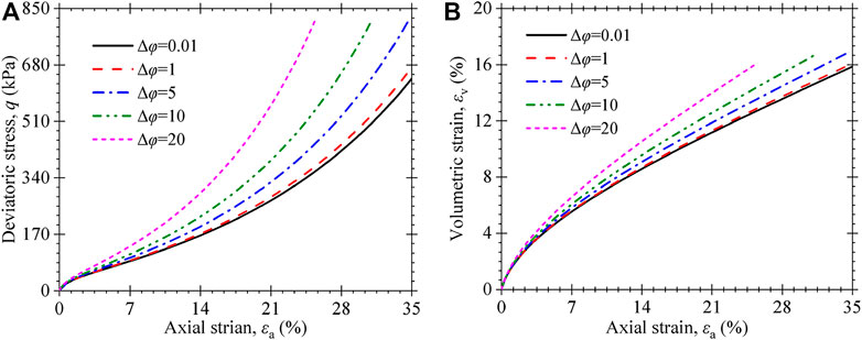
FIGURE 17. Influence of Δφ on the stress–strain behavior of MSW under confining stress of 50kPa; (A) stress–strain curves; (B) volumetric strain vs. axial strain curves.
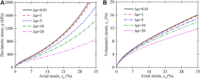
FIGURE 18. Influence of Δφ on the stress–strain behavior of MSW under a confining stress of 200kPa: (A) stress–strain curves; (B) volumetric strain vs. axial strain curves.
8 Conclusion
The stress–strain–volume change behavior of MSW reconstituted specimens was evaluated using CTXC tests. The MSW specimen without fibrous materials exhibits distinct failure or tendency to fail toward large axial strain, similar to conventional soils. Fiber content increase in MSW contributes to the reinforcement action causing the strain-hardening behavior, large shear strength, and large volumetric deformation. Fibrous reinforcement is the key factor to impact the mechanical behavior of MSW. MSW is regarded as a composite made up of fibrous materials (mainly plastics and textiles) and paste (the other non-fibrous components of MSW), whose mechanical behavior is controlled by the two kinds of materials.
This study proposes the concept and evaluation equation of the fibrous reinforcement action parameter Rf. The parameter Rf is introduced into a newly developed plastic potential function to deduce the constitutive model of MSW using the associated flow rules. Although the application of the proposed model needs to determine a considerable number of parameters, all of these parameters have physical meanings and can be determined by triaxial tests or one-dimensional compression tests. The proposed model can capture the main feature of stress–strain–volume change behavior and reproduce the laboratory experimental data. The model accurately reproduces the upward curvature in stress–strain responses and the continuing increase in volumetric strain with the axial strain, as well as volumetric strain is larger for the low confining pressure. It is also worth noting that the proposed model well-reflects the effect of the fiber content on the mechanical behavior of MSW, as the shear strength and volume change of MSW increase with the fiber content. Through comparison to experimental data, the proposed model can effectively simulate the mechanical and deformation properties of MSW.
Data availability statement
The original contributions presented in the study are included in the article/Supplementary Material. Further inquiries can be directed to the corresponding author.
Author contributions
XL: conceptualization, methodology, and writing—original draft preparation; BP: data curation and investigation; and BP and JL: supervision.
Acknowledgments
The authors appreciate the financial support provided by Youth Fund Project of National Natural Science Foundation of China (No.41807276).
Conflict of interest
The authors declare that the research was conducted in the absence of any commercial or financial relationships that could be construed as a potential conflict of interest.
Publisher’s note
All claims expressed in this article are solely those of the authors and do not necessarily represent those of their affiliated organizations, or those of the publisher, the editors, and the reviewers. Any product that may be evaluated in this article, or claim that may be made by its manufacturer, is not guaranteed or endorsed by the publisher.
References
Abreu, A. E. S., and Vilar, O. M. (2017). Influence of composition and degradation on the shear strength of municipal solid waste. Waste Manag. 68, 263–274. doi:10.1016/j.wasman.2017.05.038
Asadi, M., Shariatmadari, N., Karimpour-Fard, M., and Noorzad, A. (2017). Validation of hyperbolic model by the results of triaxial and direct shear tests of municipal solid waste. Geotech. Geol. Eng. (Dordr). 35 (5), 2003–2015. doi:10.1007/s10706-017-0223-y
Babu, G. L. S., Lakshmikanthan, P., and Santhosh, L. G. (2015). Shear strength characteristics of mechanically biologically treated municipal solid waste (MBT-MSW) from Bangalore. Waste Manag. 39, 63–70. doi:10.1016/j.wasman.2015.02.013
Babu, G. L. S., Reddy, K. R., and Chouksey, S. K. (2010). Constitutive model for municipal solid waste incorporating mechanical creep and biodegradation-induced compression. Waste Manag. 30 (1), 11–22. doi:10.1016/j.wasman.2009.09.005
Bray, J. D., Zekkos, D., Kavazanjian, E., Athansopoulos, G. A., and Riemer, M. F. (2009). Shear strength of municipal solid waste. J. Geotech. Geoenviron. Eng. 135 (6), 709–722. doi:10.1061/(asce)gt.1943-5606.0000063
Chen, Y. M., Zhan, L. T., and Gao, W. (2018). Waste mechanics and sustainable landfilling technology: Comparison between HFWC and LMWC MSWs. The international congress on environmental geotechnics. Proc. 8thInternational Congr. Environ. Geotechnics 1, 3–37.
Chn, N. B. S. (2018). Resources and environment in China: 2017 facts and figures. China statistical yearbookBeijing: National Bureau of Statistics of ChinaChina Statistical Press.
Chouksey, S. K., and Babu, G. L. S. (2015). Constitutive model for strength characteristics of municipal solid waste. Int. J. Geomech. 15 (2), 04014040. doi:10.1061/(asce)gm.1943-5622.0000351
Dixon, N., and Jones, D. R. V. (2005). Engineering properties of municipal solid waste. Geotext. Geomembranes 23 (3), 205–233. doi:10.1016/j.geotexmem.2004.11.002
Feng, S. J., Gao, K. W., Chen, Y. X., Li, Y., Zhang, L. M., and Chen, H. X. (2017). Geotechnical properties of municipal solid waste at laogang landfill, China. Waste Manag. 63, 354–365. doi:10.1016/j.wasman.2016.09.016
Industrial Standard of the People’s Republic Of China (CJJ/T 204-2013), , (2013). Technical specification of soil test of landfilled municipal solid waste. Beijing; Issued by the ministry of housing and Urban Rural Development of the People’s Republic of China.
Jamei, M., Villard, P., and Guiras, H. (2013). Shear failure criterion based on experimental and modeling results for fiber-reinforced clay. Int. J. Geomech. 13 (6), 882–893. doi:10.1061/(asce)gm.1943-5622.0000258
Karimpour-Fard, M., Machado, S. L., Shariatmadari, N., and Noorzad, A. (2011). A laboratory study on the MSW mechanical behavior in triaxial apparatus. Waste Manag. 31 (8), 1807–1819. doi:10.1016/j.wasman.2011.03.011
Ke, H., Guo, C., Chen, Y., Ling, D., and Pan, Y. (2014). A nonlinear constitutive model for municipal solid waste considering effects of degradation. Rock Soil Mech. 35 (5), 1217–1223.
Li, X., and Shi, J. (2016). Stress-strain behaviour and shear strength of municipal solid waste (MSW). KSCE J. Civ. Eng. 20 (5), 1747–1758. doi:10.1007/s12205-015-0268-5
Lü, X., Zhai, X., and Huang, M. (2017). Characterization of the constitutive behavior of municipal solid waste considering particle compressibility. Waste Manag. 69, 3–12. doi:10.1016/j.wasman.2017.08.003
Machado, S. L., Carvalho, M. F., and Vilar, O. M. (2002). Constitutive model for municipal solid waste. J. Geotech. Geoenviron. Eng. 128 (11), 940–951. doi:10.1061/(asce)1090-0241(2002)128:11(940)
Machado, S. L., Vilar, O. M., and Carvalho, M. F. (2008). Constitutive model for long term municipal solid waste mechanical behavior. Comput. Geotechnics 35 (5), 775–790. doi:10.1016/j.compgeo.2007.11.008
Machado, S. L., Vilar, O. M., Carvalho, M. F., and Karimpour-Fard, M. (2017). A constitutive framework to model the undrained loading of municipal solid waste. Comput. Geotechnics 85 (2), 207–219. doi:10.1016/j.compgeo.2016.12.002
Mesri, G., and Ajlouni, M. (2007). Engineering properties of fibrous peats. J. Geotech. Geoenviron. Eng. 133 (7), 850–866. doi:10.1061/(asce)1090-0241(2007)133:7(850)
OECD (Organization for Economic CO-Operation and Development) (2017). https://stats.oecd.org/.
O’Kelley, B. C., and Zhang, L. (2013). Consolidated-drained triaxial compression testing of peat. Geotech. Test. J. 36 (3), 53–64. doi:10.1520/gtj20120053
Ramaiah, B. J., Ramana, G. V., and Datta, M. (2017). Mechanical characterization of municipal solid waste from two waste dumps at Delhi, India. Waste Manag. 68, 275–291. doi:10.1016/j.wasman.2017.05.055
Ramaiah, B. J., and Ramana, G. V. (2017). Study of stress-strain and volume change behavior of emplaced municipal solid waste using large-scale triaxial testing. Waste Manag. 63, 366–379. doi:10.1016/j.wasman.2017.01.027
Reddy, K. R., Gangathulasi, J., Parkalla, N. S., Hettiarachchi, H., Bogner, J. E., and Lagier, T. (2009). Compressibility and shear strength of municipal solid waste under short-term leachate recirculation operations. Waste Manag. Res. 27 (6), 578–587. doi:10.1177/0734242x09103825
Reddy, K. R., Hettiarachchi, H., Gangathulasi, J., and Bogner, J. E. (2011). Geotechnical properties of municipal solid waste at different phases of biodegradation. Waste Manag. 31 (11), 2275–2286. doi:10.1016/j.wasman.2011.06.002
Reddy, K. R., Hettiarachchi, H., Giri, R. K., and Gangathulasi, J. (2015). Effects of degradation on geotechnical properties of municipal solid waste from orchard hills landfill, USA. Int. J. Geosynth. Ground Eng. 1 (3), 24. doi:10.1007/s40891-015-0026-2
Shariatmadari, N., Asadi, M., and Karimpour-Fard, M. (2017). Investigation of fiber effect on the mechanical behavior of municipal solid waste by different shearing test apparatuses. Int. J. Environ. Sci. Technol. (Tehran). 14 (6), 2239–2248. doi:10.1007/s13762-017-1297-z
Shariatmadari, N., Machado, S. L., Noorzad, A., and Karimpour-Fard, M. (2009). Municipal solid waste effective stress analysis. Waste Manag. 29 (12), 2918–2930. doi:10.1016/j.wasman.2009.07.009
Shukla, S., Sivakugan, N., and Das, B. (2009). Fundamental concepts of soil reinforcement-an overview. Int. J. Geotechnical Eng. 3 (3), 329–342. doi:10.3328/ijge.2009.03.03.329-342
Singh, M. K., Vilar, O. M., and Carvalho, M. F. (2011). Application of a hyperbolic model to municipal solid waste. Geotechnique 61 (7), 533–547. doi:10.1680/geot.8.p.051
Song, D. Q., Dong, L. H., and Feng, X. B. (2019). Approach to the application of ultrasonic technology to measuring physical properties of new building materials. Indian J. Geo-marine Sci. 48 (5), 739–746.
US. EPA, (2016). Municipal solid waste in the United States: 2015 facts and figures. Washington, DC: United States Environmental Protection Agency.
Vilar, O. M., and Carvlho, M. (2004). Mechanical properties of municipal solid waste. J. Test. Eval. 32 (6), 348–449. doi:10.1520/jte11945
Xiang, G. S., Song, D. Q., and Chen, Z. (2021). Investigated stress-strain relationships of municipal solid waste incineration bottom ash. Geomat. Nat. Hazards Risk 11 (1), 2431–2448. doi:10.1080/19475705.2020.1845823
Xiang, G. S., and Song, D. Q. (2020). Experimental study on the strength behaviors of municipal solid waste incineration bottom ash using ultrasonic wave velocity tests. Geomat. Nat. Hazards Risk 11 (1), 1581–1598. doi:10.1080/19475705.2020.1805516
Zekkos, D., Athanasopoulos, G. A., Bray, J. D., Grizi, A., and Theodoratos, A. (2010). Large-scale direct shear testing of municipal solid waste. Waste Manag. 30 (8), 1544–1555. doi:10.1016/j.wasman.2010.01.024
Zekkos, D., Bray, J. D., and Riemer, M. F. (2012). Drained response of municipal solid waste in large-scale triaxial shear testing. Waste Manag. 32 (10), 1873–1885. doi:10.1016/j.wasman.2012.05.004
Zekkos, D., and Fei, X. (2017). Constant load and constant volume response of municipal solid waste in simple shear. Waste Manag. 63, 380–392. doi:10.1016/j.wasman.2016.09.029
Zhan, T. L. T., Chen, Y. M., and Ling, W. A. (2008). Shear strength characterization of municipal solid waste at the suzhou landfill, China. Eng. Geol. 97 (3), 97–111. doi:10.1016/j.enggeo.2007.11.006
Zhang, Z., Guo, W., Zhang, Y., Wu, D., Xu, H., Liu, K., et al. (2019). Shear strength behavior of mechanical-biological treated waste in triaxial tests. Chin. J. Geotechnical Eng. 41 (4), 2170–2179.
Zhang, Z., Zhang, Y., Guo, W., Wu, D., Xu, H., and Wang, Y. (2018). Laboratory study on the geotechnical properties of MBT waste. Chin. J. Rock Mech. Eng. 37 (9), 2170–2179.
Zhao, Y. R., Xie, Q., Wang, G. L., Zhang, Y. J., Zhang, Y. X., and Su, W. (2014). A study of shear strength properties of municipal solid waste in Chongqing landfill, China. Environ. Sci. Pollut. Res. 21 (22), 12605–12615. doi:10.1007/s11356-014-3183-2
Glossary
a, b, c(-) Fiber-reinforced effect parameters
Keywords: municipal solid waste (MSW), triaxial compression tests, fibrous reinforcement, stress–strain behavior, constitutive model
Citation: Li X, Peng B and Li J (2023) Constitutive model for stress–Strain responses of municipal solid waste considering fibrous reinforcement. Front. Earth Sci. 10:1059234. doi: 10.3389/feart.2022.1059234
Received: 01 October 2022; Accepted: 31 October 2022;
Published: 17 January 2023.
Edited by:
Maxim Lebedev, Curtin University, AustraliaCopyright © 2023 Li, Peng and Li. This is an open-access article distributed under the terms of the Creative Commons Attribution License (CC BY). The use, distribution or reproduction in other forums is permitted, provided the original author(s) and the copyright owner(s) are credited and that the original publication in this journal is cited, in accordance with accepted academic practice. No use, distribution or reproduction is permitted which does not comply with these terms.
*Correspondence: Bo Peng, MTU0MzMwNTc2MEBxcS5jb20mI3gwMjAwYTs=
 Xiulei Li
 Bo Peng
 Jinfeng Li3