 Mingwei Guo
 Xuechao Dong
 Zhi Yang
94% of researchers rate our articles as excellent or good
Learn more about the work of our research integrity team to safeguard the quality of each article we publish.
Find out more
ORIGINAL RESEARCH article
Front. Earth Sci., 05 January 2023
Sec. Geohazards and Georisks
Volume 10 - 2022 | https://doi.org/10.3389/feart.2022.1056695
This article is part of the Research TopicGeological Disasters in Deep Engineering Mechanism, Warning and Risk mitigationView all 39 articles
With the increasing size of open caissons in large-span bridge projects, the overall settlement of giant open caissons is vital to the safe construction of bridge superstructures. Taking the engineering case of the Changtai Yangtze River Bridge, the overall deformation of an open caisson was studied during the construction stage of the bridge’s superstructures. First, the theoretical layer-wise summation method was utilized to analyze the settlement of the open caisson. Then, a 3-D finite element model was established to simulate the installation stage of the bridge superstructure. Finally, a large centrifuge model test was performed to obtain the deformation of the open caisson at each step of bridge’s construction. The results of these approaches demonstrated that final settlements were quite consistent—approximately 225 mm when the bridge superstructure was completely installed—and the settlement deformation curve could be divided into three stages: slowly increasing, rapid, and stabilizing. This study can provide significant guidance for the construction of the Changtai Yangtze River Bridge and be a reference for similar open caisson engineering projects.
Open caissons are used for the foundations of the deep piers of bridges or other heavy structures when their bearing beds are deep under the soil surface or below water (Nonveiller, 1987). Open caissons have the advantage of good integrity, high structural stiffness, high bearing capacity, small deformation, and full utilization of internal space (Mu et al., 2015; Li et al., 2020). In recent years, they have been widely applied in deep foundations and underground structural engineering projects; they have become one of the main types of foundation in long-span bridge engineering projects (Allenby et al., 2009; Jiang et al., 2019).
Table 1 shows the statistics of the principal open caisson projects around the world and shows that many open caissons have been used in long-span bridges in China since 2000 and for many major bridge projects. It can be anticipated that many more giant open caissons will appear one after another with the development of future long-span bridges. As a result, the overall settlement of open caissons has become a key issue in bridge construction and is of great significance for the reasonable assessment of the settlement deformation of caisson foundations to ensure the safe installation of bridge superstructures.
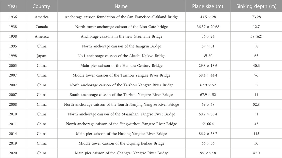
TABLE 1. Statistical table of the main open caissons around the world.
Research into open caissons has mainly been twofold. One aspect has focused on the sinking process of the open caisson, and the other, on the deformation behavior of the open caisson after sinking to the desired depth. The sinking process of open caissons has been studied by theoretical analysis, laboratory tests, numerical analysis, and the analysis of field monitoring data to determine the mechanical responses and deformation characteristics of the surrounding soil that are induced by the installation of open caissons (Yan and Shi, 2013; Jiang, et al., 2019; Zhou et al., 2019; Royston et al., 2020; Guo et al., 2021; Templeman et al., 2021). Due to this focus on settlement deformation after sinking to the desired depth, studies on the sinking process of open caissons are not described in detail in this paper.
The bearing capacity of the foundation soil and the deformation behavior of an open caisson after sinking to the desired depth during the installation of a bridge superstructure have been comprehensively studied. Alampalli and Peddibotla (1997) conducted experiments on the settlement and deflection behavior of open-ended caissons in sandy soil. Solov’ev (2008) studied the bearing capacity of the foundation soil beneath the cutting edge of an open caisson using limit equilibrium theory, and Chavda et al. (2019) carried out a series of model tests to study the vertical bearing capacity and the soil flow mechanism around the cutting edge of an open caisson. Moreover, for offshore caisson foundations, the bearing capacity under combined V–H–M (vertical–horizontal–moment) loads was studied in clay (Zhang et al., 2011; Hung and Kim, 2014; Fu et al., 2018; Skau et al., 2018), sand (Cheng and Cassidy, 2016; Park et al., 2016; Jin et al., 2019), in sand over clay (Qiu and Henke, 2011; Park and Park, 2017; Zou et al., 2018), and in stiff over soft clay (Xia, et al., 2021). Some studies have also investigated the dynamic response of large embedded foundations (caisson foundations and anchorage open caissons) under horizontal and vertical vibrations (Apsel and Luco, 1987; Latini and Zania, 2017; Chen et al., 2007; Senjuntichai et al., 2006; Bilotta et al., 2015; Chen et al., 2019). To date, few studies have investigated the settlement deformation of caisson foundations after sinking to the desired depth during the installation of bridge superstructures (Chuanbao, 2021). However, it is vitally important to the safe installation of bridge superstructures to determine the overall settlement of open caissons.
The aim of this study is to investigate the deformation characteristics of open caissons during the installation of large-span bridge superstructures. The Changtai Yangtze River Bridge is presently under construction. It is a cable-stayed bridge with the longest span in the world, and giant open caissons were used under the main piers of this bridge (Figure 1). To reasonably assess the deformation characteristics of the open caissons during the installation of a large-span bridge superstructure, theoretical layer-wise summation was first used, and then, the 3D finite element technique was employed. Finally, a large centrifuge model test was performed to validate the results by theoretical methods and numerical analysis. More importantly, it played an important role in the installation of bridge superstructures by determining settlement deformations of the open caisson studied in this paper, and it also has importance as a significant reference for similar open caisson projects.
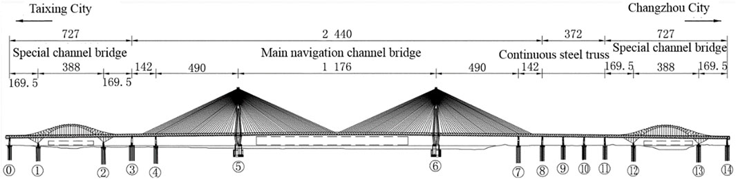
FIGURE 1. Main sections of the Changtai Yangtze River Bridge (units: m).
Figure 1 shows the overall layout of the Changtai Yangtze River Bridge that connects Changzhou City and Taixing City. It is a rail-cum-road cable-stayed bridge with an asymmetric layout of double towers and double cable planes. The lower layer of the bridge contains an intercity railway and an ordinary two-way four-lane road; its upper layer contains a two-way six-lane expressway. At present, it is the largest cable-stayed bridge in the world, with a span of 1,176 m. In Figure 1, the sections numbered ⑤ and ⑥ are the open caissons under the main piers of this bridge.
The main pier of the bridge is located on typically deep and sedimentary soil. To satisfy the action of the huge load of the bridge structure and meet the strict requirements of bridge alignment, an open caisson was proposed for use under the main pier through comprehensive technical and economic considerations (Qin et al., 2020).
The Yangtze River at the bridge site has an irregular semi-diurnal shallow-sea tidal pattern. The tide rises and falls twice a day, with a maximum tidal level of +5.28 m, minimum level of −1.14 m, and average level of +1.69 m.
The Quaternary overburden soil layer is widely distributed in the engineering field. Due to several past sea transgressions, the soil layers have changed in an orderly but complex manner. The main soils are alluvial clayish soil and sandy soil, and the underlying bedrock is mainly Neogene siltstone. At the bridge site, the thickness of the Quaternary loose sediment is more than 160 m, with strata of interbedded clay and sand. The upper part has a hard plastic silty clay layer with a thickness of 4 m
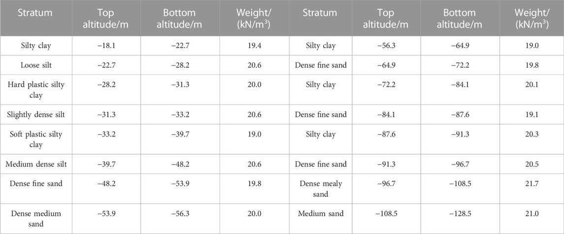
TABLE 2. Stratigraphic distribution.
From this stratigraphic distribution, it is evident that, above –40 m elevation, there are interlayers of silty clay with soft
According to the strata distributions under the main pier of the bridge and its load superstructure, it was suggested that the open caisson be sunk at –65 m elevation for the deformation requirement of the open caisson to be met. Therefore, the soft plastic silty clay with 12 m thickness between –72 m and –84 m elevation became the focus of the design of the open caisson foundation, which affected the caisson's investment and construction period. It thus became necessary to reasonably evaluate the settlement deformation of open caissons to provide strong technical support for the bridge’s construction.
A round-end plane shape for the open caisson was adopted for the Changtai Yangtze River Bridge. The stepped caisson foundation was first designed with a small top and a large base; its bottom surface is 95 m long across the bridge and 57.8 m wide along the bridge, and the radii of the circular ends are 28.9 m. The top surface is 77 m long and 39.8 m wide, and the radii of the circular ends are 19.9 m. The total height of the caisson foundation is 72 m, of which the lower step is 43 m and the upper step is 29 m. Steel shell concrete was used for the caisson foundation from top to bottom—currently the largest underwater steel caisson foundation in the world. It contains 36 compartments, including 18 inner shafts and 18 outer shafts (Figure 2).
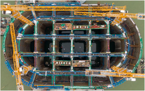
FIGURE 2. Open caisson at the field site.
The layer-wise summation method divides the soil into several layers based on its stratigraphic distribution and stress state within the influence depth of the foundation settlement. This method calculates the settlement of each layer separately and sums all settlements as the final settlement of the foundation. This method, which was written in the specific code for the design of building foundations in China (GB50007-2011), was applied and verified to be rational for practical foundation engineering.
The calculation formula of this method is shown as Eq. 1.
where S is the final settlement of the foundation (mm),
It can be seen from Eq. 1that the soil compressive modulus
where
According to the actual strata distributions in the area of the open caisson, the compressive modulus of each layer of soil was obtained based on uniaxial compression tests of the soil, which were calculated by Eq. 3 and are shown in Table 3. In Table 3,
where
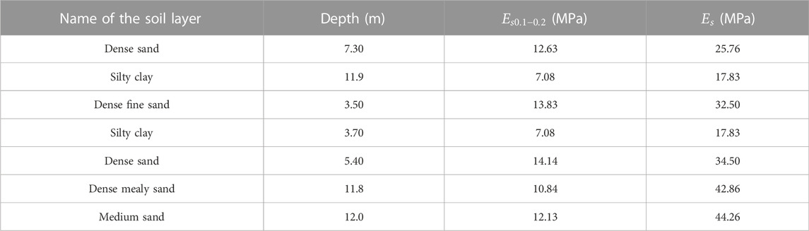
TABLE 3. Compression modulus.
It is known that the compressive modulus
Accordingly, for the open caisson under the main pier of the Changtai Yangtze River Bridge, the settlement of the open caisson was calculated by layer-wise summation at the installation stage of the bridge superstructure. The influence depth of the foundation settlement was 62 m, based on the actual strata distributions, and the empirical coefficient
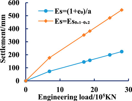
FIGURE 3. Load vs. settlement using different modulus values.
A 3-D finite element numerical method was also used to assess the deformation characteristics of the open caisson during the installation stage of the bridge superstructure in the Changtai Yangtze River Bridge project.
The size of the foundation is as follows: the bottom is 95 m long across the bridge, 57.8 m wide along the bridge, and the radii of the circular ends are 28.9 m. The top surface is 77 m long and 39.8 m wide, and the radii of the circular ends are 19.9 m. The total height is 72 m, of which the lower step is 43 m, the upper step is 29 m, and the target sinking elevation is −65 m.
Due to the focus on the deformation characteristics of open caissons during the installation stage of the bridge superstructure, the open caisson was simplified to be a solid structure based on equivalent bulk density. Considering the actual size of this foundation and the boundary effect of finite element analysis, a 3-D calculation model was established (Figure 4), the size of which is 560 m×560 m×300 m—length×width×height. PLAXIS 3D software was used to numerically analyze the deformation of the open caisson under the bridge loads. Figure 5 shows the finite element mesh model, and 10-node tetrahedral elements were utilized in the calculation model.
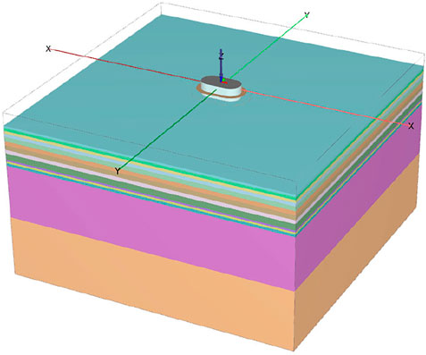
FIGURE 4. 3-D calculating solid model of a large stepped open caisson.
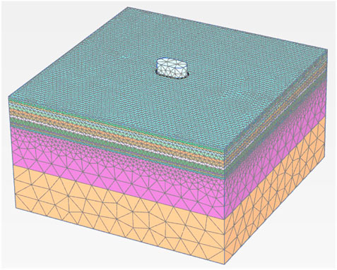
FIGURE 5. 3-D finite element mesh model.
For constitutive models of soils, the ideal elastic‒plastic constitutive model based on the Mohr‒Coulomb strength failure criterion is popularly applied in geotechnical engineering, although it does not consider the effects of the stress path and strain hardening on the mechanical properties of the soil. However, in practical engineering, there are strain hardening phenomena in the process of soil deformation under external loads. The hardening constitutive model of small strain soil (HSS), which is different from the Mohr‒Coulomb model, was developed on the basis of the hardening soil model (HS) first proposed by Benz (2006). The HSS model has the advantages of reflecting the compression characteristics and dilatancy of soil, distinguishing the loading and unloading stiffness, and considering the shear hardening and compression hardening at the same time—these can effectively reflect the mechanical properties of soil in triaxial and consolidation tests, especially the dependence of soil stiffness on the stress path. Furthermore, the HSS model has been verified to be rational, and the results were consistent with the practical deformation in foundation engineering (Mu and Huang, 2016; Fan and Zhai, 2019). To reasonably simulate the mechanical behavior of the bottom soil of an open caisson during the construction stage of long-span bridge engineering, the hardening constitutive model of small strain soil (HSS) was used to analyze the deformation of the caisson foundation.
The HSS model inherits all the characteristics of the HS model and accounts for the increase in soil stiffness in the small strain stage. The HSS model has some advantages over other models in soil shear hardening, compression hardening, loading and unloading, and small strain deformation. In recent years, practical engineering cases have demonstrated that the HSS model is more suitable for simulating the mechanical behavior of the soil in deep foundation engineering.
There are 13 soil parameters needed in the HSS model; except for the two small strain parameters of the HSS model, 11 of these are the same as those of the HS model. Based on field investigation, indoor tests of the soil, and existing research on the determination of soil parameters in the HSS model, the soil parameters are listed in Table 4. According to a previous study (Wang et al., 2012; Lian-xiang et al., 2019), the loading and unloading tangent modulus
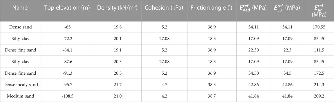
TABLE 4. Soil parameters.
For the boundary conditions of the calculating model, the bottom is completely restricted, and the rest are normal constraints. To reasonably assess the mechanical interactions between the soil and the open caisson, the contact between them was considered, and, in PLAXIS 3D software, the strength reduction factor
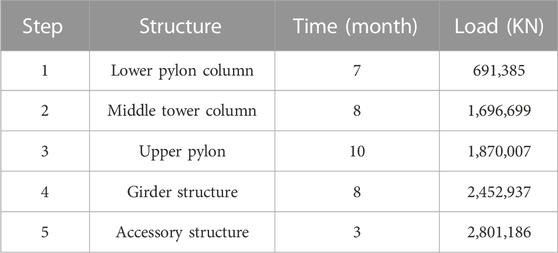
TABLE 5. Construction schedule of the main navigation channel bridge.
During the construction of the main navigation channel bridge, the settlement deformation was simulated by gradually applying vertical loads on the top surface of the open caisson. Figure 6 shows the vertical deformation at the different installation steps of the bridge superstructure. It can be seen in these figures that the vertical displacement is symmetrical because of the symmetry of the bridge structure and engineering loads; furthermore, the settlement of the open caisson gradually increased with the installation of the bridge superstructure. The final settlement of the open caisson foundation was 225.7 mm after finishing the main navigation channel bridge construction.
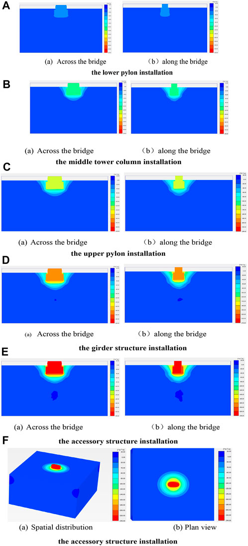
FIGURE 6. Isochromatic map of the vertical displacement distribution of the open caisson: (A) lower pylon installation; (B) middle tower column installation; (C) upper pylon installation; (D) girder structure installation; (E) accessory structure installation; (F) accessory structure installation.
The maximum settlement amounts of the open caisson during the installation of the bridge superstructure are listed in Table 6. To compare the settlement amounts by finite element analysis with those by the layer-wise summation method, the settlement comparison is presented in Figure 7. Figure 7 shows that the settlement amounts determined by the layer-wise summation method were larger than those determined by numerical analysis with the installation of the bridge superstructure; however, when the main navigation channel bridge was completed, the final settlement amounts determined by numerical analysis agreed well with those determined by finite element analysis. Moreover, the relative errors between the settlements by both methods gradually decreased, and the relative error of the final settlement was only approximately 0.5%.
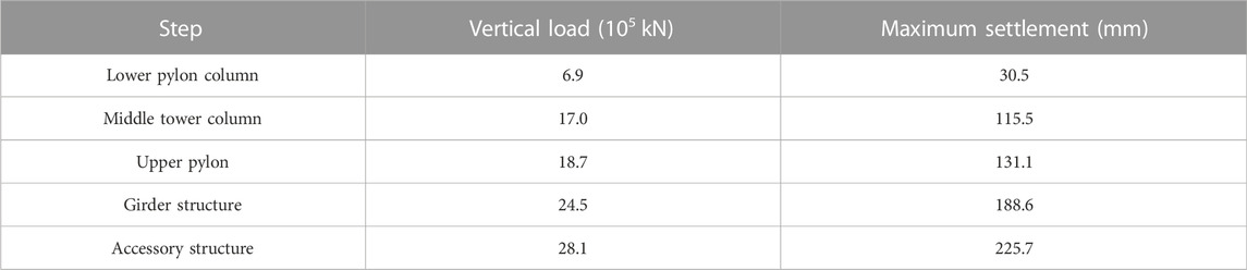
TABLE 6. Settlement amounts corresponding to different installation steps.

FIGURE 7. Settlement comparison of both methods.
To rationally evaluate the settlement deformation of the open caisson during the installation of the bridge superstructure, a large centrifuge model test was especially designed and conducted based on its actual size and engineering geological conditions. Figure 8 shows the large geotechnical centrifuge equipment (TK-C500). The maximum acceleration was 250 g. Here, g is gravity acceleration, the maximum effective load is 50 kN, the maximum radius of rotation is 5 m, and the maximum size of the model box is 1.2 m×1.0 m×1.2 m (length×width×height). The total weight of the open caisson used in this bridge is approximately 0.5 million tons, and the construction period was approximately 21 months. The total weight of the bridge superstructure is approximately 0.28 million tons, and the installation period was approximately 38 months.
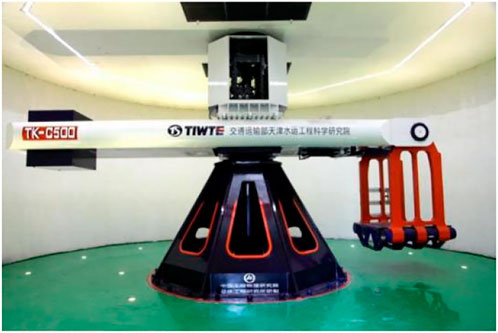
FIGURE 8. TK-C500 geotechnical centrifuge equipment.
The size of the open caisson is 95 m×57.8 m×72 m (length×width×height), and the size of the model box is 1.2 m×1.0 m×1.2 m (l×w×h). Taking the influence of the boundary effect into account, half of the symmetrical open caisson was modeled in the centrifuge test; based on the sizes of the open caisson and model box of the centrifuge equipment, the similarity ratio was comprehensively selected as 150, that is, the acceleration of the centrifuge was 150 g when the equipment was running steadily in the test process.
Figure 9 shows the solid model of the open caisson based on the design of the open caisson. Given the similarity ratio and the actual size of the open caisson, the size of the model is 317 mm×385 mm ×480 mm (l×w×h) made with 6,061 aluminum alloy material.
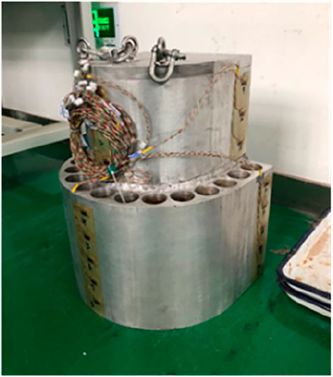
FIGURE 9. Solid model of the open caisson.
The physical and mechanical parameters of the soils were determined by indoor geotechnical tests after field drilling and sampling, and the clay and sand used in the model test were based on the corresponding physical and mechanical parameters of the soils. Before making the foundation model, drainage equipment was placed at the bottom of the model box to ensure saturation after completing the model. To reduce the influence of the boundary effect on the test model, Vaseline was applied to the inner wall of the model box to simulate a semi-infinite field (Figure 10).
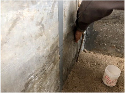
FIGURE 10. Vaseline applied to the wall of the model box.
For the foundation soils placed in the test model, a conventional sand-pouring method was used to produce the sand layer, and the vibration compaction method was used for the silty clay layer.
(1) Conventional sand pouring method for sand
The sand in the model box was placed by using the sand pouring method, which is related to the compactness and failing distance of the sand. To ensure the uniformity of the sand samples, the falling distance was calibrated in advance before placing the sand in the model box, and compaction was carried out to control the relative compactness of the sand. The preprepared sand samples were then loaded into the sand box, which was lifted to the specified initial height, and the circular sand-drop sieve mouth was used to place the sand. Later, the height of the sand rainier was gradually adjusted to maintain the falling distance of the sand. The process of placing the sand is shown in Figure 11.
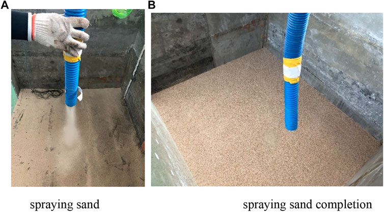
FIGURE 11. Sand placement process: (A) spraying sand; (B) spraying sand completion.
(2) Compaction method for silty clay
For the silty clay, the vibration compaction method was used to prepare the soil samples in the model. The soil in this method needs to be compacted layer by layer, with the dry density at the site used as the controlling parameter of the soil. To keep the parameters of the soil consistent, it was necessary to ensure that the compaction times were the same in the different parts of the same layer of soil (Figure 12A). After the preparation of one layer of silty clay, the surface of the soil needed to be scraped to increase the biting degree of the soil (Figure 12B).
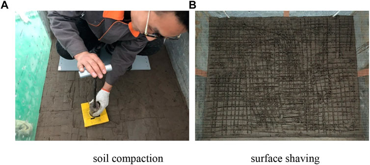
FIGURE 12. Silty clay placement process: (A) soil compaction; (B) surface shaving.
After the soil compartments were completely filled, water was slowly injected from the bottom of the model box upward to avoid disturbing the sand layer or creating bubbles in it. Sufficient water was injected to guarantee that the water surface was 1 cm higher than the top surface of the soil; thence, the water injection was stopped, and the soil model was soaked for 24 h. Before commencing the centrifuge model test, to ensure that the soil model was fully saturated, the water was again injected through the water pipe at the bottom of the model box until the water surface was 1 cm higher than the top surface of the soil model. Finally, the centrifugal testing machine was operated for 30 min under 150 g conditions to fully saturate the soil model. Figure 13 shows the solid model after completing the open caisson and soil model.
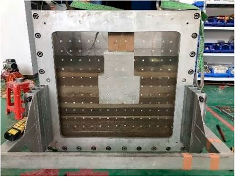
FIGURE 13. Completion of the model test.
During the centrifuge model test, a laser displacement sensor was used to monitor the settlement of the open caisson, and the earth pressure sensor was used to monitor the earth pressure in the silty clay under the open caisson.
Figure 14A shows the locations of four laser displacement sensors on the upper surface of the open caisson in the model test. The sensors were HG-C1200 laser sensors with a range of 200 ± 80 mm. Under the open caisson is a layer of silty clay approximately 12 m thick, which was a primary concern for this model test. Therefore, six mini earth-pressure sensors with a measuring range of 2 MPa were arranged on the surface and in the middle of the silty clay in this test (Figure 14B).
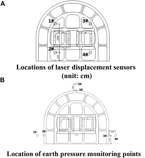
FIGURE 14. Locations of monitoring points (units:cm): (A) laser displacement sensor; (B) earth pressure sensor.
The loading system of the centrifuge model test was mainly composed of the frame above the model box, the loading beam, the loading equipment placed on the beam, and the controller. When the soil model was assembled, the hydraulic loading system was installed and simultaneously tested. This loading system was controlled by the feedback signals from the force and displacement sensors. Furthermore, based on the actual installation of the bridge superstructure (Table 3), a hierarchical loading stage sequence can be set in the loading system, and automatic loading can be realized under a high centrifugal environment. According to the installation schedule of the bridge superstructure, the loading parameters can be obtained on the basis of the similarity ratio, and segment loading was carried out during the model test. After the first stage load was applied, the settlement and the earth pressure were observed until they stabilized; the next level of load was then applied until all the loads were completely applied in the test.
The whole centrifuge model test comprised four steps:
1) After the test model was completely assembled, the model box was lifted into the centrifuge basket and properly placed. Then, the loading system was installed, and the initial values of the sensors were reset to 0 before starting the test.
2) For loading during the centrifuge test, 20 g intervals were used. The load was gradually applied until it reached 150 g. The centrifugal machine test required only 10 min to correspond to the 156 days that the original model, under gravity, required to restore the natural stress state of the actual foundation. The loading test was carried out after the monitoring values of the sensors stabilized.
3) The loading test was conducted based on the actual installation (Table 3), and the loading parameters were imported into the loading system software. Photographs and videos could be taken at any time during the test.
4) The results of the centrifuge test were saved once the test was completely finished; the model box was then lifted out of the centrifugal basket.
Figure 15 shows the settlement results of the open caisson obtained by the centrifuge model test. Due to the few differences among the four settlement locations in the test (Figure 15), the average value of settlement locations was used as the overall settlement of the open caisson.
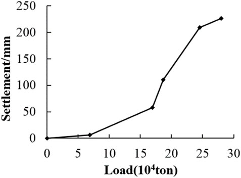
FIGURE 15. Settlement of the open caisson determined by the centrifuge model test.
From Table 3 and Figure 15, the bridge superstructure installation was divided into five steps. The first step is the installation of the lower pylon column. The engineering load was approximately 0.69 million tons, and the corresponding settlement of the caisson foundation was 6.38 mm, which belongs to the slow subsidence stage. The second step was the installation of the middle tower column with a total load of 1.16 million tons and a corresponding settlement of 58.26 mm. The third stage was the installation of the upper pylon with a total load of 1.87 million tons and a corresponding settlement of 110.75 mm. In this stage, the settlement speed of the open caisson increases sharply, which is the fastest stage of subsidence during the entire installation of the bridge superstructure. In the fourth stage of girder installation, the total load reached 2.45 million tons, and the settlement was 209.46 mm, the speed of which was slower than that of upper pylon installation. The last stage was accessory structure installation, in which the load reached the maximum value of 2.80 million tons, the settlement of the open caisson tended to be gentle, and the corresponding settlement was 226.25 mm. The overall settlement of the open caisson gradually increased with increasing load during the bridge superstructure installation. The deformation curve of the open caisson can be roughly divided into three stages of deformation: slowly increasing, rapid, and tending to become stable. From the lower pylon column to middle tower column stage, the deformation was in the slowly increasing stage, while it is in the sharp deformation stage from middle tower installation to girder structure installation; the settlement then tended to become stable from girder structure installation to accessory structure installation.
Figure 16 shows the earth pressure results from the centrifuge model test and the calculation. In Figure 16, the test value is the earth pressure monitored in the middle of the silty clay soil, and the calculation results are computed based on the actual stratum and depth of the silty clay. The comprehensive bulk density of the open caisson was set to 20 kN/m3, and the calculated earth pressure does not consider the influence of stress diffusion from the bottom of the foundation to the silty clay layer. During the superstructure installation period, the soil pressure measured in the middle of the silty clay increased with the increasing load of the bridge superstructure installation. The calculated values generally increased linearly with increasing engineering loads, and the calculated values of the earth pressure were slightly larger than those of the model test, which may be due to stress diffusion not considered in the calculations.
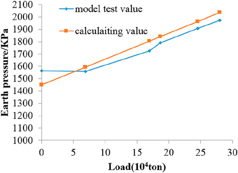
FIGURE 16. Earth pressure results determined by calculation and model test.
Figure 17 shows the settlement curves of the open caisson with the installation of the bridge superstructure calculated by the theoretical layer-wise summation method, the 3D finite element method, and the centrifuge model test. The final settlement was approximately 225 mm when the installation of the bridge superstructure was completed. For the layer-wise summation and finite element methods, the settlements increased linearly with the installation of the bridge superstructure. However, the settlement obtained by the centrifugal model test could be divided into three deformation stages: slowly increasing, rapid, and tending to become stable—these were mainly related to the shear failure characteristics of the soil under the open caisson. By comparing the settlement curves determined by the three methods mentioned previously, it can be seen that the finite element method could simulate the soil characteristics better than layer-wise summation because the former considers the strain hardening characteristics under the vertical load. Furthermore, although there are differences in the settlement of the open caisson during the installation of bridge superstructures, the final settlement values determined by the three methods were consistent.
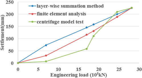
FIGURE 17. Settlements determined by the different approaches during bridge superstructure installation
For the sand layer, the existing studies showed that, with the increase in deviatoric stress, the loose sand gradually becomes dense, and strain hardening occurs, while the dense sand undergoes strain softening after the deviatoric stress reaches its peak value. Whether in loose or dense sand, shear shrinkage occurs under high confining pressure. Strain softening is an unstable process of rearranging and balancing the position of sand particles. In essence, the occlusions between the sand particles are damaged due to the increased stress. The friction strength is more complex in clay soil than in sandy soil. In addition to the sliding and occlusion of the soil particles, the cohesive force of clay has a great influence on its friction strength, which is not only related to the strength of the cementing material but also because it will be strengthened over time. Remolded rather than undisturbed soils were used in the centrifugal model test. Therefore, the shear strength of remolded soil was usually slightly different than undisturbed soil; the older the sedimentary age, the greater is the strength of the undisturbed soil than that of the remolded soil.
According to the actual strata of the caisson foundation in this bridge project, it is sandy soil with a thickness of 7 m under the open caisson, followed by silty clay with a thickness of 12 m. From the settlement curve of the open caisson from the centrifuge test, the deformation characteristics of the soil under the foundation can be described as follows. Before the complete installation of the middle tower column, the soil under the open caisson is further compacted and gradually reaches its peak strength due to the application of the engineering load, which naturally causes the overall settlement to gradually increase with the installation of the middle tower column. During the installation of the middle tower column to the girder structure, the deformation of the soil is characterized by strain softening with increasing deviatoric stress, so the settlement of the caisson foundation presents rapidly increasing characteristics. However, during the installation of the accessory structures, the local soil with shear failure reached a new equilibrium state, and the overall settlement of the caisson foundation tended to become stable under a total engineering load of 0.28 million tons.
1) The settlement deformation of a giant open caisson under the main pier was comprehensively analyzed by a theoretical layer-wise summation method, numerical analysis method, and large centrifuge model test during the construction of the Changtai Yangtze River Bridge. The results demonstrate that the final settlements obtained by three methods were consistent: approximately 225 mm when the bridge superstructure was completely installed.
2) For the theoretical layer-wise summation method, the settlement (544.5 mm) using conventional compression modulus was 2.42 times that of using the compression modulus under actual stress; it is suggested that the compression modulus under the actual stress state of the soil should be utilized rather than under the stress range of 100 kPa
3) The results of the 3D finite element analysis showed that the settlement of the open caisson linearly increased during the installation of the bridge superstructure, and the final settlement was completely consistent with the results of the centrifuge model test. This verified that the HSS constitutive model can reflect the mechanical behavior of the soil in the installation of bridge superstructures.
4) The results of the centrifuge model test demonstrate that the settlement curve of the open caisson can be roughly divided into three deformation stages: slowly increasing, rapid, and tending to become stable. From the lower pylon column to middle tower column stage, the deformation belongs to the slowly increasing stage; it is in the rapid deformation stage from middle tower installation to girder structure installation; the settlement tended to become stable from girder structure installation to accessory structure installation.
The raw data supporting the conclusions of this article will be made available by the authors, without undue reservation.
MG wrote the draft of the manuscript, XD completed the simulation analysis section, and ZY made some contribution to the theoretical analysis.
The authors gratefully acknowledge the financial support of the National Natural Science Foundation of China under Grant No. 51674239.
The authors declare that the research was conducted in the absence of any commercial or financial relationships that could be construed as a potential conflict of interest.
All claims expressed in this article are solely those of the authors and do not necessarily represent those of their affiliated organizations, or those of the publisher, the editors, and the reviewers. Any product that may be evaluated in this article, or claim that may be made by its manufacturer, is not guaranteed or endorsed by the publisher.
Allenby, D., Waley, G., and Kilburn, D. (2009). Examples of open caisson sinking in Scotland. Proc. Inst. Civ. Eng. Geotech. Eng. 162 (1), 59–70. doi:10.1680/geng.2009.162.1.59
Apsel, R. J., and Luco, J. E. (1987). Impedance functions for foundations embedded in a layered medium: an integral equation approach. Earthq. Eng. Struct. Dyn. 15, 213–231. doi:10.1002/eqe.4290150205
Benz, T. (2006). Small strain stiffness of soils and its numerical consequences [D]. Stuttgart: University of Stuttgart.
Bilotta, E., De Sanctis, L., Di Laora, R., D’Onofrio, A., and Silvesti, F. (2015). Importance of seismic site response and soil–structure interaction in dynamic behaviour of a tall building. Géotechnique 65, 391–400. doi:10.1680/geot.sip.15.p.016
Chavda, J. T., Mishra, S., and Dodagoudar, G. R. (2019). Experimental evaluation of ultimate bearing capacity of the cutting edge of an open caisson. Int. J. Phys. Model. Geotechnics 20 (5), 281–294. doi:10.1680/jphmg.18.00052
Chen, S. L., Chen, L. Z., and Pan, E. (2007). Three-dimensional time-harmonic Green’s functions of saturated soil under buried loading. Soil Dyn. Earthq. Eng. 27, 448–462. doi:10.1016/j.soildyn.2006.09.006
Chen, Y., Wen, Z., Jia, P., Han, J., and Guan, Y. (2019). Dynamic behavior of an embedded foundation under horizontal vibration in a poroelastic half-space. Appl. sciences-basel 9, 740. doi:10.3390/app9040740
Cheng, N., and Cassidy, M. J. (2016). Development of a force–resultant model for spudcan footings on loose sand under combined loads. Can. Geotech. J. 53 (12), 2014–2029. doi:10.1139/cgj-2015-0597
Chuanbao, F. (2021). Caisson foundation deformation analysis for north anchorage of Wufengshan Yangtze river bridge. Bridge Constr. 51 (1), 74–81. (in Chinese).
Fan, P. C., and Zhai, C. (2019). HSS ans M-C model analysis of deformation characteristics of subway. Subgr. Eng. 202 (1), 180–183. in Chinese.
Fu, D., Gaudin, C., Bienen, B., Tian, Y., and Cassidy, M. J. (2018). Combined load capacity of a preloaded skirted circular foundation in clay. J. Geotech. Geoenviron. Eng. 144 (11), 4018084. doi:10.1061/(asce)gt.1943-5606.0001960
Guo, M., Dong, X., and Li, J. (2021). Study on the earth pressure during sinking stage of super large caisson foundation. Appl. Sci. 11 (21), 10488. doi:10.3390/app112110488
Hung, L. C., and Kim, S. R. (2014). Evaluation of undrained bearing capacities of bucket foundations under combined loads. Mar. Georesour. Geotechnol. 32 (1), 76–92. doi:10.1080/1064119x.2012.735346
Jiang, B. N., Wang, M. T., Chen, T., Zhang, L. L., and Ma, J. L. (2019). Experimental study on the migration regularity of sand outside a large, deep-water, open caisson during sinking. Ocean. Eng. 193, 106601. doi:10.1016/j.oceaneng.2019.106601
Jin, Z., Yin, Z., Kotronis, P., and Li, Z. (2019). Advanced numerical modelling of caisson foundations in sand to investigate the failure envelope in the H-M-V space. Ocean. Eng. 190, 106394. doi:10.1016/j.oceaneng.2019.106394
Latini, C., and Zania, V. (2017). Dynamic lateral response of suction caissons. Soil Dyn. Earthq. Eng. 100, 59–71. doi:10.1016/j.soildyn.2017.05.020
Li, J. T., Qin, S. Q., and Zhang, R. X. (2020). Developments and prospects of deep-water foundations for bridge. Bridge Constr. 50 (03), 17–24. (in Chinese).
Lian-xiang, L., Jia-dian, L., and Li, K-J. (2019). Study on selection method and applicability of HSS parameters of typical stratum in Jinan[J]. Rock Soil Mech. 40 (10), 4021–4029. (in Chinese).
Mu, B. G., Zhu, J. M., and Gong, W. M. (2015). Design, construction and monitoring of large open caisson. CN: Beijing: China Architecture & Building Press. (in Chinese).
Mu, L., and Huang, M. (2016). Small strain based method for predicting three-dimensional soil displacements induced by braced excavation. Tunn. Undergr. Space Technol. 52 (2), 12–22. doi:10.1016/j.tust.2015.11.001
Nonveiller, E. (1987). Open caissons for deep foundations. J. geotechnical Eng. 113 (5), 424–439. doi:10.1061/(asce)0733-9410(1987)113:5(424)
Park, J., and Park, D. (2017). Vertical bearing capacity of bucket foundation in sand overlying clay. Ocean. Eng. 134, 62–76. doi:10.1016/j.oceaneng.2017.02.015
Park, J., Park, D., and Yoo, J. (2016). Vertical bearing capacity of bucket foundations in sand. Ocean. Eng. 121, 453–461. doi:10.1016/j.oceaneng.2016.05.056
Qin, S. Q., Xu, W., Lu, Q. F., Zheng, Q. G., Fu, Z. G., Yuan, R. A., et al. (2020). Overall design and concept development for main navigational channel bridge of Changtai Changjiang River Bridge. Bridge Constr. 50 (03), 1–10.
Qiu, G., and Henke, S. (2011). Controlled installation of spudcan foundations on loose sand overlying weak clay. Mar. Struct. 24 (4), 528–550. doi:10.1016/j.marstruc.2011.06.005
Royston, R., Sheil, B. B., and Byrne, B. W. (2020). Monitoring the construction of a large-diameter caisson in sand. P. I. Civ. Eng.-Geotec 175 (3), 323–339. doi:10.1680/jgeen.19.00266
Senjuntichai, T., Mani, S., and Rajapakse, R. K. N. D. (2006). Vertical vibration of an embedded rigid foundation in a poroelastic soil. Soil Dyn. Earthq. Eng. 26, 626–636. doi:10.1016/j.soildyn.2006.01.013
Skau, K. S., Chen, Y., and Jostad, H. P. (2018). A numerical study of capacity and stiffness of circular skirted foundations in clay subjected to combined static and cyclic general loading. Geotechnique 68 (3), 205–220. doi:10.1680/jgeot.16.p.092
Templeman, J. O., Phillips, B. M., and Sheil, B. B. (2021). Cutting shoe design for open caissons in sand: influence on vertical bearing capacity. ICE Proc. Geotec. Eng., 1–16. doi:10.1680/jgeen.20.00218
Wang, W-D., Wang, H-R., and Xu, Z-H. (2012). Experimental study of parameters of hardening soil model for numerical analysis of excavations of foundation pits[J]. Rock Soil Mech. 33 (8), 2283–2290. doi:10.16285/j.rsm.2012.08.006
Xia, H., Zhou, X., Zhou, M., Niu, F., and Zhang, X. (2021). Capacity of caissons in stiff-over-soft clay under combined V–H-M loadings. Ocean. Eng. 229 (1), 109007. doi:10.1016/j.oceaneng.2021.109007
Yan, F. Y., and Shi, G. (2013). Analysis of limiting soil resistance beneath cutting curb during sinking of open caisson. Rock Soil Mech. 34 (S1), 80–87. doi:10.16285/j.rsm.2013.s1.063
Zhang, Y., Bienen, B., Cassidy, M. J., and Gourvenec, S. (2011). The undrained bearing capacity of a spudcan foundation under combined loading in soft clay. Mar. Struct. 24 (4), 459–477. doi:10.1016/j.marstruc.2011.06.002
Zhou, H. X., Ma, J. L., Zhang, K., Luo, C. Y., and Yang, B. (2019). Study of sinking resistance of large and deep caisson based on centrifugal model test. Rock Soil Mech. 40 (10), 3969–3976. doi:10.16285/j.rsm.2018.0360
Keywords: open caisson, layer-wise summation method, 3-D finite element analysis, large centrifuge model test, Changtai Yangtze River Bridge
Citation: Guo M, Dong X and Yang Z (2023) Settlement analysis of the giant open caisson during the construction of the Changtai Yangtze River Bridge. Front. Earth Sci. 10:1056695. doi: 10.3389/feart.2022.1056695
Received: 29 September 2022; Accepted: 05 December 2022;
Published: 05 January 2023.
Edited by:
Shibing Huang, Wuhan University of Science and Technology, ChinaReviewed by:
Li Wang, China Three Gorges University, ChinaCopyright © 2023 Guo, Dong and Yang. This is an open-access article distributed under the terms of the Creative Commons Attribution License (CC BY). The use, distribution or reproduction in other forums is permitted, provided the original author(s) and the copyright owner(s) are credited and that the original publication in this journal is cited, in accordance with accepted academic practice. No use, distribution or reproduction is permitted which does not comply with these terms.
*Correspondence: Mingwei Guo, bXdndW9Ad2hyc20uYWMuY24=
Disclaimer: All claims expressed in this article are solely those of the authors and do not necessarily represent those of their affiliated organizations, or those of the publisher, the editors and the reviewers. Any product that may be evaluated in this article or claim that may be made by its manufacturer is not guaranteed or endorsed by the publisher.
Research integrity at Frontiers
Learn more about the work of our research integrity team to safeguard the quality of each article we publish.