 Yalong Jiang
 Jianjun Zeng2
94% of researchers rate our articles as excellent or good
Learn more about the work of our research integrity team to safeguard the quality of each article we publish.
Find out more
ORIGINAL RESEARCH article
Front. Earth Sci., 10 January 2023
Sec. Geohazards and Georisks
Volume 10 - 2022 | https://doi.org/10.3389/feart.2022.1047484
In order to improve the digging efficiency of tunnel boring machine (TBM) in high-strength and highly abrasive formations, high-pressure water jet-assisted tunnel boring machine rock breaking technology has been developed and applied in steps. In this study, rock breaking mechanism by the new technology is investigated based on two-dimensional particle flow code (PFC2D) modelling. The force chain field distribution law and crack extension evolution characteristics of three typical rock breaking models are studied, and the influence of precutting slits parameters on force chain field distribution, rock sample rupture pattern, and peak load are further analysed. The results show that: 1) The rock breaking processes of the three typical modelling types (i.e., complete cutting model, same trajectory cutting model, and different trajectory cutting model) are different. Among them, the different trajectory cutting model is more likely to produce tensile failure and effectively reduce the penetration depth required for rock breaking. 2) The percentages of tension cracks to the total cracks in the three typical modellings are 90.8%, 93.9%, and 89.8%, respectively, indicating that the above three models are dominated by tension damage in the mesoscopic view. 3) With the increase of the depth of the precutting slit, the depth of the stress concentration zone beneath the disc cutter increases, inducing the increase of the angle between the edge of the stress concentration zone and the upper surface of the rock sample. Meanwhile, the peak load decreases, hence the difficulty of the tunnel boring machine disc cutter penetration is gradually reduced.
Tunnel boring machine (TBM) are widely used in highway tunnels and water conservancy tunnels because of their characteristics of high speed, safe operation, high degree of automation and friendly operating environment (Huo et al., 2011; Yin et al., 2016; Liu et al., 2020). The TBM disc cutter is located at the front edge of the shield cutterhead and is in direct contact with the surrounding rock, which is subject to strong thrust, high torque, and sudden impact loads during the rock breaking process (Ates et al., 2014). Therefore, it is essential to investigate the disc cutter’s rock breaking mechanism in order to extend the service life of disc cutters and assure the safe and efficient tunneling of TBMs (Zhang et al., 2022).
For investigations on the mechanics of rock breaking by disc cutters, experimental and numerical simulation methods are more intuitive (Marji et al., 2009; Tumac and Balci, 2015; Pan et al., 2018; Bi et al., 2020). Snowdon et al., 1982 studied the destruction process of sedimentary rocks and granite using linear cutting tests, and optimized the ratio of disc cutter spacing to cutting depth. Rosutami, 1993 used indoor linear cutting tests to investigate the formation mechanism of rock slices between double disc cutters, and predict the effect of TBM excavation under different conditions. Innaurato et al. (2007) conducted single-disc cutter rock breaking tests in granite and limestone under unconfined and lateral limiting conditions, and analyzed the effects of rock type, rock size, and confining pressure on rock breaking by TBM disc cutters. However, there are still numerous difficulties in revealing the rock breaking mechanism through large-scale indoor experiments or in-situ tests due to high economic cost and operational complexities (Jing, 2003). With the rapid development of computer technologies and numerical computation methods, numerical simulation has become an increasingly important research tool in the field of rock mechanics. Huang et al. (1998) used FLAC3D software based on finite difference scheme to investigate the rock breaking mechanism and rock breaking efficiency of wedge-shaped TBM disc cutters under the action of confining pressure. Mohammad et al. (2009) simulated the rock breaking process of TBM disc cutters based on a higher order displacement discontinuity method developed by boundary element (BEM), and performed a predictive analysis of the crack emergence angle and expansion path. Li et al. (2016) investigated the mesoscopic mechanical mechanism of rock breaking through wedge-shaped disc cutters by introducing a cluster particle model in PFC2D software, and comparing the simulation results with indoor tests. Zhang et al. (2018, 2020) established two-dimensional and three-dimensional numerical models of rock breaking by disc cutters, respectively, and investigated the influence law of joints and soft-hard rock formations on the rock breaking process.
The above research achievements provide guidance for cutter type selection, cutterhead layout optimization, and tunnelling parameter adjustment during TBM digging in conventional strata (Zhang et al., 2021). However, with the growing demand for transportation infrastructure and deep resource extraction, a large number of deep buried long tunnels have emerged, and TBM tunnelling has encountered new challenges. For instance, once high-strength and highly abrasive hard rock strata is encountered during TBM tunneling process, typical engineering problems will inevitably be induced, such as difficulty in TBM boring, severe tool wear, and damage to cutter bearings (Yagiz, 2008; Zhang et al., 2010; Tóth et al., 2013), as shown in Figure 1, which significantly affect the construction schedule and budget. Usually, reasonable optimization of the cutterhead layout (e.g., disc cutter spacing, easy to wear parts configuration, etc.) (Huo et al., 2011) and tool parameters (e.g., cutter size, blade type, wear resistance, etc.) (Geng et al., 2015), adjustment of boring parameters (e.g., cutter thrust, rotational speed, and penetration rate, etc.) (Gharahbagh et al., 2014) are conducted to achieve lower tool wear and higher digging efficiency. However, for high-strength and highly abrasive strata, it is difficult to achieve a qualitative breakthrough in terms of tunnelling efficiency and construction cost just through adjustment and optimization of the aforementioned parameters.

FIGURE 1. TBM disc cutter damage (A) disc cutter offset grinding (B) cutter ring collapse (C) cutter ring curling edge (D) bearing damage.
To improve the TBM rock breaking efficiency in high-strength and highly abrasive strata and reduce the digging cost, researchers have explored numerous new rock breaking methods, among which high-pressure water jet-assisted rock breaking technology has attracted widespread research interest with its advantages of high efficiency and cleanliness (Ciccu and Grosso, 2010; 2014; Bilgin et al., 2012). At present, the high-pressure water jet-assisted rock breaking technology has been successfully applied in practical engineering. In June 2019, the first high-pressure water jet-assisted TBM, named “Longyan”, was designed and manufactured by the China Railway Engineering Equipment Group and Yellow River Design Institute in China (Cheng et al., 2021), as show in Figure 2. This new TBM has been used in Wan-anxi headrace tunnel excavation in Fujian Province, which further promotes research on high-pressure water jet-assisted rock breaking techniques. Currently, scholars in China and around the world have conducted some research on high-pressure water jet-assisted TBM disc cutters rock breaking, and there have been a number of breakthroughs. For example, Tang et al. (2013) developed an abrasive water jet-assisted rock breaking bit, using the combination of an abrasive water jet ejected from the middle of the bit and external cutter teeth to cut hard rock, and discovered that the digging speed was significantly increased and the wear of the bit was significantly reduced. Ciccu and Grosso, 2014 experimentally analyzed the rock breaking performance of medium-strength rock samples under the combined action based on a self-designed water jet-assisted rock breaking system; Liu et al. (2020) studied water jet groove-assisted disc cutters to break hard rock, and the results showed that water jet groove-assisted rock breaking technology can significantly improve the rock breaking performance of the tool; Karakurt et al., 2014 used abrasive water jet-assisted in cutting granite samples, and obtained the effects of abrasive concentration and nozzle distance on the precutting slit width; Wang et al. (2020) used the FEM-SPH coupling method to study and analyze the tool force state and the optimization of water jet parameters during high-pressure water jet-assisted TBM disc cutters rock breaking process. Based on 3DEC numerical simulation combined with indoor quasi-static penetration test; Cheng et al. (2020; 2021) investigated the internal and surface crack extension mechanism of TBM disc cutters under the action of high-pressure water jet slitting, and explored the influence of confining pressure on the rock breaking process. Li et al. (2013) investigated the rock breaking technology of precutting groove assisted disc cutter based on PFC2D, and the mechanism and law of rock breaking with different precutting groove assisted methods were revealed.
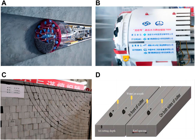
FIGURE 2. High-pressure water jet assisted TBM rock break technique. (A) feed-water circuit (B) high pressure water jet (C) cutting trajectory in rock samples induced by high pressure water jet (D) layout model of water jet and disc cutter (Cheng et al., 2020).
It can be concluded that the existing research mainly focuses on the conventional TBM rock fragmentation mechanism, still little is known about the rock breaking mechanism of high-pressure water jet-assisted TBM digging technique, particularly the stress field distribution of rock samples and the influence of precutting slit parameters under various breaking modes. In this study, numerical modellings are established by PFC2D to investigate the stress field distribution and crack extension evolution characteristics of three typical rock breaking models. Further analysis is conducted to explore the influence of precutting slit parameters on the force chain field distribution, rock sample fracture pattern, and peak load. On this basis, the failure modes and penetration damage mechanisms of high-pressure water jet-assisted TBM digging technique is discussed.
In this paper, the PFC2D software is used to establish the relevant rock model, and the rock material is characterized by the aggregation of circular particles. According to previous literatures (Hazzard et al., 2000; Chang et al., 2002; Tian et al., 2018; Yao et al., 2019), the particle radius used in various granite modellings are mainly concentrated between 0.25 mm and 0.75 mm. With a combined consideration of simulation accuracy and calculation efficiency, the particle radius is set as 0.5 mm–0.75 mm in this study. A linear parallel bond is applied between adjacent particles to simulate the adhesion between rock particles, so that the contact part of the particles has certain elastic properties and the ability to resist tension, shear, and torsion, thus making the model present macroscopic mechanical properties similar to the actual rock.
In this study, granite samples cored from Macheng city, Hubei Province, are used. Some basic tests, including uniaxial compression tests and Brazilian splitting tests, are conducted to obtain the uniaxial compressive strength (UCS), Young’s modulus, Poisson’s ratio, and Brazilian tensile strength (BTS) of the samples according to the International Society of Rock Mechanics (ISRM) standard (Jiang et al., 2022). Firstly, numerical uniaxial compression and Brazilian splitting tests are conducted through PFC2D modellings to calibrate the mesoscopic parameters according to the laboratory test results. The loading rate is set as 0.02 m/s and the time step is set to 6×10⁻⁸ s to achieve a quasi-static loading state (Li et al., 2016). The " trial-and-error method " is used to calibrate the mesoscopic parameters of the rock sample until the developed model can well replicate the physical and mechanical properties of the target rock samples (Lee and Jeon, 2011). From the calibration procedure, the rock mesoscopic parameters are determined (as shown in Table 1). Simulations using this set of parameters are performed to get simulation and test results of uniaxial compression test and Brazilian splitting test, as shown in Figure 3, where dark green represents tensile cracks and pink represents shear cracks. The macroscopic mechanical parameters of the rock are listed in Table 2.
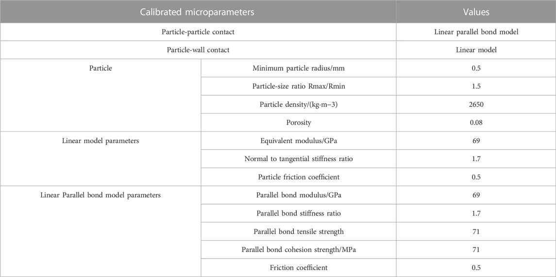
TABLE 1. Mesoscopic parameters of rocks.
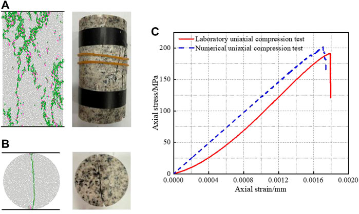
FIGURE 3. Comparison of indoor test and simulation results (A). Uniaxial compression test (B). Brazilian splitting test (C). Axial stress-strain curve of uniaxial compression test.
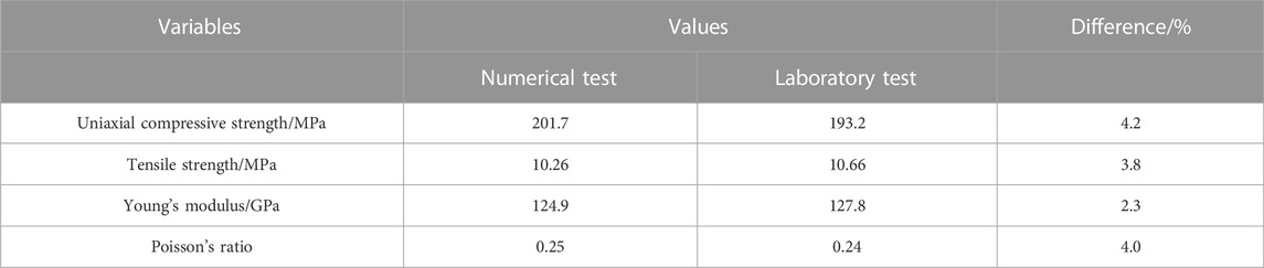
TABLE 2. Macroscopic parameters of rocks.
As shown in Table 2, the results of the macroscopic parameters of the rocks obtained from the numerical simulations are in good agreement with the experimental results, in which the errors of uniaxial compressive strength, tensile strength, elastic modulus, Poisson’s ratio are within 5%. Figures 3A, B indicate that the model failure patterns derived from the numerical tests of uniaxial compression and Brazilian splitting correlate well with the indoor test findings. Figure 3C demonstrates that the model axial stress-strain curve evolution pattern derived from uniaxial compression numerical tests is more consistent with the experimental results, and the peak intensity generated from the simulation has a relatively small error (4.2%). However, the discrete element model used in this paper does not consider the influence of initial micro-cracks in the rock sample. As a result, the uniaxial compression axial stress-strain curve obtained from the numerical simulation cannot capture the compression-density phase due to the initial crack closure (Ji et al., 2018; Wang et al., 2021; Ye et al., 2022). Overall, the model replicates the macroscopic mechanical properties and deformation and failure behavior features of granite samples more accurately, its mesoscopic mechanical parameters (see Table 1) are valid, and may be employed in subsequent numerical simulations of TBM disc cutters penetration tests.
Figure 4A Depicts the numerical model of TBM disc cutter penetration,Which is composed mostly of the complete cutting model, the same trajectory cutting model, and the difference trajectory cutting model. The same trajectory cutting model refers to the high-pressure water jet precutting slit located directly beneath the disc cutter, as shown in Figure 4B. In the actual working condition, it represents the working condition in which the high-pressure water jet nozzle and disc cutter are arranged on the same cutting radius, and overlap of the leading water jet precutting trajectory and the later TBM disc cutter trajectory (Xu et al., 2022). The different trajectory cutting model refers to the high-pressure water jet precutting slit located at the side of the disc cutter, and the distance L exists between the precutting slit and the tool axis, as shown in Figure 4C. In the actual working condition, it represents the situation where the cutting trajectory of the water jet is not overlapping with the cutting trajectory of the TBM disc cutter (Xu et al., 2022). In this study, the width and height of the rock sample are set to 190 mm and 150 mm, respectively, and the model consisted of about 21,000 particles. At present, the diameter of high-pressure water jet nozzle is mainly 1.02 mm, and the width of precutting slit is about 2 mm when cutting hard rock under certain pressure conditions (Cheng et al., 2021; Bi et al., 2022; Jiang et al., 2022; Li et al., 2022). The previous literatures demonstrate the feasibility of using 2 mm precutting slit width in the experiments. Therefore, in this manuscript, the width of the precutting slit is set as 2 mm. On the basis of the complete cutting model, a 2 mm width is used to delete particles at a specific location as the high-pressure water jet precutting slits (Cheng el al., 2022), while the precutting slits depth H is taken as 10 mm, 20 mm, 30 mm, and 40 mm, and the precutting slit-tool axis distance L is taken as 10 mm, 20 mm, 30 mm, 35 mm, 40 mm, and 50 mm, respectively. The disc cutter is simplified to an infinitely rigid wall with a blade width of 2 mm. The initial position of the cutter is 0.1 mm from the upper surface of the rock sample, the disc cutter penetration speed is 0.01 m/s, the time step is 3.6×10⁻⁷, and the disc cutter penetration speed is converted to 3.6×10⁻⁹ m/s to ensure that the simulation is in a quasi-static equilibrium loading state (Li et al., 2016). The maximum vertical penetration depth of the disc cutter is set to 5 mm.
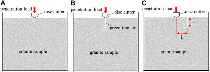
FIGURE 4. TBM disc cutters breaking model (A) complete cutting model (B) same trajectory cutting model (C) different trajectory cutting model.
In order to compare the crack evolution process under different rock breaking models, three groups of rock breaking models are established: the complete cutting model, the same trajectory cutting model with a precutting slit depth H of 20 mm. Based on previous research work, the TBM disc cutter spacing for hard rock conditions is usually in the range of 60 mm–90 mm (Zhai et al., 2016; 2017; Zhou et al., 2018; 2020; Li et al., 2022). This manuscript mainly considers the situation where the high-pressure water jet nozzle is located in the middle of the two adjacent disc cutters in the different trajectory cutting model. Therefore, the precutting slit-tool axis spacing is set as 35 mm. The maximum penetration depth of the cutter for all three groups is 5 mm.
Figure 5 shows the failure evolution process of the disc cutter penetration into the complete cutting model. As shown in Figure 5A, when the disc cutter is just in contact with the rock sample, a significant stress concentration zone (dark black region) emerges right beneath the disc cutter, which is composed primarily of compressive stress. As shown in Figure 5B, with the further penetration of the disc cutter, tensile stresses are concentrated beneath the disc cutter and micro-cracks are generated, which converge to form a significant damage area, called the powder core area, which is highly damaged by micro-cracks, resulting in crushed rock slag beneath the TBM disc cutter (Xue et al., 2021). As shown in Figure 5C, as the penetration depth of the disc cutter continues to increases, the stress concentration zone expands to the deeper part due to the force transferring effect of the powder core area, and the micro-cracks beneath the disc cutter continue to develop and extend to produce lateral tensile cracks. As shown in Figure 5D, when the penetration depth reaches 5 mm, the tensile crack on the left side of the disc cutter further expands and part of the tensile crack penetrates the upper surface of the rock sample, forming a tiny rock slag. Observing the whole rock breaking process, the powder core area formed beneath the disc cutter keeps expanding, and the lateral cracks keep extending, but no larger rock slag is formed.
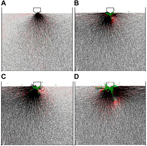
FIGURE 5. Simulation of the failure evolution of the complete cutting model (A) 0.1 mm (B) 2.5 mm (C) 3.6 mm (D) 5 mm (black for compression/red for tension, dark green for tensile cracking/pink for shear cracking).
Figure 6 shows the failure evolution process of the disc cutter penetration into the same trajectory cutting model. As shown in Figure 6A, when the TBM disc cutter acts directly above the precutting slit, there is a significant compressive stress concentration zone on the left side of the precutting slit, while tensile stress is generated on the right side of the precutting slit, but the concentration degree of tensile stress is low, and no micro-cracks generates at this time. As shown in Figure 6B, with the further penetration of the TBM disc cutter, the rock walls on both sides of the precutting slit produce micro-cracks due to the extrusion of the disc cutter, causing the rock wall failures and falls off. In addition, since the disc cutter keeps repeating the process of squeezing the rock wall-rock wall spalling-further penetration of the disc cutter-squeezing the rock wall again along the precutting slit, the tensile stress concentration phenomenon occurs at the bottom of the precutting slit. As shown in Figure 6C, as the penetration depth of the disc cutter continues to increases, the tensile stress concentration zone moves downward, and the rock sample is split and tensioned to generate the main crack that grows downward from the bottom of the precutting slits. As shown in Figure 6D, when the main crack develops a particular depth and ceases to extend downward, a lateral crack propagated in nearly horizontal direction is generated beneath the disc cutter, and it penetrates the upper surface of the rock sample, forming a rock fragment. Observing the whole rock breaking process, it is indicated that the same trajectory cutting model generates a tensile stress concentration zone at the bottom of the precutting slit due to the wedge cracking effect of the disc cutter (Li et al., 2022). This effect causes cracks to develop in the vertical direction, followed by the penetration of lateral cracks into the upper surface of the rock sample to form rock fragments.
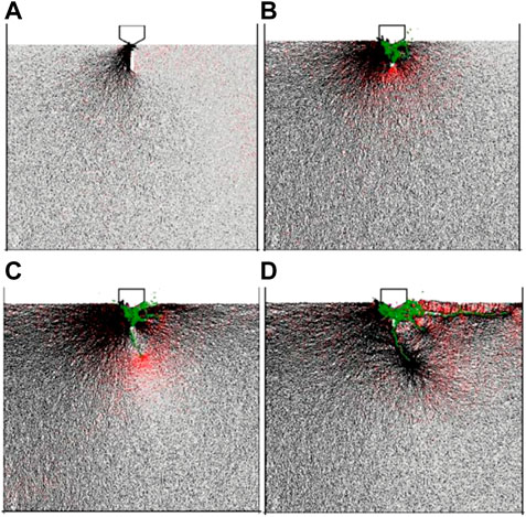
FIGURE 6. Simulation of the failure evolution process of the same trajectory cutting model (A) 0.1 mm (B) 2.5 mm (C) 3.6 mm (D) 5 mm.
Figure 7 shows the failure evolution process of the disc cutter penetration into the different trajectory cutting model. As shown in Figure 7A, when the disc cutter is just in contact with the rock sample, consistent with the complete cutting model, the different trajectory cutting model also produces a significant stress concentration zone dominated by compressive stresses, but the angle between the edge of the stress concentration zone and the upper surface of the rock sample is greater in the different trajectory model. As shown in Figure 7B and Figure 7C, with further penetration of the disc cutter, a vertical downward main crack is generated beneath the disc cutter. After the main crack is generated, the internal stresses of the rock sample are adjusted, and the tensile stress concentration phenomenon appears at the bottom of the precutting slits. A lateral crack is generated beneath the disc cutter and coalesces with the bottom of the precutting slits, forming a triangular rock chip and an effective rock breaking process is completed. At this point, the penetration depth of the disc cutter is still relatively small (0.20 mm), indicating that the high-pressure water jet-assisted TBM disc cutter can reduce the penetration depth required for rock breaking to a greater extent by using a different trajectory arrangement. As shown in Figure 7D, after the formation of the triangular rock chip, as the penetration depth of the disc cutter continues to increases, the powder core area gradually increases to produce more crushed rock slag. The above analysis demonstrates that the rock breaking process of the different trajectory cutting model differs significantly from the complete cutting model and the same trajectory cutting model, primarily because the different trajectory cutting model can induce the development of lateral cracks toward the bottom of the precutting slit, which makes the rock more prone to tensile failure and effectively reduces the penetration depth required for rock breaking.
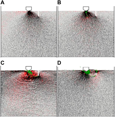
FIGURE 7. Simulation of the failure evolution process of different trajectory cutting models (A) 0.1 mm (B) 0.15 mm (C) 0.2 mm (D) 5 mm.
In order to analyze the evolution process of internal cracks under the action of TBM disc cutters in different rock breaking models, this study records the type and number of micro-cracks generated during the disc cutter penetration process through the Fish function.
Figure 8 depicts the evolution of the number of micro-cracks for the three rock breaking models. It can be seen that the micro-cracks keep growing during the process of TBM disc cutter penetration into the rock sample, the micro-cracks do not grow smoothly, but show a " flat-steep-increase-flat-steep-increase " change pattern, which has a certain correlation with the leapfrog failure of the rock. This is because in the process of rock breaking by the disc cutter, when there are rock fragments falling off, the thrust of the disc cutter decreases and the number of cracks tends to level off, while when the thrust increases, the number of cracks will increase accordingly. Tensile cracks and shear cracks appear simultaneously in all models, but the number of tensile cracks is significantly higher than that of shear cracks.
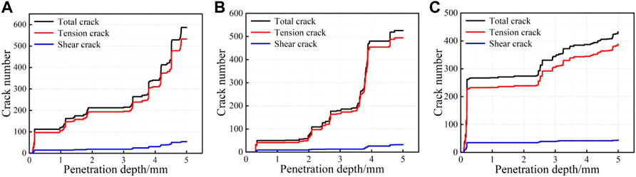
FIGURE 8. Micro-crack evolution curve (A) complete cutting model (B) same trajectory cutting model (C) different trajectory cutting model.
For the complete cutting model, the number of cracks grows slowly before the penetration depth of 3 mm, and after the penetration depth of 3 mm, the tensile cracks show several consecutive and significant increases, as shown in Figure 8A. This is due to the sprouting and expansion of the main cracks and lateral cracks in the complete rock sample. For the same trajectory cutting model, a sudden increase in the number of cracks occurs at the penetration depth of about 3.5 mm, from 191 to 480, as shown in Figure 8B, reflecting the characteristic of the brittle damage of rock materials. Compared with the complete cutting model and the same trajectory cutting model, the different trajectory cutting model has a sudden increase at the penetration depth of 0.20 mm, as shown in Figure 8C. This is mainly due to the coalescence of the lateral crack beneath the disc cutter with the bottom of the precutting slits. The penetration depth corresponding to the sudden increase is greatly reduced compared with other two rock breaking models, indicating that the different trajectory cutting model can greatly reduce the penetration depth required for rock breaking (Li et al., 2022).
Figure 9 shows the histograms of the percentage of tensile and shear cracks for different rock breaking models. As can be seen from the figure, the percentage of tensile cracks to total cracks being 90.8%, 93.9%, and 89.0%, respectively, for the complete cutting model, the same trajectory cutting model, and the different trajectory cutting model. This phenomenon shows that the above three rock breaking models are dominated by tensile failure and supplemented by shear failure in the mesoscopic.
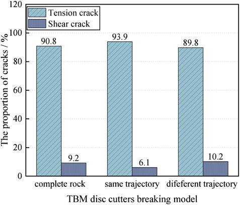
FIGURE 9. Percentage of cracks under different rock breaking models.
From the force chain field and micro-crack evolution process of the above three rock breaking models it can be found that when the disc cutter is just in contact with the rock sample, the stress concentration zone is dominated by compressive stress. As the disc cutter penetration depth continues to increases, the stress concentration zone expands to the deeper part and both sides. With the further penetration of the disc cutter, the concentration degree of tensile stress inside the rock increases, tensile cracks are easily generated in the tensile stress concentration zone, and the tensile cracks are expanding in the process of transferring the tensile stress concentration zone. Among them, the complete rock sample first generates a powder core area under the action of the disc cutter, then generates lateral cracks to penetrate upper surface of the rock sample and form rock slags. When the disc cutter trace overlaps with the precutting slit, due to the wedge cracking effect of the disc cutter, the tensile stress concentration at the bottom of the precutting slit and induce the micro-crack to develop in the vertical downward direction to form the main crack, then a lateral crack propagated in nearly horizontal direction is generated beneath the disc cutter, and it penetrates the upper surface of the rock sample, forming a rock fragment. When the disc cutter trace does not overlap with the precutting slit and is 35 mm apart, the tensile stress at the bottom of the pre-cutting slit concentrates and induces the lateral cracks to develop toward the bottom of the precutting slit, resulting in the formation of larger triangular rock chip and an effective rock breaking process. For micro-crack evolution, tensile cracks and shear cracks appear simultaneously in the three models, but the number of tensile cracks is significantly greater than the number of shear cracks. Moreover, the percentages of tension cracks to the total cracks in the three typical modellings are 90.8%, 93.9%, and 89.8%, respectively, indicating that the above three rock breaking models are dominated by tensile failure and supplemented by shear failure in the mesoscopic.
Figure 10 shows the distribution of the internal force chain field of the rock under various precutting slit parameters. It can be found that when the disc cutter is in contact with the rock sample, a stress concentration zone with mainly compressive stress will be generated beneath the disc cutter, and the farther away from the disc cutter, the smaller the degree of stress concentration, and the stress transfer to the position of the precutting slit is blocked, which is caused by the decompression effect of the precutting slit (Tan et al., 2012). As can be seen from the figure, due to the effect of the precutting slit tip, the bottom of the precutting slit also distributes the relative stress concentration zone (Wang et al., 2020), and the stress concentration zone tends to develop along the bottom of the precutting slit from beneath the disc cutter. Therefore, it appears that the stress concentration degree beneath the disc cutter is high on the precutting slit side and low on the non-precutting slit side, which is most significant when the precutting slit depth H is 30 mm and 40 mm. And as the precutting slit depth increases, the depth of the stress concentration zone beneath the disc cutter increases, and the angle between the edge of the stress concentration zone and the upper surface of the rock sample also increases.
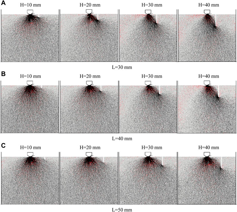
FIGURE 10. Distribution of force chain field with different precutting slit parameters. (A) L = 30 mm, (B) L = 40 mm, (C) L = 50 mm
By studying the effect of the precutting slit-tool axis spacing on the force chain field beneath the TBM disc cutter, it is found that when the precutting slit depth H is 10 mm and 20 mm, the stress concentration zone beneath the disc cutter does not change as the precutting slit-tool axis spacing increases. This indicates that the precutting slit-tool axis spacing has little effect on the stress concentration zone beneath the disc cutter under the small precutting slit depth condition. When the precutting slit depth H is 30 mm and 40 mm, with the increase of precutting slit-tool axis spacing, the stress concentration zone beneath the disc cutter expands to both sides, and the concentration degree of tensile stress in the stress concentration zone gradually increases. This is mainly due to that with the increase of precutting slit-tool axis spacing, the stress concentration zone to precutting slit bottom development extension path increases, and then the stress concentration zone expansion range increases. It is shown that the influence law of precutting slit-tool axis spacing on stress concentration zone is related to the depth of precutting slit, and the influence law varies with precutting slit depth.
Figure 11 depicts a summary of the rock sample rupture patterns with different precutting slit parameters, from which it can be found that, except for the rock samples with precutting parameters of L=50 mm and H=10 mm (as shown in Figure 11 (e1)), the rock sample rupture patterns is caused by the cracks beneath the disc cutter penetrating the precutting slits. This is due to the presence of the precutting slit modifies the original boundary constraint, which weakens the ability of the original rock to resist crushing, and provides a crack cut-off surface to block the extension and expansion of some cracks beneath the disc cutter, thereby causing the cracks beneath the disc cutter to penetrate the precutting slit. The rock sample rupture pattern is consistent with the previous laboratory penetration test result (Jiang et al., 2022), as shown in Figure 12, which fully demonstrates that the precutting slits can change the crack extension direction and determine the final shape of the rock chipping.
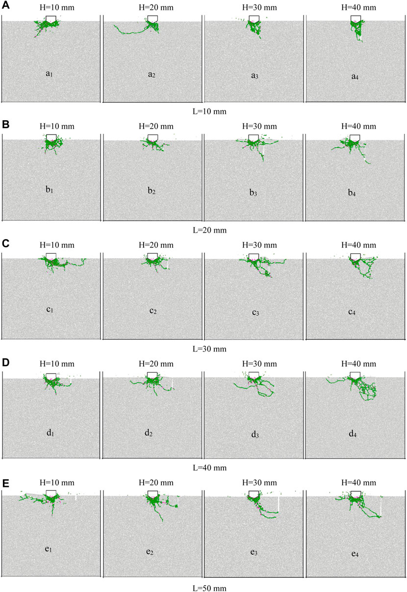
FIGURE 11. (A) L=10 mm, (B) L=20 mm, (C) L=30 mm (D) L=40 mm (E) L=50 mm.
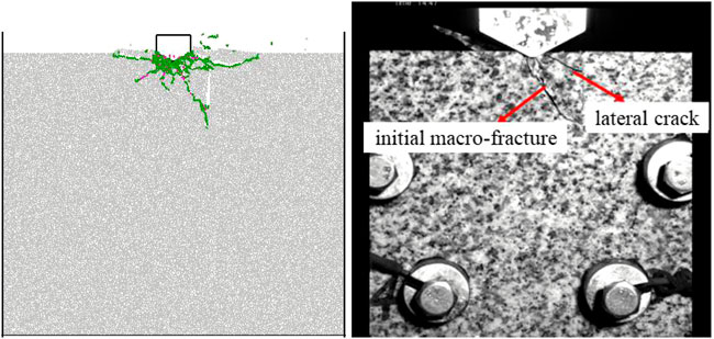
FIGURE 12. Rock sample destruction diagram (L=20 mm H=30 mm).
From Figure 11A and Figure 11B, it can be seen that when L is 10 mm and 20 mm, the cracks beneath the disc cutter penetrates with the bottom of the precutting slit to form triangular rock chip first. With further penetration of the disc cutter, the triangular rock chips are further broken to form smaller rock fragments and crushed rock slags, especially when the precutting slit depth H is 10 mm (as shown in Figure 11(a1) and Figure 11(b1)), the triangular rock chip are over-crushed completely into crushed rock slags. As shown in Figure 11C; Figure 11D, when L is 30 mm and 40 mm, the cracks beneath the disc cutter are directly connected with the bottom of the precutting slit, producing a relatively large volume of triangular rock chip, some rock samples produce lateral cracks to the left and through with the upper surface of the rock samples, further facilitating rock breaking. As shown in Figure 11E, when L is 50 mm, the main cracks are firstly produced to extend downward, and only when the disc cutter penetrates a certain depth, the lateral cracks are produced to penetrate with the bottom of the precutting slit. It should be further noted that when the precutting slits depth H is too small, the crack beneath the disc cutter does not penetrate the precutting slit (as shown in Figure 11(e1)). As shown in Figure 11, the depth of the precutting slit affects the penetration crack angle (angle with horizontal direction), and the greater the depth of the precutting slit, the greater the penetration crack angle and the volume of the triangular rock chip generated.
H=10 mm H=20 mm H=30 mm H=40 mm.
1) L=10 mm
2) L=20 mm
3) L=30 mm
4) L=40 mm
5) L=50 mm
Figure 13 shows the graphs of peak load variation of rock samples with different precutting slit parameters. As shown in Figure 13A, with the same confining pressure, as the precutting slit depth increases, the peak load of the disc cutter for each precutting slit-tool axis spacing condition has an obvious reduce trend. This is due to the existence of the precutting slit to release the lateral constraint inside the rock, the greater the depth of the precutting slit, the larger the lateral constraint release area in its vicinity, the more obvious stress release, the reduction of rock breaking resistance, so the peak load shows a lower trend. The trend indicates that as the depth of the precutting slit increases, the difficulty of penetrating the rock sample by the TBM disc cutter is gradually reduced. However, once the precutting slit depth reaches 30 mm, the trend of decreasing peak load as the precutting slit depth increases is no longer significant, indicating that there is a critical precutting slit depth for high-pressure water jet-assisted TBM disc cutter rock breaking beyond which the effect of increasing precutting slit depth on peak load will be diminished. As shown in Figure 13B, the peak load increases as the precutting slit-tool axis spacing increases. This is because as the spacing increases, the path between the crack beneath the disc cutter and the bottom of the precutting slit increases, thereby increasing the energy required to break the rock, which in turn increases the peak load. It is shown that the difficulty of penetrating the rock sample with the TBM disc cutters increases gradually as the precutting slit-tool axis spacing increases (Cheng et al., 2022).
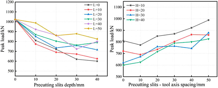
FIGURE 13. Variation curve of peak load of rock samples with different precutting slit parameters. (A) Precutting slits depth (B) Precutting slits—tool axis spacing.
In this paper, a numerical model of TBM disc cutters penetration is established by PFC2D to investigate the stress field distribution and crack extension evolution characteristics of three typical rock breaking models. The influence of precutting slit parameters on force chain field distribution, rock sample fracture pattern and peak load is further analyzed, and the following main conclusions are drawn:
1) Significant differences are found in the rock breaking processes of the three typical models. The complete rock sample first generates a powder core area under the action of the disc cutter, and then generates lateral cracks to penetrate the upper surface of the rock sample and form fine rock slags. When the disc cutters trace overlaps with the precutting slit, the main crack develops in the vertical direction due to the wedge cracking effect of the disc cutter, and then the lateral cracks penetrate the upper surface of the rock sample to form rock fragments. When the disc cutters trace does not overlap with the precutting slit, the tensile stress at the bottom of the pre-cutting slit concentrates and induces the lateral cracks to develop toward the bottom of the precutting slit, resulting in the formation of larger triangular rock chip and an effective rock breaking cycle.
2) From the micro-crack evolution process, it is found that tensile cracks and shear cracks appear almost simultaneously in the three models. However, the number of tensile cracks is significantly greater than that of shear cracks. The percentages of tension cracks to the total cracks in the three typical modellings are 90.8%, 93.9%, and 89.8%, respectively, indicating that all three rock breaking models of rock breaking are dominated by tensile failure and supplemented by shear failure.
3) As the depth of the precutting slit increases, the depth of the stress concentration zone beneath the disc cutter increases, and the angle between the edge of the stress concentration zone and the upper surface of the rock sample also increases. This causes an increase in the propagation angle of the penetration crack when the rock sample is damaged as well as the volume of the triangular rock chip formed by the coalescence of the lateral crack and the bottom of the precutting slit. As the depth of the precutting slit increases, a significant decrease trend in the peak load is observed, indicating a decrease in TBM cutter penetration difficulty.
4) The influence of precutting slit-tool axis spacing on stress concentration area and rock sample failure pattern is related to the depth of precutting slit. However, when the spacing increases, the peak load exhibits an upward trend, indicating that the TBM cutter penetration difficulty is gradually rising.
However, there are still some limitations to this research work, and further investigations are needed. For example, the cutting effect of the high-pressure water jet is modeled as smooth and flat vertical precutting slits on the rock surface, which differs from the actual engineering situation (Jiang et al., 2022). In addition, this study only discusses part of the cutting conditions and does not consider the energy required for water jet precutting (Li et al., 2022). Furthermore, the influence of other main factors, such as cutter type and rock type, on the rock breaking mechanism assisted by high-pressure water jet needs to be further studied.
The original contributions presented in the study are included in the article/supplementary material, further inquiries can be directed to the corresponding author.
YJ, JZ, LJ, and CX are the main accomplishers of this research, jointly completed the numerical simulation part. FX provided assistance in date acquisition and processing.
The research work is supported by the State Key Laboratory of Performance Monitoring and Protecting of Rail Transit Infrastructure Foundation (No. HJGZ2021102), the National Natural Science Foundation of China (42267022), and the Natural Science Foundation of Jiangxi Province (20212BAB204012).
Author LJ was employed by the Company China Railway Engineering Equipment Group Co.,Ltd.
The remaining authors declare that the research was conducted in the absence of any commercial or financial relationships that could be construed as a potential conflict of interest.
All claims expressed in this article are solely those of the authors and do not necessarily represent those of their affiliated organizations, or those of the publisher, the editors and the reviewers. Any product that may be evaluated in this article, or claim that may be made by its manufacturer, is not guaranteed or endorsed by the publisher.
Ates, U., Bilgin, N., and Copur, H. (2014). Estimating torque, thrust and other design parameters of different type TBMs with some criticism to TBMs used in Turkish tunneling projects. Tunn. Undergr. Space Technol. 40, 46–63. doi:10.1016/j.tust.2013.09.004
Bi, J., Liu, P. F., and Gan, F. (2020). Effects of the cooling treatment on the dynamic behavior of ordinary concrete exposed to high temperatures. Constr. Build. Mater. 248, 118688. doi:10.1016/j.conbuildmat.2020.118688
Bi, J., Tang, J. C., Wang, C. L., Quan, D. G., and Teng, M. Y. (2022). Crack coalescence behavior of rock-like specimens containing two circular embedded flaws. Lithosphere, 2022. (Special 11). doi:10.2113/2022/9498148
Bilgin, N., Copur, H., and Balci, C. (2012). Effect of replacing disc cutters with chisel tools on performance of a TBM in difficult ground conditions. Tunn. Undergr. space Technol. 27 (1), 41–51. doi:10.1016/j.tust.2011.06.006
Chang, S. H., Yun, K. J., and Lee, C. I. (2002). Modeling of fracture and damage in rock by the bonded-particle model. Geosystem Eng. 5 (4), 113–120. doi:10.1080/12269328.2002.10541196
Cheng, J. L., Jiang, Z. H., Han, W. F., Li, M. L., and Wang, Y. X. (2020). Breakage mechanism of hard-rock penetration by TBM disc cutter after high pressure water jet precutting. Eng. Fract. Mech. 240, 107320. doi:10.1016/j.engfracmech.2020.107320
Cheng, J. L., Wang, Y. X., Wang, L. G., Li, Y. H., Hu, B., and Jiang, Z. H. (2021). Penetration behaviour of TBM disc cutter assisted by vertical precutting free surfaces at various depths and confining pressures. Archives Civ. Mech. Eng. 21 (1), 22–18. doi:10.1007/s43452-020-00172-5
Cheng, J. L., Yang, S. Q., Han, W. F., Zhang, Z. R., Jiang, Z. H., and Lu, J. F. (2022). Experimental and numerical study on the indentation behavior of TBM disc cutter on hard-rock precutting kerfs by high-pressure abrasive water jet. Archives Civ. Mech. Eng. 22 (1), 37–23. doi:10.1007/s43452-021-00360-x
Ciccu, R., and Grosso, B. (2014). Improvement of disc cutter performance by water jet assistance. Rock Mech. rock Eng. 47 (2), 733–744. doi:10.1007/s00603-013-0433-4
Ciccu, R., and Grosso, B. (2010). Improvement of the excavation performance of PCD drag tools by water jet assistance. Rock Mech. rock Eng. 43 (4), 465–474. doi:10.1007/s00603-009-0068-7
Geng, Q., Wei, Z. Y., He, F., and Meng, H. (2015). Comparison of the mechanical performance between two-stage and flat-face cutter head for the rock tunnel boring machine (TBM). J. Mech. Sci. Technol. 29 (5), 2047–2058. doi:10.1007/s12206-015-0425-2
Gharahbagh, E. A., Rostami, J., and Talebi, K. (2014). Experimental study of the effect of conditioning on abrasive wear and torque requirement of full face tunneling machines. Tunn. Undergr. Space Technol. 41, 127–136. doi:10.1016/j.tust.2013.12.003
Hazzard, J. F., Young, R. P., and Maxwell, S. C. (2000). Micromechanical modeling of cracking and failure in brittle rocks. J. Geophys. Res. Solid Earth 105 (B7), 16683–16697. doi:10.1029/2000jb900085
Huang, H., Damjanac, B., and Detournay, E. (1998). Normal wedge indentation in rocks with lateral confinement. Rock Mech. Rock Eng. 31 (2), 81–94. doi:10.1007/s006030050010
Huo, J. Z., Sun, W., Chen, J., and Zhang, X. (2011). Disc cutters plane layout design of the full-face rock tunnel boring machine (TBM) based on different layout patterns. Comput. industrial Eng. 61 (4), 1209–1225. doi:10.1016/j.cie.2011.07.011
Innaurato, N., Oggeri, C., Oreste, P. P., and Vinai, R. (2007). Experimental and numerical studies on rock breaking with TBM tools under high stress confinement. Rock Mech. Rock Eng. 40 (5), 429–451. doi:10.1007/s00603-006-0109-4
Ji, P. Q., Zhang, X. P., and Zhang, Q. (2018). A new method to model the non-linear crack closure behavior of rocks under uniaxial compression. Int. J. Rock Mech. Min. Sci. 112, 171–183. doi:10.1016/j.ijrmms.2018.10.015
Jiang, Y. L., Zeng, J. J., Xu, C. J., Xiong, F. Y., Pan, Y. C., Chen, X. S., et al. (2022). Experimental study on TBM cutter penetration damage process of highly abrasive hard rock pre-cut by high-pressure water jet. Bull. Eng. Geol. Environ. 81 (12), 511–519. doi:10.1007/s10064-022-03022-1
Jing, L. (2003). A review of techniques, advances and outstanding issues in numerical modelling for rock mechanics and rock engineering. Int. J. Rock Mech. Min. Sci. 40 (3), 283–353. doi:10.1016/s1365-1609(03)00013-3
Karakurt, I., Aydin, G., and Aydiner, K. (2014). An investigation on the kerf width in abrasive waterjet cutting of granitic rocks. Arabian J. Geosciences 7 (7), 2923–2932. doi:10.1007/s12517-013-0984-4
Lee, H., and Jeon, S. (2011). An experimental and numerical study of fracture coalescence in pre-cracked specimens under uniaxial compression. Int. J. Solids Struct. 48 (6), 979–999. doi:10.1016/j.ijsolstr.2010.12.001
Li, B., Hu, M. M., Zhang, B., Li, N. B., Shao, W., Nie, L. C., et al. (2022). Numerical simulation and experimental studies of rock-breaking methods for pre-grooving-assisted disc cutter. Bull. Eng. Geol. Environ. 81 (3), 90–15. doi:10.1007/s10064-022-02594-2
Li, X. F., Li, H. B., Liu, Y. Q., Zhou, Q. C., and Xia, X. (2016). Numerical simulation of rock fragmentation mechanisms subject to wedge penetration for TBMs. Tunn. Undergr. Space Technol. 53, 96–108. doi:10.1016/j.tust.2015.12.010
Liu, S. Y., Zhou, F. Y., Li, H. S., Chen, Y. Q., Wang, F. C., and Guo, C. W. (2020). Experimental investigation of hard rock breaking using a conical pick assisted by abrasive water jet. Rock Mech. Rock Eng. 53 (9), 4221–4230. doi:10.1007/s00603-020-02168-2
Marji, M., Hosseini Nasab, H., and Hossein Morshedi, A. (2009). Numerical modeling of crack propagation in rocks under TBM disc cutters. J. Mech. Mater. Struct. 4 (3), 605–627. doi:10.2140/jomms.2009.4.605
Pan, Y. C., Liu, Q. S., Liu, J. P., Liu, Q., and Kong, X. X. (2018). Full-scale linear cutting tests in Chongqing Sandstone to study the influence of confining stress on rock cutting efficiency by TBM disc cutter. Tunn. Undergr. Space Technol. 80, 197–210. doi:10.1016/j.tust.2018.06.013
Rosutami, J. “A new model for performance prediction of hard rock TBMs,” in Proceedings of the/1993 rapid excavation and tunneling conference, Boston, MA, January 1993.
Snowdon, R. A., Ryley, M. D., and Temporal, J. (1982). A study of disc cutting in selected British rocks. Pergamon 19 (3), 107–121. doi:10.1016/0148-9062(82)91151-2
Tan, Q., Yi, N. E., Xia, Y. M., Xu, Z. J., Zhu, Y., and Song, J. H. (2012). Research on rock dynamic fragmentation characteristics by TBM cutters and cutter spacing optimization. Chin. J. Rock Mech. Eng. 31 (12), 2453–2464.
Tian, W. L., Yang, S. Q., and Huang, Y. H. (2018). Macro and micro mechanics behavior of granite after heat treatment by cluster model in particle flow code. Acta Mech. Sin. 34 (1), 175–186. doi:10.1007/s10409-017-0714-3
Tóth, Á., Gong, Q. M., and Zhao, J. (2013). Case studies of TBM tunneling performance in rock–soil interface mixed ground. Tunn. Undergr. Space Technol. 38, 140–150. doi:10.1016/j.tust.2013.06.001
Tumac, D., and Balci, C. (2015). Investigations into the cutting characteristics of CCS type disc cutters and the comparison between experimental, theoretical and empirical force estimations. Tunn. Undergr. Space Technol. 45, 84–98. doi:10.1016/j.tust.2014.09.009
Wang, F. C., Zhou, D. P., Zhou, X., Xiao, N. Z., and Guo, C. W. (2020). Rock breaking performance of TBM disc cutter assisted by high-pressure water jet. Appl. Sci. 10 (18), 6294. doi:10.3390/app10186294
Wang, Q., Hu, X. L., Zheng, W. B., Li, L. X., Zhou, C., Ying, C. Y., et al. (2021). Mechanical properties and permeability evolution of red sandstone subjected to hydro-mechanical coupling: Experiment and discrete element modelling. Rock Mech. Rock Eng. 54 (5), 2405–2423. doi:10.1007/s00603-021-02396-0
Xu, F. T., Lu, J. J., Zhou, H., Xiao, J. C., and Gao, Y. (20222021). Failure characteristics of rock sample during penetration tests with the assistance of different free surface combinations. Lithosphere 2021 (Special 7), 6216548. doi:10.2113/2022/6216548
Xue, Y. D., Zhou, J., Liu, C., Shadabfar, M., and Zhang, J. (2021). Rock fragmentation induced by a TBM disc-cutter considering the effects of joints: A numerical simulation by dem. Comput. Geotechnics 136, 104230. doi:10.1016/j.compgeo.2021.104230
Yagiz, S. (2008). Utilizing rock mass properties for predicting TBM performance in hard rock condition. Tunn. Undergr. Space Technol. 23 (3), 326–339. doi:10.1016/j.tust.2007.04.011
Yao, W., Cai, Y. Y., Yu, J., Zhou, J. F., Liu, S. Y., and Tu, B. X. (2019). Experimental and numerical study on mechanical and cracking behaviors of flawed granite under triaxial compression. Measurement 145, 573–582. doi:10.1016/j.measurement.2019.03.035
Ye, Y., Zeng, Y. W., Cheng, S. F., Chen, X., and Sun, H. Q. (2022). Three-dimensional DEM simulation of the nonlinear crack closure behaviour of rocks. Int. J. Numer. Anal. Methods Geomechanics 46, 1956–1971. doi:10.1002/nag.3376
Yin, L. J., Miao, C. T., He, G. W., Dai, F. C., and Gong, Q. M. (2016). Study on the influence of joint spacing on rock fragmentation under TBM cutter by linear cutting test. Tunn. Undergr. Space Technol. 57, 137–144. doi:10.1016/j.tust.2016.02.018
Zhai, S. F., Zhou, X. P., Bi, J., and Qian, Q. H. (2017). Validation of GPD to model rock fragmentation by TBM cutters. Int. J. Geomechanics 17 (6), 06016036. doi:10.1061/(asce)gm.1943-5622.0000829
Zhai, S. F., Zhou, X. P., Bi, J., and Xiao, N. (2016). The effects of joints on rock fragmentation by TBM cutters using general particle dynamics. Tunn. Undergr. Space Technol. 57, 162–172. doi:10.1016/j.tust.2016.01.035
Zhang, K. Z., Yu, H. D., Liu, Z. P., and Lai, X. M. (2010). Dynamic characteristic analysis of TBM tunnelling in mixed-face conditions. Simul. Model. Pract. Theory 18 (7), 1019–1031. doi:10.1016/j.simpat.2010.03.005
Zhang, Q. L., Zhu, Y. W., Du, C. X., Du, S. L., Shao, K., and Jin, Z. H. (2022). Dynamic rock-breaking process of TBM disc cutters and response mechanism of rock mass based on discrete element. Adv. Civ. Eng. 2022, 1–10. doi:10.1155/2022/1917836
Zhang, X. P., Ji, P. Q., Liu, Q. S., Liu, Q., Zhang, Q., and Peng, Z. H. (2018). Physical and numerical studies of rock fragmentation subject to wedge cutter indentation in the mixed ground. Tunn. Undergr. Space Technol. 71, 354–365. doi:10.1016/j.tust.2017.09.003
Zhang, Z. Q., Zhang, K. J., and Dong, W. J. (2021). Experimental investigation on the influence factors on TBM cutter wear based on composite abrasion test. Rock Mech. Rock Eng. 54 (12), 6533–6547. doi:10.1007/s00603-021-02621-w
Zhang, Z. Q., Zhang, K. J., Dong, W. J., and Zhang, B. (2020). Study of rock-cutting process by disc cutters in mixed ground based on three-dimensional particle flow model. Rock Mech. Rock Eng. 53 (8), 3485–3506. doi:10.1007/s00603-020-02118-y
Zhou, X. P., Zhai, S. F., and Bi, J. (2018). Two-dimensional numerical simulation of rock fragmentation by TBM cutting tools in mixed-face ground. Int. J. Geomechanics 18 (3), 06018004. doi:10.1061/(asce)gm.1943-5622.0001081
Keywords: high-pressure water jet, TBM rock breaking, mesoscopic failure mechanism, macro-mechanical response, PFC 2D
Citation: Jiang Y, Zeng J, Jing L, Xu C and Xiong F (2023) Numerical study on the rock breaking mechanism of high-pressure water jet-assisted TBM digging technique based on 2D-DEM modelling. Front. Earth Sci. 10:1047484. doi: 10.3389/feart.2022.1047484
Received: 18 September 2022; Accepted: 29 December 2022;
Published: 10 January 2023.
Edited by:
Deyi Jiang, Chongqing University, ChinaReviewed by:
Ke Zhang, Kunming University of Science and Technology, ChinaCopyright © 2023 Jiang, Zeng, Jing, Xu and Xiong. This is an open-access article distributed under the terms of the Creative Commons Attribution License (CC BY). The use, distribution or reproduction in other forums is permitted, provided the original author(s) and the copyright owner(s) are credited and that the original publication in this journal is cited, in accordance with accepted academic practice. No use, distribution or reproduction is permitted which does not comply with these terms.
*Correspondence: Yalong Jiang, eWFsb25namlhbmdAd2h1LmVkdS5jbg==
Disclaimer: All claims expressed in this article are solely those of the authors and do not necessarily represent those of their affiliated organizations, or those of the publisher, the editors and the reviewers. Any product that may be evaluated in this article or claim that may be made by its manufacturer is not guaranteed or endorsed by the publisher.
Research integrity at Frontiers
Learn more about the work of our research integrity team to safeguard the quality of each article we publish.