 Zhi Tang*
 Hao Wu
- School of Mechanics and Engineering, Liaoning Technical University, Fuxin, China
In practice, constant-resistance, energy-absorbing, and anti-scouring bolts inevitably deflect at an angle from the coal wall and other bearing surfaces, eventually giving way and losing their energy-absorbing function. The aim of this study was to determine the applicable range of deflection angles for constant-resistance, energy-absorbing, and anti-scouring bolts and to provide a reference design for bolt construction. The principle of application of bolts under various deflection angles was proposed, and the numerical simulation of use of constant-resistance, energy-absorbing, and anti-scouring bolts was carried out using ABAQUS finite element software. The effects of deflection angle, impact energy, and impact velocity on the deformation performance, load-bearing performance, and energy absorption performance of the bolts were investigated. The deformation process of the bolt based on deflection angle was found to change from axial stretching to “stretching and bending”. As the deflection angle increased, the load bearing capacity of the anti-punching device increased, and the bolt’s breaking force increased after decreasing, and then decreased again while absorption energy decreased non-linearly. The bolt yield distance decreased while the displacement of bolts remained essentially the same and the deflection distance of the anti-punching device decreased. The stroke efficiency of bolts decreased and, based on the design principles of constant-resistance, energy-absorbing, and anti-scouring bolts, it was determined that the bolt was still applicable within a deflection angle of 0–17°. The impact energy had a minor effect on the bolt indicators of yield force, breaking force, and energy absorption, and the bolt’s impact resistance time decreased non-linearly with increasing impact energy. Impact velocity had less effect on bolt yield force and breaking force. Both yielding time and anti-punching load capacity of the bolt decreased with increased impact velocity. As the impact velocity increased, yield distance, anti-punching deflection distance, and stroke efficiency all increased. The absorption energy increased linearly with increasing impact velocity. The results of this study provide a reference for similar anchor angle studies and a guide for the design of field construction.
Introduction
Rock burst is one of the most serious natural disasters in coal mining (Pan, 2018; Jiang et al., 2014; Dou et al., 2022). With increases in mining depth, rock burst in coal mines is becoming more and more serious. The core problem of roadway envelope deformation control in the coal mining process is in coordinating the support of the roadway envelope. In recent years, energy-absorbing supports and constant-resistance, energy-absorbing, and anti-scouring bolts have been shown to effectively control deformation of the roadway envelope (Zheng et al., 2020; Dong et al., 2022; Zhang et al., 2019).
Scholars at home and abroad have conducted a substantial amount of research on energy-absorbing bolts and have developed bolts with many advantages, such as high strength, elongation, and yielding distance, as well as high energy-absorbing and prestress characteristics (Wang et al., 2017; Zhang et al., 2016; Zhu et al., 2021; Gong et al., 2018). He et al. (2016) developed a new type of high constant-resistance large deformation anchor (NPR anchor), consisting of a piston-like cone, rod, casing, tray, and fastening nut, which has a negative Poisson’s ratio effect and excellent performance in terms of impact resistance, shear resistance, and energy absorption. Kang et al. (2007) developed high prestressing and powerful support systems, such as ultra-high strength heat treatment anchors (Wu et al., 2015) and powerful anchors that can effectively control the deformation and damage of the surrounding rock. Wang Q et al. (2022) developed a constant-resistance large deformation bolt which consists of a constant-resistance device, anchor rod body, connection sleeve, tray, and nut, and a new NPR material was used to develop a constant-resistance energy-absorbing bolt. The comparison test between static tension and dynamic impact showed that the constant-resistance, energy-absorbing bolt has good impact resistance and overall deformation capacity. Wang et al. (2017) et al. designed a new type of energy-absorbing bolt (ropes) comprising an energy-absorbing connecting sleeve, a threaded steel anchor rod with an extruded round table and a friction cylinder at the end, a steel strand anchor cable, and an energy-absorbing device at the end. The new energy-absorbing bolts (cable) have good self-protection and impact adaptability compared with ordinary anchor rods, as shown in the combination static and impact tensile tests. Tang et al. (2021) designed a constant-resistance, energy-absorbing, and anti-scouring bolt consisting of a rod body, a tray, an anti-punching device, and a profiled nut. It was concluded that, under static and impact loads, the indices of the constant-resistance, energy-absorbing, and anti-scouring bolts, including yield distance, anti-scour time, and energy absorption, were significantly better than those of the conventional bolts.
In actual engineering, the design requirements of the roadway support, the unevenness of the rock or coal wall, the axial direction of the rod, and the normal direction of the bearing surface produce a certain angle (deflection angle) (Liu et al., 2021; Guo et al., 2021; Hao et al., 2017). The mechanical properties of the constant-resistance, energy-absorbing, and anti-impact bolts are affected by the deflection angle and, depending on the angle, may not work properly. Therefore, this study used numerical simulation to assess the influence of deflection angle on the yield distance, energy absorption, load capacity, and deformation distance of constant-resistance, energy-absorbing, and anti-scouring bolts to determine the range of angles within which the bolts function properly to provide a reference for practical construction design.
Definition of deflection angle and principle of application of constant-resistance, energy-absorbing, and anti-scouring bolts
Parameter design and definition of deflection angle
The constant-resistance, energy-absorbing, and anti-scouring properties of bolts are determined by a bolt’s body, a tray, an anti-punching device, and a shaped nut. For our study the bolt’s body was 2560 mm long and 20 mm in diameter, the pallet was 150*150*10 mm, with a central hole of Φ25 mm. The anti-punching device had an inner diameter of 40 mm, a wall thickness of 3 mm, and a height of 150 mm. The profile nut had a height of 38 mm, a diameter of 28 mm at the thin end and 48 mm at the thick end, and a taper angle of 26.5° at the ends, as shown in Figure 1.
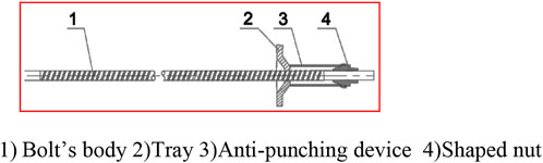
FIGURE 1. Structure of the constant-resistance, energy-absorbing, and anti-scouring bolt.
The deflection angle is defined as the angle between the axial direction of the bolt and the normal direction of the bearing surface; ideally, the anchor should be driven vertically into the surrounding rock or coal wall, at which point the deflection angle is 0°. However, in actual engineering, the bolt produces an angle between the anchor rod and the surface of the surrounding rock of the roadway due to construction errors (errors in drilling bolt holes), design requirements for roadway support, unevenness around the surrounding rock (e.g., flake bubbles in the coal rock body), etc. The angle between the axial direction of the bolt and the normal direction of the bearing surface of the surrounding rock is the deflection angle θ, as shown in the schematic diagram in Figure 2.
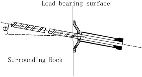
FIGURE 2. Diagram of the deflection angle θ of a constant-resistance, energy-absorbing, and anti-scouring bolt.
In practice, bolts are constructed in the following sequence: hole drilling, anchor bolt insertion, insertion of the tray and anti-punching device and, finally, tightening of the nut to apply preload. As the centre hole diameter of the pallet is slightly larger than the diameter of the rod, the rod can be deflected at a certain angle, defining the maximum angle at which the centre hole allows the bolt to be deflected, i.e., the maximum deflection angle. When the deflection angle is less than the maximum, the pallet can be tightened against the load bearing surface, but the impact protector is not sufficiently tightened against the pallet (see Figure 2). When the deflection angle is greater than the maximum, the pallet does not fit tightly against the load bearing surface; therefore, under the action of preload, the pallet bends or shears the rod, which is not conducive to maintenance of the bolt’s tensile performance.
To determine conditions that allow full use of the tensile properties of the rod, a theoretical analysis of the maximum deflection angle was carried out. The positioning of the bolt and the pallets was simplified, as shown in Figure 3, and the geometric relationship was obtained from:
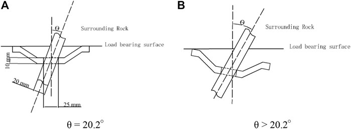
FIGURE 3. Position relation of the pallet and the bolt. (A) θ = 20.2° and (B) θ > 20.2°.
Solution: θ1 = 20.2° and θ2 = -63.8° (rounded off).
From the results, it can be seen that the maximum deflection angle that can be generated between the bolt and the pallet is 20.2° (Figure 3A).When the deflection angle is less than 20.2°, the pallet only acts in the axial direction of the rod; when the deflection angle is greater than 20.2°, the pallet cannot be tightened against the load-bearing surface (Figure 3B), and under the action of the preload or external load, the wall of the central hole of the pallet will exert a lateral force on the bolt, which results in bending or shear deformation of the rod.
Principles of application of constant-resistance, energy-absorbing, and anti-scouring bolts in the presence of a deflection angle
Bolts have a much larger dimension in the lengthwise direction than the other two directions, providing mainly tensile and shear resistance, with very little bending and compression resistance (Wu 2009). Based on the theory of yielding scour protection support and the principles of ideal energy-absorbing device design (Pan et al., 2014a; Pan et al., 2014b; Tang et al., 2022), it is proposed that constant-resistance, energy-absorbing, and anti-scouring bolts in the presence of deflection angles should have the following basic characteristics: 1) Reasonable deformation load threshold. The load carrying capacity of the anti-puncher in the force-displacement curve of the anchor rod is the deformation load threshold of the anchor rod, which is set at 90–110% of the yielding force of the rod to ensure that the anti-punching device is playing a role near the yielding stage of the rod. 2) High stroke efficiency. The performance of the bolt giving way depends largely on the adequacy of the deformation of the anti-punching device, which can be considered adequate when the stroke efficiency is 85–99%. 3) Constant reaction force. The reaction force of the anti-punching device should be kept as constant as possible during the deformation of the surrounding rock, which ensures that it protects the bolt. 4) A stable and repeatable deformation damage pattern to ensure the reliability of the anti-punching device in complex situations. 5) High load-bearing capacity. Anchor rods with a deflection angle should have a breaking force that is not less than 85% of the breaking force under axial tension to be considered as having a high support resistance to the surrounding rock. 6) Good energy absorption performance. The energy absorption of the bolt should be higher than 75% of its energy absorption in axial tension to allow good energy absorption performance. 7) Good deflection capacity. The yield distance of the bolt should be higher than 80% of its yield distance in the tensile test, which indicates good deflection capacity.
Influence of deflection angle on mechanical properties of an anchor bolt under static load
Using ABAQUS software, the finite element models of the rod, pallet, energy absorber, and profile nut were built according to the dimensions described above, and explicit dynamic analysis was performed. The material parameters for the bolt’s body, pallets, anti-punching device, and shaped nuts were set in the properties module. The settings included density of 7850 kg/m3, modulus of elasticity of 210 GPa, and Poisson’s ratio of 0.3. The plasticity parameters were taken from laboratory tensile tests of the bolt and converted to yield strength of 400 MPa and tensile strength of 588 MPa. The rods were set for flexible damage in ductile metal damage. The anti-punching device used self-contact, other surface contact methods were set to surface-to-surface contact, the contact method was the penalty contact method, and the coefficient of friction was taken as 0.3. The boundary conditions of the model were set: the left end of the bar was completely fixed and only axial displacement was allowed at 10 mm from the pallet. The model was assembled in the relative positions shown in Figure 1. A rigid plate with a diameter greater than that of the bolt’s body was displaced 450 mm to the right from the left side of the pallet, treating the plate as a load bearing surface with an angle of the bolt. Mesh settings: C3D8R cells were used for each part, the mesh shape was hexahedral, the mesh size of the pallet and bolt were set to 5, the size of the anti-punching device was set to 2, the bolt’s cell type was set to hourglass control for stiffness, and the cell delete was set.
To determine the influence of the deflection angle on the mechanical properties of the constant-resistance, energy-absorbing, and anti-scouring bolts under static load, simulations of the tensile process of the bolts were carried out at deflection angles of 0, 3, 5, 7, 10, 13, 15, 17, 20, 23, 25, 27, 30, 33, and 35°. The mechanical properties of the bolts at different angles are shown in Table 1.
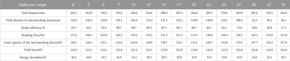
TABLE 1. Comparison of mechanical properties of bolts with different deflection angles.
Effect of deflection angle on deformation performance
The deformation process of the bolt at partial deflection angles is shown in Figure 4. The displacement of the bolt/stroke efficiency of the anti-punching device—deflection angle curve is shown in Figure 5. Figures 4, 5 and Table 1 indicate that:
1) With a deflection angle of 0° (Figure 4A), the bolt as a whole underwent only axial tension and no bending deformation. In the deflection angle range of 3–35° (Figures 4B–D), the pallet-nut section of the bolt was deformed in “stretching + bending”. At a deflection angle of 27°, the pallet did not fit sufficiently with the anti-punching device due to the angle, and the stress was concentrated on the side of the anti-punching device, which was the first to reach its strength limit and show damage. These data demonstrate that the deflection angle changes the deformation of the bolt from axial tension to a combination of “stretching + bending”.
2) The let-off distance of the bolt is the sum of the displacement of the bolt’s body and the deformation distance of the anti-puncher. With a deflection angle in the range of 0–20°, the nut was first in contact with the side of the anti-puncher, the compressive stress increased, and the bolt was curved by the eccentric load. The angle of deflection increased and the degree of pole bending increased. The locations of the stress concentration in the anti-puncher and the bending of the pole took the lead in plastic deformation and damage, with a reduction in both pole displacement and anti-puncher deformation distance. The anchor deflection distance decreased from 365.3 mm to 266.8 mm, with an average decrease of 4.93 mm/°. In the range of 20–27°, the pallet contacted the anti-puncher first on one side, and stresses were concentrated and the pallet acted laterally on the bolt’s body. The direction of action of the anti-puncher on the nut was opposite to the direction of force on the rod and the deformation of the bolt was reduced. There was a small variation in the deflection distance in the range of 270.6 mm–262.9 mm. In the range of 27–35°, the stress concentration of the pallet on the anti-puncher increased and the local plastic deformation of the anti-puncher was too large. The bending of the rod was large and the expansion of the anti-puncher was hindered. The yield distance dropped from 262.9 mm to 164.8 mm, with an average drop of 12.26 mm/°. These data indicate that the yield distance decreases overall with increasing deflection angle. The yielding distance decreased to a lesser extent before 20°; it remained almost constant from 20 to 27° and decreased to a greater extent after 27°.
3) Stroke efficiency is the ratio of the deformation distance to its own length. During the “stretching and bending” deformation of the bolt, the side of the anti-puncher was first in contact with the nut, resulting in stress concentration and plastic deformation. The increase in angle increased the degree of deformation and decreased the distance of deformation. For deflection angles in the range of 0–23°, the yield distance of the anti-punching device reduced from 142.0 mm to 130.0 mm and the stroke efficiency reduced from 94.7% to 86.7%. In the range of 23–35°, the deformation distance was reduced from 130.0 mm to 26.1 mm and the stroke efficiency dropped rapidly from 86.7% to 17.3%. These data indicate that the larger the deflection angle, the smaller the deflection distance and the lower the stroke efficiency. Before 23°, the deformation distance and stroke efficiency of the anti-puncher device were less influenced by the deflection angle; after 23°, they were greatly influenced by the deflection angle.
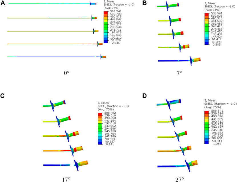
FIGURE 4. Deformation of bolt and anti-punching device at partial deflection angles.
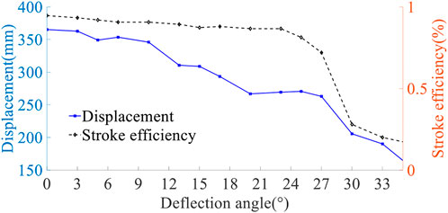
FIGURE 5. Displacement of the bolt/stroke efficiency of the anti-punching device—deflection angle curve.
Influence of deflection angle on load bearing performance
The anchor rod force-displacement curves for different deflection angles are shown in Figure 6. The breaking force of bolt/load bearing force of the anti-punching device deflection angle curve is shown in Figure 7. The load bearing force of the anti-punching device was defined as the value of the anti-punching reaction force during the expansion stage. Figure 6, Figure 7, and Table 1 indicate that:
1) When the deflection angle was in the range of 0–20°, there was still a gap between the centre hole of the pallet and the rod body. The pallet had no force on the pole, but there was a certain angle between the anti-puncher and the pallet, which made them unevenly stressed. The pole was bent and deformed. The bolt breaking force decreased gradually in the range of 171.1–134.3 kN. In the range of 20–33°, the pole was affected by the composite lateral action of the pallet and the nut, and resulted in less deformation of the pole and a small increase in load capacity. The breaking force rose gradually in the range of 134.3–147.0 kN. The bending of the bolt was greater at 35° and the load capacity was greatly reduced. The breaking force was 131.8 kN. These data indicate that the breaking force of the anchor is not linearly related to the angle of deflection, but rather tends to fall, then rise slightly and then continue to fall.
2) After the bending and deformation of the rod, the anti-puncher was squeezed by the pallet, in addition to the frictional and pressure effects with the nut. Plastic damage occurred at the contact position. As the angle increased, the deformation of the anti-puncher increased. The force state changed from friction to friction and plastic deformation, and the anti-puncher reaction force increased significantly. The load carrying capacity of the anti-puncher increased from 120.0 kN to 137.7 kN over the range of 0–30° of deflection. The rate of increase was 0.57 kN/° over the range of 0–20° and 0.63 kN/° over the range of 20–30°. These data indicate that the load-bearing capacity of the anti-punching device increases with increase of deflection angle.
3) The force-displacement curve of a constant-resistance, energy-absorbing, and anti-scouring bolt consists of five parts: “linear elastic stage”, “expansion stage”, “yielding stage”, “strengthening stage”, and “breaking stage” (Tang et al., 2022). The change in position of the expansion stage reflects the strength between load-bearing properties of the anti-punching device and bolt. The anchor pull-off force decreased as the angle increased, while the load-bearing capacity of the anti-puncher increased as the angle increased. In the deflection angle range of 0–5°, the expansion stage occurred after the linear elastic stage and before the yielding stage. At a deflection angle of 7°, the expansion phase occurred partly after the inline elastic stage, partly after the yielding stage, and before the strengthening stage. In the range of 10–17°, the expansion phase occurred after the yielding phase and before the strengthening stage; in the range of 20–35°, the expansion stage occurred simultaneously with the strengthening stage. The curve of the expansion stage is smoother at all deflection angles, indicating that the bolt had a constant reaction force. The position of the spreading stage in the curve varied for different deflection angles.
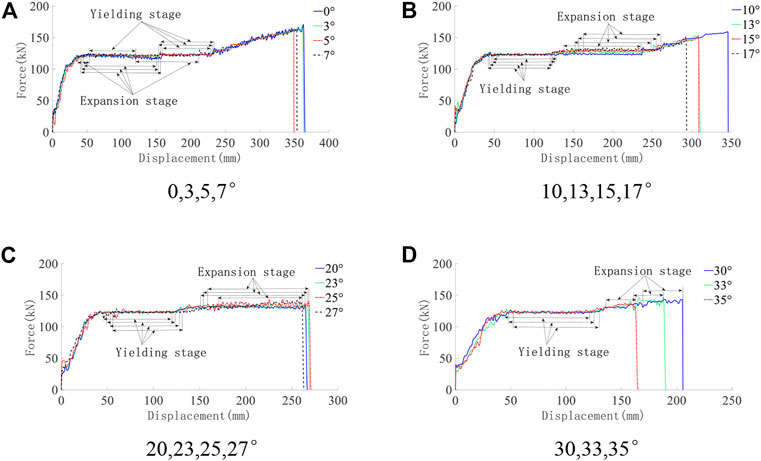
FIGURE 6. Force-displacement curves for bolt with different deflection angles. (A) 0, 3, 5, and 7°, (B) 10, 13, 15, and 17°, (C) 20, 23, 25, and 27°, and (D) 30, 33, and 35°.
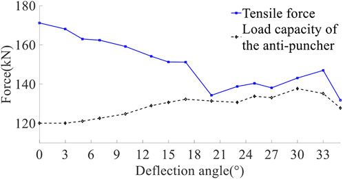
FIGURE 7. Breaking force of bolt/load bearing force of anti-punching device—deflection angle curve.
Effect of deflection angle on energy absorption performance
The absorption energy-displacement curves for different deflection angles are shown in Figure 8 and the absorption energy-deflection angle curves are shown in Figure 9. Figure 8, Figure 9, and Table 1 indicate that:
1) The area enclosed by the force-displacement curve reflects the amount of energy absorbed by the anchor. The bearing capacity and yield distance of the bolt decreased as the deflection angle increased, so the amount of energy absorbed should also decrease as the deflection angle increases. In the deflection angle range of 0–20°, the energy absorbed by the anchor dropped from 46.2 kJ to 32.0 kJ. In the range of 20–27°, the energy absorption fluctuated slightly within 31.9–33.0 kJ; in the range of 27–35°, it decreased from 31.9 kJ to 18.7 kJ. These data demonstrate that energy absorption decreases non-linearly with increase of the deflection angle.
2) In the range of 0–20°, the reduction rate of the energy absorption of the bolt was 0.71 kJ/°; in the range of 27–35°, the absorbed energy decreased from 31.9 kJ to 18.7 kJ, with an average reduction rate of 1.65 kJ/° (> 0.71 kJ/°). These data indicate that the bolt had good energy absorption performance before 20°, but performance was severely reduced in the range of 27–35°.
3) The ratio of energy absorption to displacement (energy absorption per unit of displacement) is the slope of the energy absorption-displacement curve, and the energy absorption per displacement of the bolt at each deflection angle is 7.88 kJ/mm, 7.88 kJ/mm, 7.88 kJ/mm, 7.89 kJ/mm, 7.97 kJ/mm, 7.99 kJ/mm, 7.99 kJ/mm, 7.99 kJ/mm, 8.19 kJ/mm, 8.19 kJ/mm, 8.18 kJ/mm, 8.19 kJ/mm, 8.39 kJ/mm, 8.39 kJ/mm, 8.39 kJ/mm, and 8.39 kJ/mm, respectively. These data demonstrate that the amount of energy absorbed by the anchor rod increases linearly with displacement for different deflection angles. The effect of deflection angle on the energy absorption per displacement of bolt was minor.
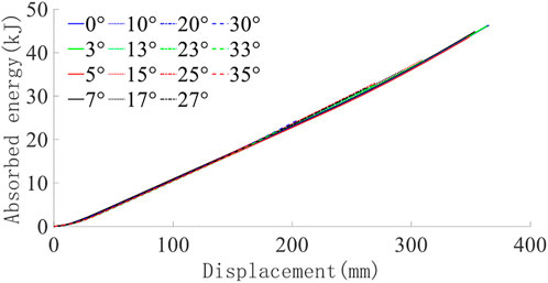
FIGURE 8. Energy absorption-displacement curves for bolts at different angles.
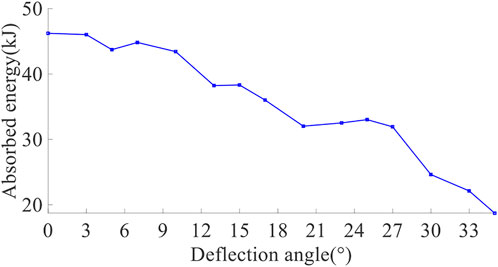
FIGURE 9. Energy absorption—deflection angle curve.
Determination of the scope of application of constant-resistance, energy-absorbing, and anti-scouring bolts
Through the above analysis and based on the design principles, the indicators corresponding to different deflection angles have been collated and analysed, and the percentage of each indicator is shown in Table 2.
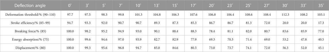
TABLE 2. Percentage of each indicator for bolts with different deflection angles.
We studied the reasonable range of deflection angles based on the applicable principles presented earlier in this article. The deformation process of the bolt includes the “elastic stage”, “yielding stage”, “expansion deformation stage”, “strengthening stage”, and “breaking stage”, indicating that the bolts have a repeatable deformation mode. The deformation stage of the anti-punching device is the expansion stage. The force-displacement curve of the bolt at each angle has a constant reaction force with a small floating range of reaction force in the expansion stage. All angles in the deformation threshold indicator, except 30°, are in accordance with the design principles. The stroke efficiency indicators are in accordance with the design principles for all angles except 25, 27, 30, 33, and 35°. At 0–17° and 33°, the breaking force percentage indicators are in accordance with the design principles. At 0–17° the energy absorption ratio indicator is in accordance with the design principles. As the bolt should all satisfy the above design principles when there is a deflection angle, our analysis demonstrates that the deflection angle of the anchor bolts in the range of 0–17° is still considered applicable.
Analysis of mechanical properties of bolts under impact loading
In this study, we investigated the mechanical properties of constant-resistance, energy-absorbing, and anti-scouring bolts under impact loading in the presence of deflection angle. Combined with the results of static analysis, we chose to use ABAQUS finite element software to simulate the impact loading of the bolt with a deflection angle of 17°. Due to the large amount of impact energy released by the impact ground pressure working at the pallets of the bolts, a rigid body with mass and velocity was used to simulate the impact energy of the surrounding rock and to study the mechanical properties of the bolts under the action of different impact energies and impact velocities. The parameters were set in the same way as for static loads, with an angle of 17° between the rigid plate and the pallet.
Effect of impact energy on mechanical properties of bolts
The impact velocity was 6 m/s and the impact energy was 50, 500, and 5000 kJ. Separate impact loading simulations were carried out on constant-resistance, energy-absorbing, and anti-scouring bolts with a deflection angle of 17°. The deformation of the bolts is shown in Figure 10, the force-time curve of the bolts is shown in Figure 11, the energy absorption-displacement is shown in Figure 12, and the mechanical properties are shown in Table 3. From Figures 10–12 and Table 3, it can be seen that:
1) At different impact energies, the deformation process of the bolt underwent the “elastic stage”, the “yielding stage”, the “reinforcement stage + anti-punching device expansion deformation stage”, the “breaking stage”, and the “breakage stage”. These data indicate that the bolt has a repeatable deformation pattern.
2) As the impact energy increased, the load-bearing capacity of the anti-punching device remained between 139.6 and 140.3 kN, which indicates that the anti-punching device has a relatively constant reaction force.
3) Under the impact energy of 50, 500, and 5000 kJ, the deflection distances of the bolt (equal to the bolt’s body displacement plus the deformation distance of the anti-punching device) were 293.5, 306.8, and 305.8, mm respectively, and the deformation distances of the anti-punching device were 127.4, 141.1, and 140.3 mm, respectively. Stroke efficiency was 84.9, 94.1, and 93.5% respectively. The displacement of the bolt’s body was 166.1, 165.7, and 165.5 mm, respectively. These data indicate that the impact energy has a minor effect on the deformation distance and stroke efficiency of the bolt and on yield distance of the anti-puncher.
4) At 50, 500, and 5000 kJ impact energy, the yield force of the bolt was 125.8, 126.7, and 126.4 kN, respectively, and the breaking force was 139.7, 146.5, and 146.2 kN, respectively. The impact energy had a small effect on the yield force, breaking force, and load bearing capacity of the anchor.
5) Under the action of 50, 500, and 5000 kJ impact energy, the energy absorption of anchor rods was 36.9, 38.9, and 38.6 kJ respectively, indicating that the impact energy has a small effect on the energy absorption index of anchor rods.
6) The impact resistance times were 67.6, 55.4, and 54.1 ms at 50, 500, and 5000 kJ impact energy, respectively, indicating that the impact resistance time decreases with increasing impact energy.
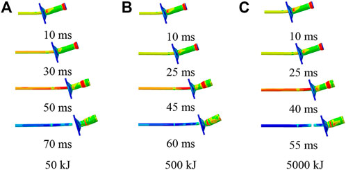
FIGURE 10. Deformation of bolt with time at different impact energies.
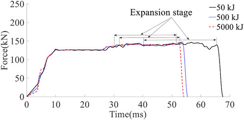
FIGURE 11. Anchor force-time curve.
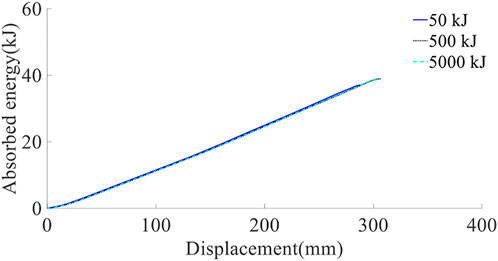
FIGURE 12. Anchor energy absorption-displacement curve.
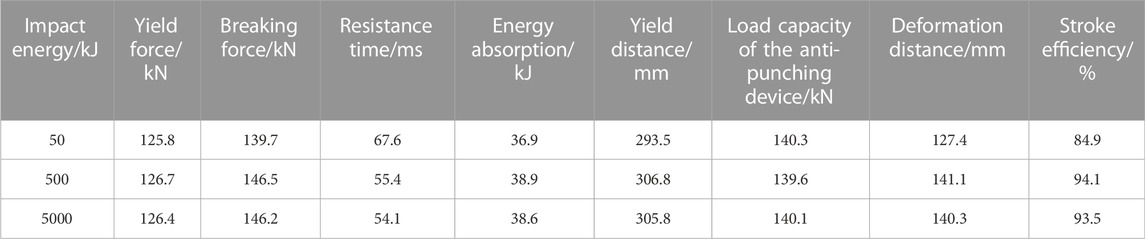
TABLE 3. Mechanical properties of anchor bolts at different impact energies.
Effect of impact velocity on mechanical properties of bolts
The impact energy was chosen as 50 kJ and the impact velocities were 2, 4, 6, and 8 m/s, respectively. The impact loading simulations were carried out for a constant-resistance, energy-absorbing, and anti-scouring bolt with a deflection angle of 17°. The bolt’s deformation is shown in Figure 13, the force-time curve of the bolt is shown in Figure 14, the energy absorption-displacement is shown in Figure 15, and the mechanical properties of the anchor rod are shown in Table 4. From Figures 13–18 and Table 4, it can be seen that:
1) At impact speeds of 2, 4, 6, and 8 m/s, the deformation process of the bolt experienced the “elastic stage”, the “yielding stage”, and the “reinforcement + expansion deformation stage”, indicating that the bolt has a repeatable deformation mode at different impact speeds.
2) As the impact velocity increased, the load-bearing force of the anti-punching device remained between 140.3 and 151.5 kN, indicating that the anti-punching device has a relatively constant reaction force.
3) At impact velocities of 2, 4, 6, and 8 m/s, the bolt yield distances were 213.2, 233.1, 293.5, and 321.4 mm, respectively. The deformation distances of the anti-punching device were 41.7, 63.2, 127.4, and 144.1 mm, and the stroke efficiencies were 27.8, 42.1, 84.9, and 96.1%, respectively. The displacements of bolt’s body were 171.5, 170.0, 166.1, and 177.3 mm, respectively. These data indicate that the impact velocity has a small effect on the displacement of the bolt. The yielding distance of the bolts, and the deformation distance and stroke efficiency of the anti-punching device increased with the increase of the impact velocity.
4) At impact speeds of 2, 4, 6, and 8 m/s, the yield forces of the bolt were 124.1, 124.7, 125.8, and 126.1 kN respectively; the tensile forces were 152.7, 149.6, 139.7, and 155.7 kN, respectively, and the load bearing force of the anti-punching device was 151.5, 142.6, 140.3, and 141.5 kN, respectively. These data indicate that impact velocity has a minor effect on the yield force and breaking force of the bolt. The load breaking force of the anti-punching device remained essentially the same with the increase of impact velocity.
5) The energy absorption of the bolt was 26.5, 28.9, 37.0, and 42.3 kJ, respectively, for impact velocities of 2, 4, 6, and 8 m/s, indicating that energy absorption increases approximately linearly with impact velocity.
6) The impact velocities of the bolts were 125.1, 75.0, 67.6, and 60.8 ms for impact velocities of 2, 4, 6, and 8 m/s, respectively, indicating that impact resistance time decreases with increasing impact velocity.
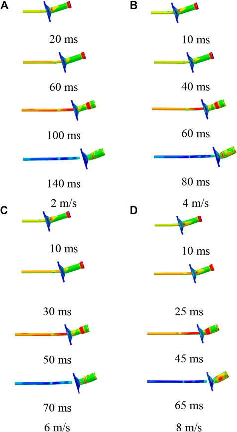
FIGURE 13. Deformation of bolt with time at different impact velocities.
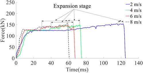
FIGURE 14. Anchor force-time curve.
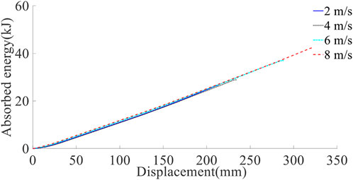
FIGURE 15. Anchor energy absorption-displacement curve.
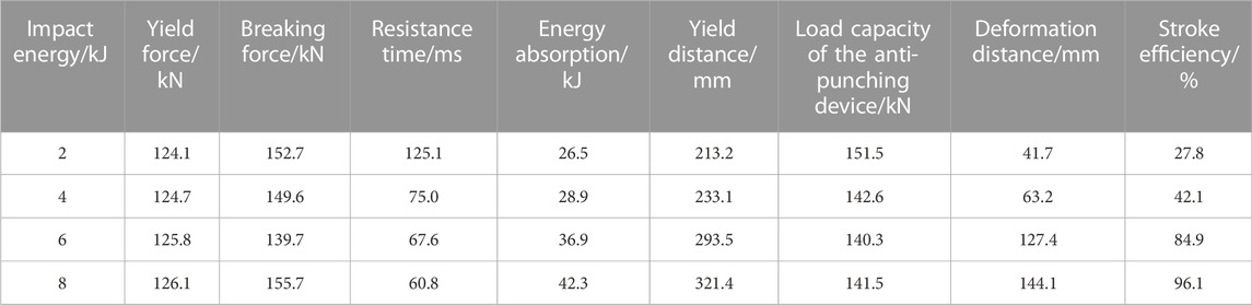
TABLE 4. Mechanical properties of anchor bolts at different impact velocities.

FIGURE 16. Anchor give way distance at different impact velocities.
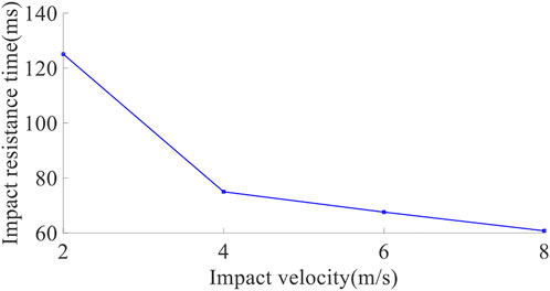
FIGURE 17. Anchor impact resistance time for different impact velocities.
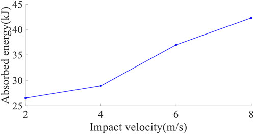
FIGURE 18. Absorption energy of anchor bolt at different impact velocities.
Conclusion
Constant-resistance, energy-absorbing, and anti-scouring bolts were simulated by static loading at different deflection angles and by impact loading of the anchors at a deflection angle of 17°. The main conclusions of this study are:
1) Design principles for constant-resistance, energy-absorbing, and anti-scouring bolts at deflection angles are proposed.
2) At the angle of deflection, the deformation process of the bolt changes from an axially stretching form to a “stretching and bending” form. The bolt has a repeatable deformation mode and a relatively constant reaction force.
3) As the deflection angle increases, the load bearing force of the anti-punching device increases, the breaking force of the bolt increases after decreasing and then decreases again, the energy absorption decreases non-linearly, the yield distance of the bolt decreases (the displacement of the bolt remains basically the same and the deformation distance of the anti-punching device decreases), and the stroke efficiency decreases. According to the principles of constant-resistance, energy-absorption, and anti-scouring bolt design, it was determined that the bolt is still applicable within a deflection angle of 0–17°.
4) Impact energy has a minor effect on the indices of yield force, breaking force, and energy absorption of the bolt. The impact resistance time decreases non-linearly with increase in impact energy.
5) Impact velocity has a minor effect on the yield force and breaking force of the bolt. The impact resistance time and the load bearing force of the anti-puncher device both decrease with increasing impact velocity. The yield distance of the bolt, and the deformation distance and stroke efficiency of the anti-punching device all increase with increasing impact velocity. Absorption energy increases linearly with increasing impact velocity.
Data availability statement
The original contributions presented in the study are included in the article/Supplementary material; further inquiries can be directed to the corresponding author.
Author contributions
Conceptualization, ZT; methodology, ZT; software, ZT and HW; validation, JL; investigation, HW; resources, ZT; data curation, HW; writing—original draft preparation, HW; writing-review and editing, ZT; visualization, HW; supervision, DC; project administration, ZT; funding acquisition, ZT.
Funding
This study was funded by the National Natural Science Foundation of China (51804152, 52174116), Liaoning Revitalization Talents Program (XLYC1907168), and Natural Science Foundation of Liaoning Province (2019-MS-163, 2021-MS-337).
Conflict of interest
The authors declare that the research was conducted in the absence of any commercial or financial relationships that could be construed as a potential conflict of interest.
Publisher’s note
All claims expressed in this article are solely those of the authors and do not necessarily represent those of their affiliated organizations, or those of the publisher, the editors, and the reviewers. Any product that may be evaluated in this article, or claim that may be made by its manufacturer, is not guaranteed or endorsed by the publisher.
References
Dong, J. J., Zheng, G. Y., and Yang, D. (2022). FBG bolts used for bolt support for safety monitoring of mining roadways. J. Min. Saf. Eng. 39 (02), 328–334. doi:10.13545/j.cnki.jmse.2021.0224
Dou, L. M., Tian, X. Y., Cao, A. Y., Gong, S. Y., He, H., He, J., et al. (2022). Present situation and problems of coal mine rock burst prevention and control in China. J. China Coal Soc. 47 (01), 152–171. doi:10.13225/j.cnki.jccs.yg21.1873
Gong, W. L., Sun, Y. X., Gao, X., He, M. C., and Qi, P. (2018). Dynamic characteristics of constant-resistance-large-deformation bolts based on weight-dropping tests. Chin. J. Rock Mech. Eng. 37 (11), 2498–2509. doi:10.13722/j.cnki.jrme.2018.0674
Guo, J. G., Li, Y. H., He, F. L., Chen, J. H., Zhao, G. M., and Zhang, J. W. (2021). Pullout simulation on fully grouted rock bolts based on residual shear strength. Rock Soil Mech. 42 (11), 2953–2960. doi:10.16285/j.rsm.2021.0544
Hao, C. S., Shang, D., Sun, M., Zhang, P., and Chen, Z. (2017). Supporting parameters impact on pretensioned distribution of roadway. Coal Technol. 36 (03), 17–21. doi:10.13301/j.cnki.ct.2017.03.007
He, M. C., Li, C., Gong, W. L., Wang, J., and Tao, Z. G. (2016). Support principles of NPR bolts/cables and control techniques of large deformation. Chin. J. Rock Mech. Eng. 35 (08), 1513–1529. doi:10.13722/j.cnki.jrme.2015.1246
Jiang, Y. D., Pan, Y. S., Jiang, F. X., Dou, L. M., and Ju, Y. (2014). State of the art review on mechanism and prevention of coal bumps in China. J. China Coal Soc. 39 (02), 205–213. doi:10.13225/j.cnki.jccs.2013.0024
Kang, H. P., Wang, J. H., and Lin, J. (2007). High pretensioned stress and intensive bolting system and its application in deep roadways. J. China Coal Soc. (12), 1233–1238. doi:10.13225/j.cnki.jccs.2007.12.003
Liu, H. Y., Zuo, J. P., Liu, D. J., Li, C. Y., Xu, F., and Lei, B. (2021). Optimization of roadway bolt support based on orthogonal matrix analysis. J. Min. Saf. Eng. 38 (01), 84–93. doi:10.13545/j.cnki.jmse.2019.0420
Pan, Y. S. (2018). Instability theory of coal mine impact ground pressure disturbance response and application. J. Coal 43 (08), 2091–2098. doi:10.13225/j.cnki.jccs.2018.0604
Pan, Y. S., Ma, X., Xiao, Y. H., and Li, Z. H. (2014b). Numerical analysis and experimental study of a coal mine anti-impact and energy-absorption supporting component. J. Exp. Mech. 29 (02), 231–238. doi:10.7520/1001-4888-13-089
Pan, Y. S., Xiao, Y. H., Li, Z. H., and Wang, K. X. (2014a). Study of tunnel support theory of rockburst in coal mine and its application. J. China Coal Soc. 39 (02), 222–228. doi:10.13225/j.cnki.jccs.2013.2015
Tang, Z., Wu, H., Liu, Y., Pan, Y., Lv, J., and Chang, D. (2022). Numerical analysis of mechanical characteristics of constant-resistance, energy-absorbing and anti-scour bolts. Materials 15 (10), 3464–3510. doi:10.3390/ma15103464
Tang, Z., Wu, H., Lv, J., Xin, Z., and Zuo, W. (2021). Study on mechanical characteristics of energy-absorbing and anti-scour bolts. Complexity 2021, 1–9. doi:10.1155/2021/8876517
Wang, A. W., Fan, D. W., Pan, Y. S., Zhao, B. Y., and Dai, L. P. (2022). Expansion-friction energy-absorption anti-impact cable and its mechanical characteristics. J. China Coal Soc. 47 (02), 695–710. doi:10.13225/j.cnki.jccs.xr21.1728
Wang, A. W., Pan, Y. S., Zhao, B. Y., and Sheng, J. Q. (2017). Static and dynamic mechanical properties of energy absorption bolts (cable) and field tests. Chin. J. Geotechnical Eng. 39 (07), 1292–1301. doi:10.11779/CJGE201707016
Wang, Q., He, M. C., Xu, S., Xin, Z. X., Jiang, B., and Wei, H. Y. (2022). Mechanical properties and engineering application of constant resistance energy absorbing bolt. J. China Coal Soc. 47 (04), 1490–1500. doi:10.13225/j.cnki.jccs.2021.0383
Wu, Y. Z., Kang, H. P., Ding, J., Wu, J. X., and Wang, Q. (2015). Development and application of ultrahigh-heat processed rock bolts. J. China Coal Soc. 40 (02), 308–313. doi:10.13225/j.cnki.jccs.2014.0283
Wu, Y. Z. (2009). Study on stress and supporting effects of bolt body“. China Coal Research Institute.
Zhang, B., Zhang, Z. Q., Wang, B., and Zhou, L. (2016). Experimental study of application of yielding bolt to large deformation tunnel. Rock Soil Mech. 37 (07), 2047–2055. doi:10.16285/j.rsm.2016.07.028
Zhang, H. J., Li, H. Y., Zhang, T. P., Wang, Q., Wang, W., Wang, X., et al. (2019). Research and engineering application of high pre-stressed resistance enhancement large deformation bolt in deep soft rock roadway. J. China Coal Soc. 44 (02), 409–418. doi:10.13225/j.cnki.jccs.2018.0495
Zheng, G., Lei, Y. W., Cheng, X. S., Li, X. Y., and Wang, R. Z. (2020). Influences and mechanisms of anchor failure on anchored pile retaining system of deep excavations. Chin. J. Geotechnical Eng. 42 (03), 421–429. doi:10.16285/j.rsm.2021.1715
Keywords: deflection angle, energy-absorbing anti-scour anchor, numerical analysis, impact energy, impact velocity
Citation: Tang Z, Wu H, Lv J and Chang D (2023) Effects of deflection angle on the mechanical properties of constant-resistance, energy-absorbing, and anti-scouring bolts. Front. Earth Sci. 10:1046135. doi: 10.3389/feart.2022.1046135
Received: 16 September 2022; Accepted: 28 November 2022;
Published: 19 January 2023.
Edited by:
Shibing Huang, Wuhan University of Science and Technology, ChinaReviewed by:
Youjun Ning, Southwest Petroleum University, ChinaIzzet Sakalli, Eastern Mediterranean University, Turkey
Copyright © 2023 Tang, Wu, Lv and Chang. This is an open-access article distributed under the terms of the Creative Commons Attribution License (CC BY). The use, distribution or reproduction in other forums is permitted, provided the original author(s) and the copyright owner(s) are credited and that the original publication in this journal is cited, in accordance with accepted academic practice. No use, distribution or reproduction is permitted which does not comply with these terms.
*Correspondence: Zhi Tang, dGFuZ3poaTAxMjdAMTYzLmNvbQ==