 Pinpin Li
 Xun Huang
 Feng Lu
 Wenge Qiu1
 Linlong Li
 Yi Wang
 Zhenyu Chen
94% of researchers rate our articles as excellent or good
Learn more about the work of our research integrity team to safeguard the quality of each article we publish.
Find out more
ORIGINAL RESEARCH article
Front. Earth Sci., 25 January 2023
Sec. Environmental Informatics and Remote Sensing
Volume 10 - 2022 | https://doi.org/10.3389/feart.2022.1040461
This article is part of the Research TopicAdvances and Applications of Artificial Intelligence and Numerical Simulation in Risk Emergency Management and TreatmentView all 22 articles
In this paper, the performance of a high-pressure grouting material and consolidation body, the key parameters of tunnel surrounding rock reinforcement, and the field reinforcement effect are compared and studied. The results show that 1) the compressive strength, elastic modulus, and seepage resistance of the consolidation body are related to the water–cement ratio. The permeability of the consolidation body increases with increasing water–cement ratio under the constant head; under the condition of a certain water–cement ratio, the strength increases with an increase in cement content. To meet the construction requirements and the slurry stability, a small water–cement ratio is appropriate. 2) Slurry pressure, rotary spray speed, and lifting speed on the single pile static load bearing capacity have a significant impact. Under the same static load conditions, the greater the slurry pressure, the lower the cumulative settlement value of the single pile, the cumulative settlement value increases less, and the amount of change in rebound is the same; with the increase in the rotational speed of the rotary spray, the lower the cumulative settlement value of the single pile, and the rate of change of the cumulative settlement value of the single pile decreases; and with the increase in the lifting speed, the cumulative settlement value of the single pile increases and the rate of change of the cumulative settlement value decreases. 3) The pile body cement soil is more uniform, has high strength, and is brittle, and the stratum where the slurry part is located is a loose powder clay layer and sandy layer. 4) After high-pressure jet grouting pile reinforcement, the top surrounding rock is more stable after the excavation of an ultra-shallow buried tunnel, the fissures between the surrounding rocks are filled with cement soil consolidation, and the integrity is improved. Certain piles also play a certain role in stopping water; high-pressure jet grouting pile reinforcement to improve the integrity of the surrounding rock played a role in consolidating the weak soil layer above the tunnel vault, creating conditions for the safe excavation of the shallow buried section of the tunnel.
With the rapid development of high-speed railroad network construction, highway tunnels often encounter the problem of excavating ultra-shallow buried tunnels in strongly weathered strata. Due to the very shallow burial depth, the stratum in which the tunnel is located is severely weathered, rock fissures are developed, and the surrounding rock is poorly self-stabilized and prone to surface cracking and collapse after tunnel excavation (Davis et al., 1981; Zhou et al., 2013; Cui et al., 2022), which poses a great threat to the service life and operation safety of the tunnel (Li et al., 2022; Lu et al., 2022). The common accident types and frequency statistics of tunnels are shown in Figure 1. Due to the high frequency of collapse accidents in tunnel construction and the highest number of single fatalities among all accident types (Wang et al., 2009; Zhang et al., 2014; Li et al., 2022), often accompanied by damage to the structure, engineering delays, and serious environmental impacts in the surrounding area, collapse accident prevention is at the top of disaster prevention and control. Many factors cause collapse, including geological factors, survey factors, design factors, and construction factors, and the latter three are controlled by geological factors, so dealing with geological factors is the focus of collapse prevention and control (Hu and Qin, 2013). Due to the complex geological conditions and the lack of mature experience and corresponding standard specifications, effective reinforcement of the stratum, prevention of collapse of the surrounding rock, and ensuring construction safety are the key factors for ultra-shallow buried tunnel construction in strongly weathered strata (Chen et al., 2013).
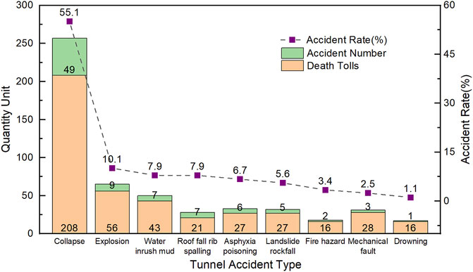
FIGURE 1. Statistics of tunnel accident type and occurrence frequency.
To improve the surrounding rock in strongly weathered strata and reduce the risk of a tunnel collapse, it is often necessary to pre-reinforce the tunnel-surrounding rock before the excavation of ultra-shallow buried tunnels. High-pressure jet grouting piles are created by using high-pressure cement mortar after drilling holes in the ground and using high-pressure slurry to quickly cut and mix the soil to create the cement and soil mix. High-pressure jet grouting piles have become a reinforcement technique used to improve the ground and solve most of the weak ground problems (Brandsttter et al., 2001). Jet grouting systems are divided into three types according to the delivery mechanism (see Figure 2): single-fluid, two-fluid, and three-fluid (Nikbakhtan and Osanloo, 2009). In a single-fluid system, the injected fluid is cement soil; in a two-fluid system, cement soil and compressed air are injected. The combined action of high-pressure grout and air results in a greater percentage of soil being removed and replaced by the grout; in the three-fluid system, slurry, air, and water are injected. This triple combination removes a much higher percentage of soil and the system can be used to replace soil almost completely with cement soil. In general, the most important parameters affecting the design of jet grouting are the soil type, the inflow of the slurry mixture, the injection energy, the slurry flow rate, the rotational speed, and the lifting speed (Nikbakhtan and Rahmani, 2010). The rotary jet pile system can be applied to different application scenarios with different types of soils by adjusting the technical parameters, such as increasing the bearing capacity, increasing the permeability of gravelly soils, reducing the settlement of soft clay soils, and resisting the liquefaction of sandy soils (Hasan and Canakci, 2022).
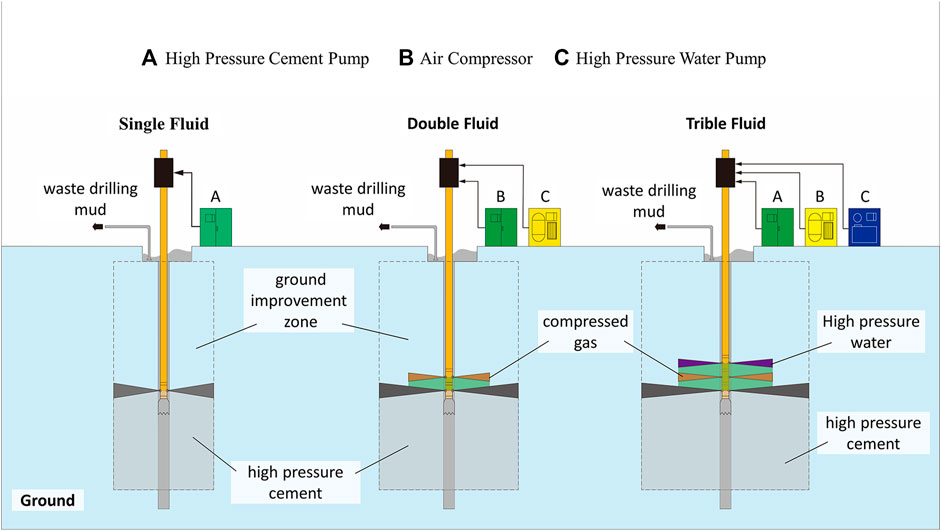
FIGURE 2. Classification of high-pressure jet grouting piles.
Nowadays, shallow buried tunnels of highways gradually adopt high-pressure jet grouting pile construction technology for surface soft surrounding rock reinforcement and achieve good results. Wang et al. (2017) used high-pressure jet grouting piles for soft foundation reinforcement in the combined bridge-tunnel section of the Hong Kong–Zhuhai–Macao Bridge, with a replacement rate of 31.4%–40.3% in the reinforced area and a water–cement ratio of 0.8. The in situ field test proved that the high-pressure jet grouting pile composite foundation can effectively improve the stratum elastic mode and reduce the permeability of the stratum. Ren (2009) applied high-pressure jet grouting piles to the construction of shallow buried tunnels in saturated water-bearing layers, using a slurry pressure of 20–23 MPa, a rotation speed of 10–15 r/min, and a lifting speed of 10–15 cm/min. It was found that the quality of high-pressure jet grouting piles is greatly affected by adverse geology, and on-site rotary tests should be conducted before large-scale rotary spraying to achieve a better reinforcement effect. Que (2009) studied high-pressure jet grouting piles for ground reinforcement in shallow buried tunnels with sandy soil, using a cement dosage of 400 kg/m, a water–cement ratio of 0.8, and an unconfined compressive strength of 1.5 MPa, which shows that the piles have the effect of improving the force form, improving the effect of water stopping in the ground, and speeding up the construction of the tunnel. Ou et al. (2016) compared four shield tunnel ground reinforcement schemes by numerical analysis, and the study showed that high-pressure jet grouting piles can effectively play the role of water isolation, reduce ground loss, and reduce surface settlement.
Previous studies on the field tests and applications of high-pressure jet grouting pile reinforcement in ultra-shallow buried tunnels with strong weathering strata are rare. In this paper, based on the ultra-shallow buried tunnel construction of the new Wu Tunnel as the engineering background, the innovation of the application and evaluation of the reinforcement effect of high-pressure jet grouting pile ground reinforcement technology in the ultra-shallow buried tunnel excavation in the strongly weathered stratum is studied through field tests and theoretical analyses, to provide some reference significant for the high-pressure jet grouting pile in the ultra-shallow buried tunnel ground reinforcement in the strongly weathered stratum.
The new Wu tunnel is a separate tunnel; the total length of the tunnel is 2,500 m, the slope of the whole tunnel is −2.3%, and the maximum depth of the tunnel is about 218.4 m. The tunnel body crosses two ultra-shallow buried sections; the ultra-shallow buried tunnel left line longitudinal section is shown in Figure 3. The main influence range of the first section is ZK84 + 450–ZK84 + 476 (the left line tunnel), and K84 + 453–K84 + 475 (the right line tunnel). The left line exposed top is about 1 m, and the minimum cover layer of the right line is about 2 m thick, with surface water development and ditch development; the main impact area of the second section is ZK84 + 628 to ZK84 + 829 (the left line tunnel) and K84 + 644 to K84 + 795 (the right line tunnel). The surface above the tunnel is undulating, mostly paddy fields, large basin area, and some sections are ditches; multiple reservoirs, wells and houses are distributed in the upstream shallow buried section of the tunnel.
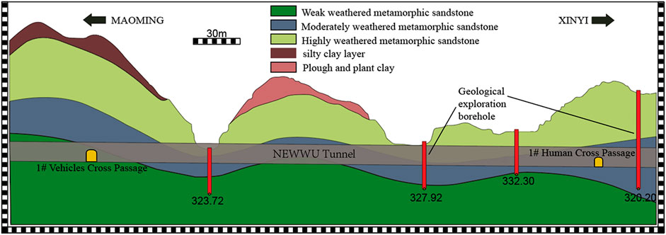
FIGURE 3. Longitudinal section of the left line.
The stratigraphic lithology of the tunnel site area is Quaternary slope residual powder clay, metamorphic sandstone of the Yuan Dynasty Yunkai Rock Group, Garidonian granite, and its weathering layer. From the surface to the bottom of the tunnel, the rocks are, from top to bottom, cultivated soil, chalky clay, silty chalky clay, fine sand, chalky clay, and strongly weathered metamorphic sandstone, and below is medium-weathered metamorphic sandstone (below the bottom of the tunnel). The groundwater level in the section is located at the original ground level, with surface water flowing all year round. The geological longitudinal distribution of the layers is shown in Table 1.
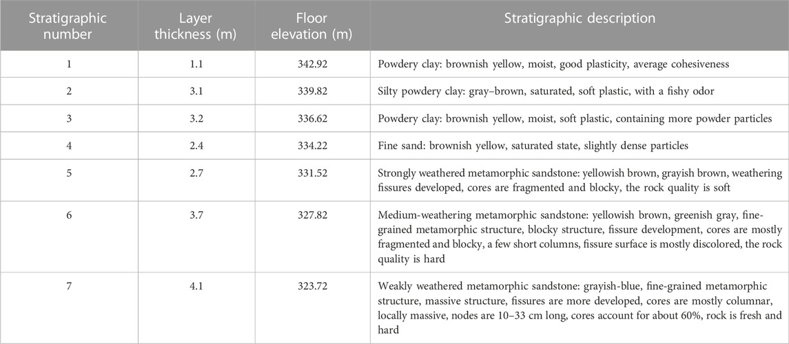
TABLE 1. Geological distribution of tunnel stratigraphy.
The tunnel (ZK84 + 450–ZK84 + 476 and K84 + 453–K84 + 475) construction method adopts the single sidewall excavation method, the composite lining of XS-Va type, the double-layer small conduit for overrun support, small conduit spacing of 0.4 m, single length 4 m, 37 per ring, longitudinal 2.4 m/ring, a φ25 hollow grouting anchor rod for initial support, single length 3.5 m, spacing 100*60 (circumferential*longitudinal) cm, I20a I-beam spacing 0.6 m, locking foot anchors φ22 pill roll anchors, single length 3 m, and 8 per ring. The second lining adopts C30-reinforced waterproof concrete, with a thickness of 50 cm.
This experimental study conforms to the Highway Engineering Cement Test Code (JTG3420-2020) (Transport, 2005) to investigate the characteristics of the consolidation formed by using a high-pressure jet grouting pile. The cement soil slurry consists of four parts: water, cement, admixture, and soil body. The main factors affecting the consolidation performance of cement soil are cement strength grade, curing agent mixing ratio, maintenance age, soil parameters, and admixtures. In the test, the soil samples were used in a certain range of powder clay above the tunnel at the construction site, and the cement used to prepare the slurry was 42.5# normal silica cement with a compressive strength of 45.0 MPa at 28 d. The replacement rate of the high-pressure jet grouting pile used in the test was 0.34. The performance test of cement soil and the compressive strength test of specimens are shown in Figure 4.
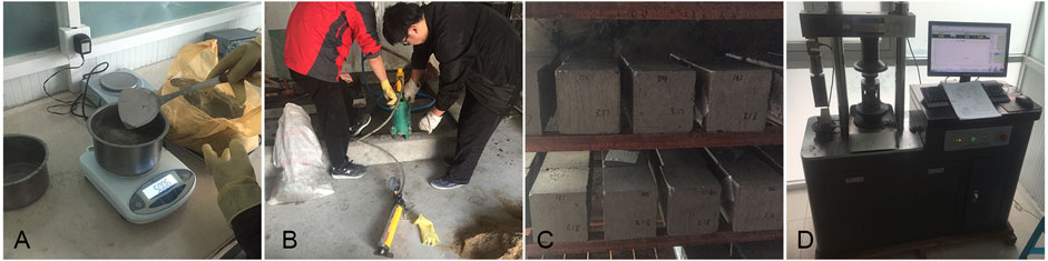
FIGURE 4. Test of the consolidation body properties. (A) Mix ratio test, (B) Water separation test rate, (C) Sample maintenance, (D) Compressive strength test.
According to the requirements of the high-pressure jet grouting pile, four cement soil types with water–cement ratios of 0.8, 1.0, 1.2, and 1.5 were modulated and mixed with the clay soil samples according to the replacement ratio of 0.34 test requirements (as shown in Figure 4A). The cement soil density, funnel viscosity, and water separation rate (as shown in Figure 4B) measured in this study are shown in Table 2. It can be seen that the slurry density decreases, the water separation rate increases, and the viscosity decreases as the water–cement ratio increases. Therefore, under the premise of satisfying the construction requirements and considering the stability of the slurry, the water–cement ratio should be small.
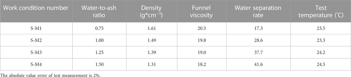
TABLE 2. Cement soil property test results.
The soil samples at the site of the compressive strength test were mixed with cement paste materials of different proportions, and the test blocks were molded with a cube with a side length of 7.00 cm. After the molds were removed, the compressive strength test was carried out after curing for 28 days at standard conditions (20°C ± 1°C and RH ≥ 95%) according to GB/T 50082-2009 (Lu et al., 2022) (as shown in Figures 4C, D). From the compressive strength test results shown in Table 3, it can be seen that under the conditions of a certain water–cement ratio, the consolidation strength increases when the cement increases; under a certain cement content, the consolidation strength decreases when the water–cement ratio increases. The sudden change in the strain–stiffness curve of the load-displacement curve of the axial compression test marks the development of cracks in the consolidated sample (Gao et al., 2018). The on-site high-pressure consolidation strength can be analyzed by the inlet weight, return weight, and sand content of the return slurry. The high-pressure consolidation strength can be determined by the inlet weight, return weight, and sand content of the slurry, and consolidation strength of the return slurry. Concerning the indoor test results for preliminary estimation, the parameters can be adjusted during the construction test.
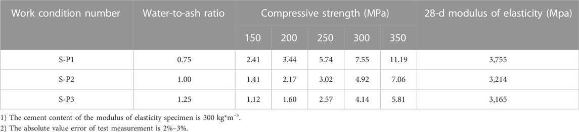
TABLE 3. Mechanical properties of solid test results.
The cement soil with different water–cement ratios was mixed with the base material and then molded with a 15 cm × 30 cm test mold. The mold was removed after 48 h of wet maintenance on the surface. Test specimens were moved to the maintenance room and taken out until 28 d and loaded on the testing machine until destruction while measuring the deformation relative to both sides. This test provides a set of useful test data for evaluating the effect of stratum reinforcement, the static load-bearing capacity of the foundation, and the stability analysis of tunnel excavation (Gao et al., 2022). The results of the spring mold test are shown in Table 3, and the stress–strain curve is shown in Figure 5.
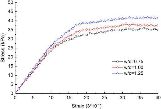
FIGURE 5. Stress–strain curve of the solid body.
The soil samples collected in the field were mixed with cement soil and molded with a 7.5 cm upper, 8.5 cm lower, and 3 cm high test mold, and after demolding, they were maintained in the maintenance room until 28 d of age and tested on the mortar impermeability meter to determine the permeability coefficient at the constant head, and the results are shown in Table 4. The test results show that the permeability of the consolidation body increased with increasing water–cement ratio at the same room temperature.
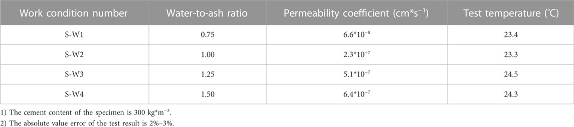
TABLE 4. Specimen seepage resistance test results.
The construction process of high-pressure jet grouting piles is complex, and the geological conditions and hydrology of the shallow buried section of the reinforced tunnel are complicated, so field trial piling tests must be carried out to determine the key technical indicators to ensure the reinforcement and impermeability effects and to guarantee the safety and speed of the tunnel construction. To test the piling effect of high-pressure jet grouting piles, and the ground reinforcement, piling load tests, and pile core drilling tests were carried out.
The spray pressure needs to be considered in terms of the compactness, compressive strength, and scour resistance of the soil. The lifting speed has a great influence on the quality and diameter of the pile consolidation body. The spray speed and the lift speed are two correlated parameters. According to the construction experience, single-tube spin spray pile lifting heights per revolution ranges from 0.5–1.25 mm. To satisfy the construction parameters that the soil within 0.25 m can be subjected to five jet impacts, we selected 20, 22, and 25 r/min as test parameters. The test is arranged with 18 high-pressure jet grouting pile test piles, consisting of nine groups of test piles (three piles in each group). The single-pile static load test and drill core sampling test were conducted, and the specific design of the working conditions is shown in Table 5. The test piles follow the positive triangular arrangement, the standard working conditions of the pile diameter of 0.5 m, and spacing of 1.5 m. The standard test pile has a rotating speed of 20 r/min, an injection pressure of 25 Mpa, and a mechanical lifting speed of 25 cm/min. The total length of the pile is about 10 m.
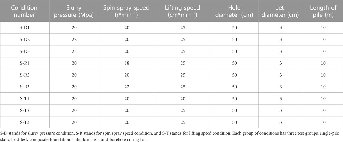
TABLE 5. Rotary pile surface test condition design table.
The static load test equipment includes one set of RSM-JCIII static load test system, one set of 300T jack, one set of pressure transducers, and four sets of displacement transducers. The load value is measured using the pressure transducer and the pile settlement value is recorded using displacement meters symmetrically distributed on the load plate. The displacement meter is fixed by a magnetic base to the reference beam, and the distance between the reference amount and the center point of the load plate is 2.5 m. The schematic diagram of pile static loading is shown in Figure 6.
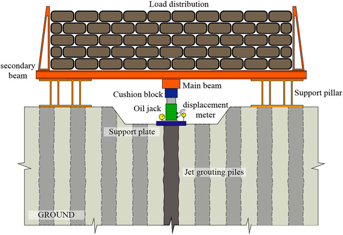
FIGURE 6. Pile static load schematic diagram.
The static load test adopts the graded load settlement relative stability method. The maximum design test load is 300 kN divided into 10 grades, and each grade loading value (taking 1/10 of the design limit load) is 30 kN. After the test loads to the expected maximum load, the loading is terminated. The single-pile load test uses a round bearing plate with a diameter of 0.5 m. After the test, the test pile body is excavated to check the integrity of the pile and the slurry situation, as well as the bearing capacity. The core test is conducted by the conventional coring method according to the construction specification.
The parameters of the high-pressure jet grouting pile need to be combined with the project geological conditions and the empirical data of similar projects should be referred to for verification, combined with the field piling test (Pan et al., 2021). Ultra-shallow buried tunnel ground reinforcement should also consider tunnel design requirements, minimum depth of burial, and construction safety (Li, 2004). The pile load settlement curves under different test conditions are shown in Figure 7. The statistics of the single-pile bearing capacity test results are shown in Table 6.
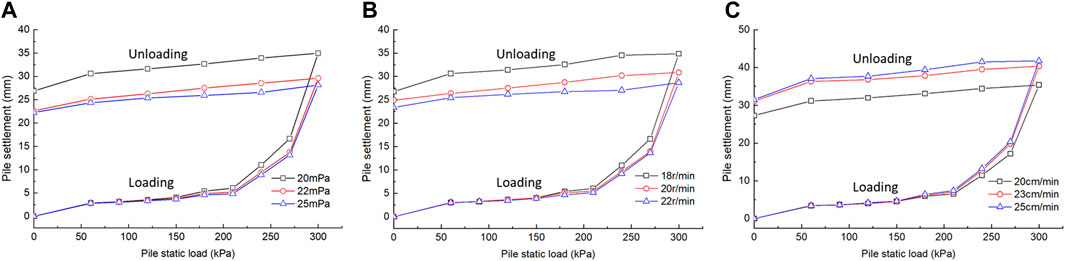
FIGURE 7. Settlement curve of the single pile under different test conditions. (A) Different slurry pressure conditions, (B) Different rotary speed conditions, (C) Different lifting speed conditions.
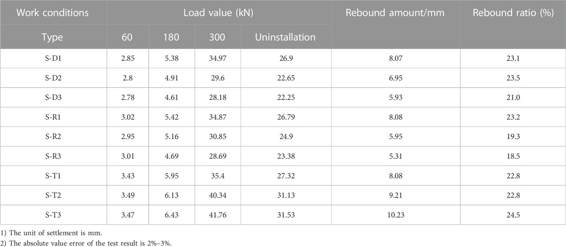
TABLE 6. Statistics of static load test data of the single pile.
The three groups of working conditions, S-D1, S-D2, and S-D3, are the test piles of high-pressure jet grouting piles under different slurry pressure conditions. Under the requirements of the monopile static load test, incremental loading is carried out until the design load of 300 kPa is reached. From Figure 7A, it can be seen that under the first loading condition of a static load of 30 kPa, the cumulative settlement value of the pile top is 2.85 mm; when the static load is loaded to the 5th load level of 180 kPa, the cumulative settlement value of the pile top is 5.38 mm; the maximum cumulative settlement value of the pile top is 34.97. After reaching the maximum design load value and unloading, the residual settlement value of the pile top is 26.9 and the rebound amount is 8.07 mm s-D2. The cumulative settlement at the top of the pile is 2.80 mm at the first load, 4.91 mm at the fifth load, and 29.6 at the maximum load. After unloading, the residual settlement of the pile top was 22.25 and the rebound was 5.93 mm.
From the test results, it can be found that the slurry pressure has a significant effect on the static load-bearing capacity of the monopile; the higher the slurry pressure, the lower will be the cumulative settlement value of the monopile under the same static load condition. When the slurry pressure was increased from 20 Mpa to 22 Mpa, the cumulative settlement value of the single pile under the maximum design load condition was reduced by 5.37 mm and the rebound was reduced by 1.12 mm. When the slurry pressure was increased from 22 Mpa to 25 Mpa, the cumulative settlement value of the single pile under the maximum design load condition was reduced by 1.42 mm and the rebound was reduced by 1.02 mm, and the cumulative settlement value increased by a smaller amount. The amount of change in rebound is the same.
The three groups of working conditions, S-R1, S-R2, and S-R3, are test piles of high-pressure jet grouting piles under different rotary speed conditions. The test results are shown in Figure 7B. The cumulative settlement at the top of the pile for S-R1 was 3.02 mm at the first load; the maximum cumulative settlement at the top of the pile was 34.87 at the fifth load stage; after reaching the maximum design load, the pile was unloaded to 0 at 60 kPa step-by-step; after completion of unloading, the residual settlement at the top of the pile was 26.79 and the rebound was 8.08 mm. After unloading, the residual settlement at the top of the pile was 24.9, with a rebound of 5.95 mm. The residual settlement value of the pile top after unloading is 23.39 and the rebound is 5.31 mm.
From the test results, it can be found that when the spin spray speed increased from 18 to 20 r/min, the cumulative settlement value of the single pile under the maximum design load condition was reduced by 4.02 mm, and the amount of rebound was reduced by 2.13 mm. When the spin-spray speed increased from 20 to 22 r/min, the cumulative settlement value of the single pile under the maximum design load condition was reduced by 2.16 mm, and the amount of rebound was reduced by 0.64 mm. The rotational speed of rotary spraying has a significant effect on the static load-bearing capacity of the single pile; the larger the rotational speed of rotary spraying, the lower will be the cumulative settlement value of the single pile under the same static load conditions. With the increase in the rotational speed of rotary spraying, the rate of change of the cumulative settlement value of the single pile decreases, and the rate of change of the rebound volume also decreases.
The three groups of working conditions, S-T1, S-T2, and S-T3, are the test piles of High-pressure jet grouting piles under different lifting speed conditions. The test results are shown in Figure 7C, from which it can be seen that the cumulative settlement at the top of the pile at the first load was 3.43 mm for S-T1, 5.95 mm at the fifth load level, and 35.40 for the maximum cumulative settlement at the top of the pile. After unloading, the residual settlement at the top of the pile is 31.13, with a rebound of 9.21 mm. The residual settlement value after unloading is 31.53, and the rebound is 10.23 mm.
From the test results, it can be found that when the lifting speed increased from 20 cm/min to 25 cm/min, the cumulative settlement value of the monopile under the maximum design load increased by 4.94 mm, and the rebound increased by 1.13 mm. When the lifting speed increased from 25 cm/min to 30 cm/min, the cumulative settlement value of the monopile under the maximum design load increased by 1.42 mm and the rebound increased by 1.02 mm. The rotational speed of the rotary spray has a significant effect on the static load-bearing capacity of the single pile; the higher the slurry pressure, the higher will be the cumulative settlement value of the single pile under the same static load condition. With the increase of the lifting speed, the increase of the cumulative settlement value decreases, and the rate of the change of rebound remains the same.
After the test pile, the high-pressure jet grouting pile was completed in 14 days and the test pile was drilled core. The high-pressure jet grouting pile coring condition is shown in Figure 8A. A borehole depth of 1.5 m–7.5 m is a mixed layer of water and soil, grayish white, more uniform in color, with bubbles. Through the analysis of high-pressure jet grouting pile coring, it is found that the height of the mud spillover is basically above the strongly weathered metamorphic sandstone layer, and the stratum where the mud spillover is located is mainly a loose powdered clay layer and sandy layer. After the pile excavation, it was found that the maximum mud spillover height at the top of the rotary pile was 0.8 m, and the cement soil strength was not high. The hydro clay of the pile was more uniform, and the strength was high and brittle. After the test pile construction is completed, the pile body is sampled using the drilling core. It is found that the quality of the pile is good through drilling, and the pile diameter is up to 60–75 cm (see Figure 8B), to meet the design requirements. The piles played a role in consolidating the weak soil layer above the tunnel vault, to create conditions for the safe excavation of the shallow buried section of the tunnel.
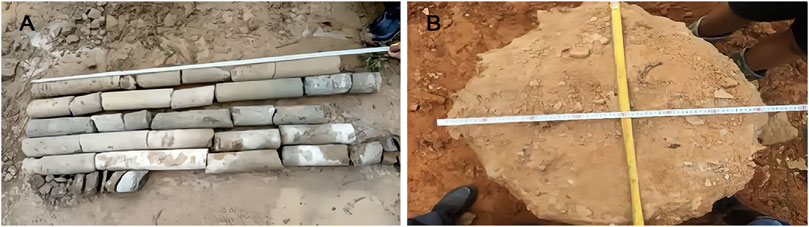
FIGURE 8. Drill core sampling of the high-pressure jet grouting pile. (A) Drill core sampling, (B) The pile diameter.
The sections ZK84 + 645 to ZK84 + 820 (the left line) and K84 + 650 to K84 + 705 (the right line) are the test sections of the tunnel stratum reinforcement. The reinforcement test of a high-pressure rotary jet grouting pile is carried out on an ultra-shallow tunnel, and the surrounding rock integrity, deformation around the tunnel, the support structure stress, and permeability are monitored to evaluate the reinforcement effect of the tunnel.
Before the test, the surface vegetation, rooted soil, and flow-plastic silt were cleaned up, and the silt was excavated and refilled. In the test, the grouting pressure of the high-pressure rotary jet grouting pile is 22–24 mpa, the lifting speed is 18–22 cm/min, the rotation speed is 20 r/min, the pile spacing is 1.5 m, and the water–cement ratio of the grouting pile is 1:1. After the reinforcement of the piles, the shallow buried section is constructed in the construction sequence. The process of tunnel high-pressure jet grouting pile reinforcement is shown in Figure 9.
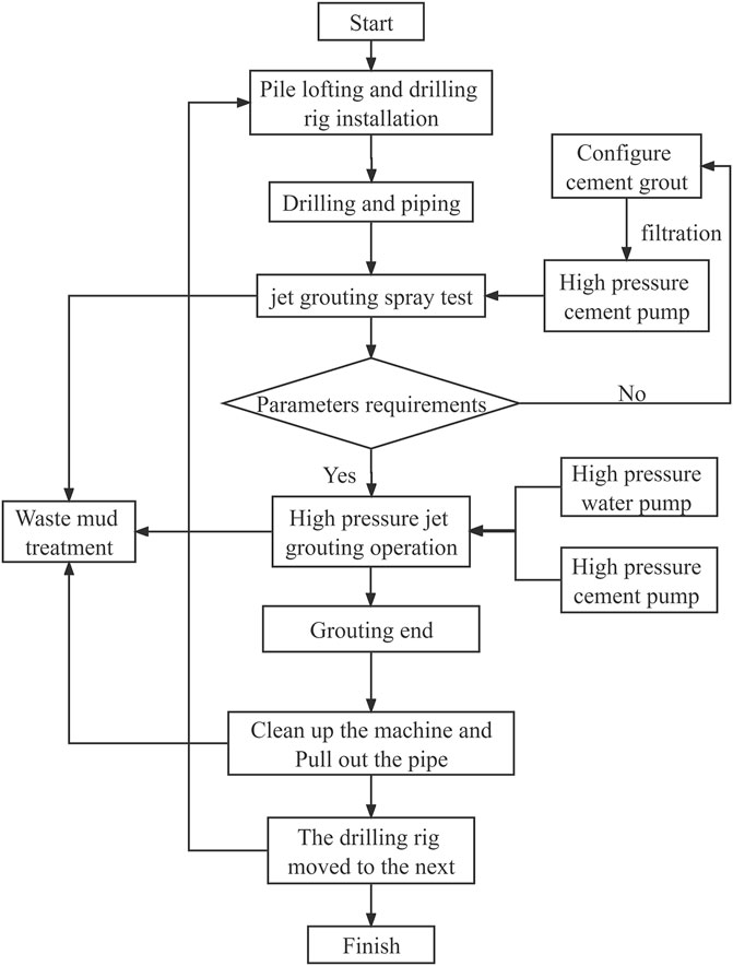
FIGURE 9. Flow chart of tunnel reinforcement.
The reinforcement range of the high-pressure rotary jet grouting pile is 6 m on both sides of the tunnel, and the pile spacing is 1 m. The piles are reinforced to the depth of the tunnel invert, and the length of the pile is 10–13 m, depending on the length of the pile passing through the fully weathered soft layer. The high-pressure jet grouting pile site plan layout is shown in Figure 10. The cross-section of the pile reinforcement range is shown in Figure 11.
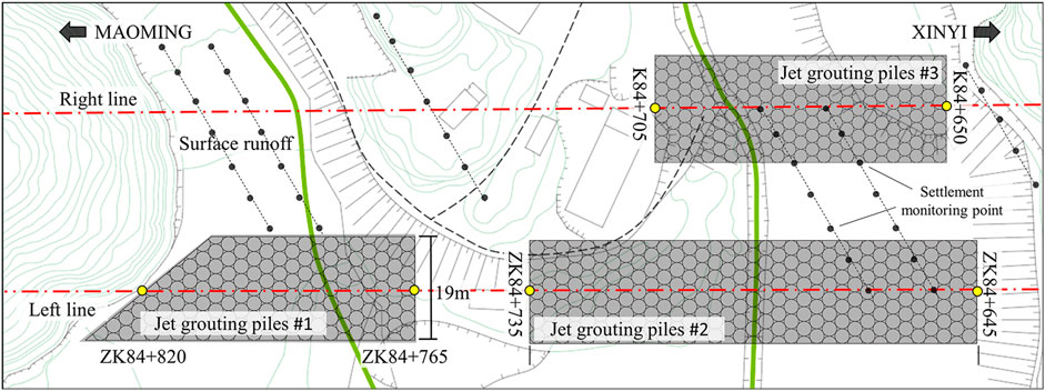
FIGURE 10. Layout plan of the high-pressure jet grouting pile.
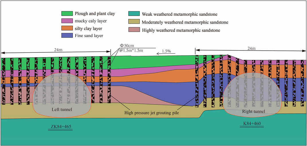
FIGURE 11. Cross section of the pile reinforcement range.
The tunnel structure of the shallow buried section is a composite lining structure, including two parts: primary lining and secondary lining (Lu et al., 2022a). In the early stage of construction, the primary lining subjected to a large formation slack load is usually implemented to stabilize the ground (Qiu et al., 2019). In order to ensure construction safety, the tunnel excavation construction is carried out by strengthening the tunnel surrounding rock with the high-pressure rotary jet grouting pile. Tunnel excavation of the test section after reinforcement of the high-pressure jet grouting pile is shown in Figure 12. The surrounding rock between the piles has a high cement content and well integrity with a compaction effect between the piles. Compared with the soil outside the depth range of the high-pressure jet grouting pile, the strength of the piles is greatly improved. As a result of high-pressure jet grouting pile ground reinforcement, the pile body plays a supporting role for the soil layer, limiting the lateral displacement of the soil layer, and the tunnel lateral convergence is small, indicating that the high-pressure jet grouting pile anti-extrusion effect is obvious. The high-pressure rotary jet grouting pile can improve the integrity of the surrounding rock, and the self-stability ability to surround rock can be effectively played during tunnel excavation, indicating that the high-pressure rotary jet grouting pile has played a good reinforcement role.
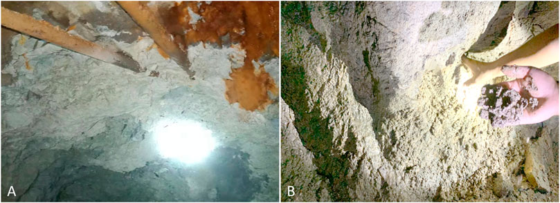
FIGURE 12. Tunnel arch after excavation. (A) Tunnel vault, (B) Tunnel arch foot.
According to the on-site monitoring results, in the early stage of tunnel support, the surrounding rock pressure is released quickly and finally stabilizes at about 6 KPa, within the reasonable range of treatment. The stress of the steel arch developed rapidly in the early stage and gradually balanced in the later stage. The maximum internal force of the arch was stable at 0.3 Mpa, which was within the allowable design range. The surface settlement is stable and the settlement value is within the allowable range of the design; the pore pressure is stable at 5 KPa. Comprehensive analysis shows that the stress and deformation of the support structure in the shallow buried section are allowable after reinforcement of a high-pressure jet grouting pile, and the pore water pressure of formation is greatly reduced. The high-pressure jet grouting pile can effectively reduce the stress and deformation of the support structure in shallow buried sections and reduce the pore water pressure of the surrounding rock. According to the excavation condition, there were slight water stains on the initial supporting local surface of the upper bench and the whole surface was relatively dry (see Figure 13A). The groundwater mainly flows into the tunnel on both sides of the middle step and is discharged from the drainage ditch (see Figure 13B). To better show the lining water leakage water distribution, the lining surface scanning can be carried out using a 3D laser (Li et al., 2021). After the reinforcement of the high-pressure rotary jet grouting pile, the top of the ultra-shallow tunnel is stable after excavation, and the cracks between surrounding rocks are filled and consolidated by cement slurry. The strength and integrity of the surrounding rock are improved. The water seepage on the surface of the upper step is small, and the groundwater flows out along the arch feet on both sides, and the pile body plays a certain role in the water stop.
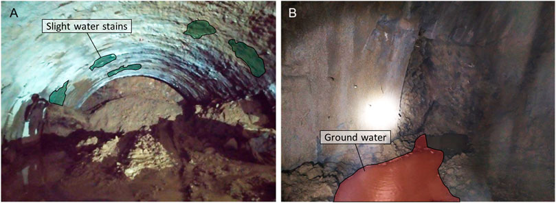
FIGURE 13. Water seepage in tunnel lining. (A) Tunnel arch, (B) tunnel side wall.
Based on the mechanical property test of the grouting material, the static load-bearing capacity of the test pile, and field application, this paper studies the application effect of a high-pressure rotary jet grouting pile in the reinforcement of an ultra-shallow tunnel in a strongly weathered stratum. The conclusions are as follows:
1) The compressive strength, elastic modulus, and seepage resistance of the cement soil are related to the water–cement ratio. The permeability of the consolidation body increases with increasing water–cement ratio under the constant head; under a certain water–cement ratio, the strength increases with increasing cement content.
2) Field piling tests were carried out to determine the key technical indicators to ensure the reinforcement and impermeability effects. The static load test results of a single pile show that the greater the slurry pressure, the lower the cumulative settlement value, the greater the rotational speed, the lower the cumulative settlement value of the single pile, the greater the slurry pressure, and the lower the cumulative settlement value.
3) The height of mud spillover is basically above the strongly weathered metamorphic sandstone layer. The maximum mud spillover height at the top of the rotary pile is 0.8 m. The pile body is uniform with high strength and is brittle. The pile diameter reaches 60–75 cm, which meets the design requirements.
4) After the reinforcement of the high-pressure jet grouting pile, the cracks in the surrounding rock are filled and consolidated by cement slurry. The strength and integrity of the surrounding rock are improved. The water seepage on the surface of the upper step is small, and the groundwater flows out along the arch feet which means that the pile body plays a certain role in the water stop. The high-pressure rotary jet grouting pile has played a good reinforcement role.
The original contributions presented in the study are included in the article/Supplementary Material; further inquiries can be directed to the corresponding authors.
PL: conceptualization, methodology, analysis, and writing; WQ and FL: validation, resources, and funding acquisition; XH, HL, and ZH: experiment design and data collection; and ZC, LL, and YW: investigation, supervision, and review editing. All authors read and agreed to the published version of the manuscript.
This work was supported by the Natural Science Foundation of Sichuan (2022NSFSC1025), the National Natural Science Foundation of China (51991395, 52178395), and the National Key R&D Program of China (2017YFC0806000).
Author HL was employed by the company Anhui Transport Consulting & Design Institute Co., Ltd.
The remaining authors declare that the research was conducted in the absence of any commercial or financial relationships that could be construed as a potential conflict of interest.
All claims expressed in this article are solely those of the authors and do not necessarily represent those of their affiliated organizations, or those of the publisher, the editors, and the reviewers. Any product that may be evaluated in this article, or claim that may be made by its manufacturer, is not guaranteed or endorsed by the publisher.
Brandsttter, C., Lackner, R., Pichler, C., and Mang, H. A. (2001). Computational mechanics–new Frontiers for the new millennium, 3–15. doi:10.1016/B978-0-08-043981-5.50007-9 Application of jet grouting in NATM tunneling - ScienceDirect
Chen, L. J., Liang, B., and Wang, G. (2013). Study of excavation method for shallow-buried subway station tunnels with super-large section. Chin. J. Undergr. Space Eng. 9 (4), 6.
Cui, S. H., Wu, H., Pei, X., Yang, Q. W., Huang, R. Q., and Guo, B. (2022). Characterizing the spatial distribution, frequency, geomorphological and geological controls on landslides triggered by the 1933 Mw 7.3 Diexi Earthquake, Sichuan, China. Geomorphology 403, 108177. doi:10.1016/j.geomorph.2022.108177
Davis, E. H., Gunn, M. J., and Mair, R. J. (1981). Stability of shallow tunnels and underground openings in cohesive material. Int. J. Rock Mech. Min. ences Geomechanics Abstr. 18 (3), 51. doi:10.1016/0148-9062(81)91080-9
Gao, M. B., Cui, S. H., Li, T. B., Ma, C., Wu, Z., Zhang, Y., et al. (2022). Investigation on the expression ability of a developed constitutive model for rocks based on statistical damage theory. Lithosphere 2021 (7), 9874408. doi:10.2113/2022/9874408
Gao, M. B., Li, T. B., Meng, L. B., Ma, C., and Xing, H. (2018). Identifying crack initiation stress threshold in brittle rocks using axial strain stiffness characteristics. J. Mt. Sci. 15 (6), 1371–1382. doi:10.1007/s11629-018-4847-z
Hasan, M. F., and Canakci, H. (2022). An investigation of geomechanical and microstructural properties of full-scale jet grout column constructed in organic soil. Arab. J. Sci. Eng. 47 (4), 4605–4621. doi:10.1007/s13369-021-06189-z
Hu, Q. F., and Qin, J. B. (2013). Statistical analysis on accidents of subway tunnel construction from 2003 to 2011 in China. Chin. J. Undergr. Space Eng. 9 (3), 6.
Li, H. J., He, Y. S., Xu, Q., Deng, J. H., Li, W., and Wei, Y. (2022). Detection and segmentation of loess landslides via satellite images: A two-phase framework. Landslides 19 (3), 673–686. doi:10.1007/s10346-021-01789-0
Li, P. P., Qiu, W. G., Cheng, Y. J., and Lu, F. (2021). Application of 3D laser scanning in underground station cavity clusters. Adv. Civ. Eng. 2021, 1–12. doi:10.1155/2021/8896363
Li, P., Qiu, W., Lu, F., Yang, Q., Chen, Z., Li, L., and Deng, Z. (2021). Quasi-static test study of tunnel with resistance-limiting shock absorption layer in high-intensity seismic. Front. Earth Sci. doi:10.3389/feart.2022.1029929
Li, X. J. (2004). Analysis of calculation methods for bearing capacity and settlement of high-pressure chemical churning pile composite foundation. Rock Soil Mech. 25 (9), 4. doi:10.3969/j.issn.1000-7598.2004.09.032
Lu, F., Li, P. P., Zheng, Y. C., and Qiu, W. G. (2022). Experimental investigation on the mechanical performance of retrofitted cracked linings with mesh-bolts and plate-bolts. China J. Highw. Transp. 35 (5), 128. doi:10.19721/j.cnki.1001-7372.2022.05.012
Lu, F., Wang, H. Y., Wang, L. C., Zhao, K., and Zhang, J. R. (2022a). Degradation law and service life prediction model of tunnel lining concrete suffered combined effects of sulfate attack and drying–wetting cycles. Materials 15 (13), 4435. doi:10.3390/ma15134435
Nikbakhtan, A. H. A. N. G. A. R. I., Rahmani, , and Rahmani, N. (2010). Estimation of jet grouting parameters in Shahriar dam, Iran. Min. Sci. Technol. 20 (3), 472–477. (English Edition. doi:10.1016/S1674-5264(09)60228-3
Nikbakhtan, B., and Osanloo, M. (2009). Effect of grout pressure and grout flow on soil physical and mechanical properties in jet grouting operations. Int. J. Rock Mech. Min. Sci. (1997). 46 (3), 498–505. doi:10.1016/j.ijrmms.2008.10.005
Ou, Y. l., Yang, S. f., and Zhang, D. M. (2016). Subgrade settlement analysis in shield tunnel construction process using high-pressure rotary jet grouting pile joint with sleeve valve barrel grouting reinforcement method. Railw. Surv., 64–67. doi:10.19630/j.cnki.tdkc.2016.04.021
Pan, H. L., Qian, H. P., Cai, Z., Lan, Y., Guo, X., and Hong, Y. (2021). Field test of high pressure jet grouting pile for strengthening highly sensitive soft soil foundation. J. Ground Improv. 3 (1), 5.
Qiu, W., Lu, F., Wang, G., Huang, G., Zhang, H., Zhang, Z., et al. (2019). Evaluation of mechanical performance and optimization design for lattice girders. Tunn. Undergr. Space Technol. 87, 100–111. doi:10.1016/j.tust.2019.02.008
Que, S. H. (2009). Application of high pressure spinning jetting pile in consolidating surrounding rock in tunnel. Technol. Highw. Transp. (2), 4. doi:10.3969/j.issn.1009-6477.2009.02.035
Ren, X. W. (2009). Tests on high-pressure whirly-sprayed piles in construction of shallow tunneh with mining method at dynamic watery saturated gravel layer and diseussion on its application. Railw. Stand. Des. (7), 5. doi:10.3969/j.issn.1004-2954.2009.07.028
Wang, S., Zhao, M., and Lin, Z. (2009). Summary of common geologic hazards during highway tunnel construction. Highw. traffic Technol. (1), 102–106. doi:10.3969/j.issn.1009-6477.2009.01.029
Wang, Y. N., Jiang, B. S., Yu, J., Gao, C., and Fang, D. Y. (2017). In-situ experiment on composite foundation of high pressure jet grouting piles of Hong Kong-Zhuhai-Macau Bridge. Chin. J. Rock Mech. Eng. 36 (6), 8. doi:10.13722/j.cnki.jrme.2016.1005
Zhang, C. P., Han, K. H., Zhang, D. L., Li, H., and Cai, Y. (2014). Test study of collapse characteristics of tunnels in soft ground in urban areas. Chin. J. Rock Mech. Eng. 33 (12), 10. doi:10.13722/j.cnki.jrme.2014.12.008
Zhang, J., Chen, Y., Chen, T., Mei, Z., Liu, Z., Wang, F., et al. (2018). Law and Characteristics Analysis of Domestic Tunnel Construction Accidents from 2006 to 2016[J]. Mod. Tunn. Technol. 55 (3), 10–17. doi:10.13807/j.cnki.mtt.2018.03.003
Keywords: high-pressure jet grouting pile, ultra-shallow buried tunnel, strongly weathered stratum, stratum reinforcement, experimental research
Citation: Li P, Huang X, Lu F, Qiu W, Liu H, Li L, Wang Y, Chen Z and He Z (2023) Experimental investigation on the reinforcement of a high-pressure jet grouting pile for an ultra-shallow tunnel in a strongly weathered stratum. Front. Earth Sci. 10:1040461. doi: 10.3389/feart.2022.1040461
Received: 09 September 2022; Accepted: 25 November 2022;
Published: 25 January 2023.
Edited by:
Chengyi Pu, Central University of Finance and Economics, ChinaReviewed by:
Xinlei Zhang, Nanjing Tech University, ChinaCopyright © 2023 Li, Huang, Lu, Qiu, Liu, Li, Wang, Chen and He. This is an open-access article distributed under the terms of the Creative Commons Attribution License (CC BY). The use, distribution or reproduction in other forums is permitted, provided the original author(s) and the copyright owner(s) are credited and that the original publication in this journal is cited, in accordance with accepted academic practice. No use, distribution or reproduction is permitted which does not comply with these terms.
*Correspondence: Feng Lu, ZmVuZ2x1MDkwMUBmb3htYWlsLmNvbQ==; Zhihao He, aGV6aGloYW9AbWFpbC54aHUuZWR1LmNu
Disclaimer: All claims expressed in this article are solely those of the authors and do not necessarily represent those of their affiliated organizations, or those of the publisher, the editors and the reviewers. Any product that may be evaluated in this article or claim that may be made by its manufacturer is not guaranteed or endorsed by the publisher.
Research integrity at Frontiers
Learn more about the work of our research integrity team to safeguard the quality of each article we publish.