 Xiaojia Ji
 Qingling Wu
- 1Intelligent Safe Collaborative Innovation Center, Zhejiang College of Security Technology, Wenzhou, China
- 2School of Civil Engineering and Architecture, Wenzhou Polytechnic, Wenzhou, China
In practical engineering, slopes subjected to local loads, like footings of buildings, are common. This paper aims to give an insight into the effect of seismic force on the stability of locally loaded slopes. Numerical methods can be used to study this problem, but they require much computational time. Contrarily, limit analysis method is an approach to perform slope stability analysis with high computational efficiency. Thus, an accurate approach in mechanical points is proposed for this problem based on limit analysis method herein. In the framework of limit analysis, existing research about this problem used a kinematically translational velocity field. However, the velocity field of the locally loaded slope at failure is proved to be rotational possibly. Thus, to fill this gap, a 3D rotational velocity field is employed herein to obtain limit loads on the slope top, which improves the existing upper-bound solutions obtained by using the translational velocity field. The particle swarm optimization algorithm and the Nelder-Mead simplex algorithm are employed to search the global minimum of the upper-bound estimation of the limit load. Parametric analysis is performed and it shows that the limit load increases with the increase of a/H or the internal friction angle φ but decreases as the slope angle β or the length-to-width ratio (L/t) of the local load increases. Furthermore, the limit load is found to decrease with the increase of the seismic coefficient
Introduction
It is common to construct infrastructures, such as a building or a road, on the top of slopes in engineering practice. In this circumstance, they are prone to collapse when the stability of the slope is threatened. In some regions of the world, there are frequent seismic activities that have great adverse effects on slope stability. When an earthquake occurs, the buildings on the top surface of slopes are likely to collapse, resulting in huge losses (Song et al., 2021a; Song et al., 2021b; Song et al., 2021c; Song et al., 2021d). Thus, it is important to study the effect of seismic activities on the stability of locally loaded slopes.
Many papers have been devoted to the stability analysis of locally loaded slopes using various approaches. The slice method of limit equilibrium was used to study this problem by many scholars (Bishop, 1955; Morgenstern and Price, 1965; Spencer, 1967; Acevedo et al., 2021; Jiang et al., 2021). Using the limit equilibrium method, Azzouz and Baligh (1983) conducted circular arc limit equilibrium analysis and gave a set of charts for clay slopes bearing strip and square footings. The limit equilibrium method was also employed to provide solutions and design charts for this problem by many other scholars (Meyerhof, 1957; Saran et al., 1989). Recently, the finite element method has been widely adopted. Georgiadis (2010) employed the finite element method to investigate the undrained bearing capacity of strip footings on the top surface of slopes. The finite element method combined with a linear programming was used to compute the rigorous upper bounds of the collapse load by Sloan (1989). Leshchinsky (2015) used the discontinuity layout optimization (DLO) approach to investigate the bearing capacity of a footing on the crest of a c-φ slope. The DLO approach was also employed by Zhou et al. (2018) to study the bearing capacity and failure mechanism of locally loaded slopes.
However, the limit equilibrium method requires hypotheses about the inter-slice force, which may reduce the theoretical rigor, and the numerical method requires much computational time, which is of low efficiency. Compared with the methods introduced above, limit analysis method is equipped with a rigorous mechanics basis and high calculation efficiency. Therefore, it is studied by many scholars in recent years. The upper bound theorem of limit analysis states that an upper bound estimation of the force which drives the slope to collapse can be obtained by equating the total external work rate to the internal energy dissipation rate computed in a kinematically admissible velocity field (He et al., 2012; Khezri et al., 2016; Qin et al., 2020; Xiao et al., 2020; Zhang et al., 2022). There are many kinematically admissible 3D velocity fields that can be used in the upper bound analysis of slope stability, for instance, the cylindrical and spherical mechanism (Baligh and Azzouz, 1975), the 3D multi-blocks failure mechanism (Michalowski, 1989), and the 3D rotational failure mechanism (Michalowski and Drescher, 2009; Pan et al., 2017). Besides these mechanisms above, the mechanical mechanism at failure of granular materials, like soils, can also be derived from the view of the soil particle rearrangement (Bai et al., 2019; Bai et al., 2022). For example, based on the soil particle rearrangement, Bai et al. (2021) proposed a new coupled thermo-hydro-mechanical mechanism. Michalowski (1989) performed a 3D stability analysis of locally loaded slopes and provided a set of upper-bound solution using the 3D translational multi-blocks failure mechanism. However, this issue has never been studied using a 3D rotational failure mechanism since this scenario may concern a rotational velocity field of slope at failure. Nevertheless, the recent numerical investigation performed by Li et al. (2019) showed that, at failure, the velocity field of the locally loaded slope is rotational rather than translational, and the velocity field given by Li et al. (2019) is reprinted in Figure 1. Therefore, it is necessary to perform a 3D seismic stability analysis of locally loaded slopes based on a 3D rotational velocity field, which is the gap of the present research. In the framework of limit analysis, the widely used 3D rotational velocity field is the 3D rotational failure mechanism proposed by Michalowski and Drescher (2009). Thus, the 3D rotational failure mechanism is employed herein to perform a stability analysis of slopes subjected to local loads on the top surface.
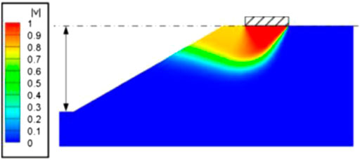
FIGURE 1. The rotational velocity field of the slope at failure [reprinted from Li et al. (2019)].
In the presented work, the 3D stability of slopes, subjected to seismic forces and local loads on the top surface, is investigated. The upper bound theorem of limit analysis is employed to calculate the critical limit load using the 3D rotational failure mechanism. To obtain the global minimum, the particle swarm optimization algorithm in combination with the Nelder-Mead simplex algorithm is adopted in searching for the least upper-bound solution. This paper extends the work of stability analysis of slopes subjected to local loads based on the 3D translational failure mechanism by Michalowski (1989) to that based on 3D rotational failure mechanism. To validate the present approach, the limit loads computed from the proposed approach are compared with the solutions of Michalowski (1989) and Zhou et al. (2018). A parametric analysis is provided at the end of this paper.
Problem description
As shown in Figure 2, a slope subjected to vertical local loads on the top surface is considered. The angle of the slope is denoted by
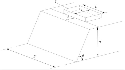
FIGURE 2. The 3D slope with a local load on the top surface.
In this problem, with the increase of a/t, the failure pattern will change from toe failure and face failure to Prandtl-type failure in which the failure surface extends to the bottom surface of slopes. The Prandtl-type failure cannot be studied by the 3D rotational failure mechanism. Therefore, only the toe failure and the face failure are in the consideration of this work, which is the limitation of the proposed method.
Upper bound seismic stability analysis of locally loaded slopes
Description of 3D rotational failure mechanism
The 3D rotational failure mechanism was firstly proposed by Michalowski and Drescher (2009) to study the stability of slopes. It is a classical 3D failure mechanism for slope stability analysis and inspired many subsequent researches (Gao et al., 2013; Yang and Pan, 2015). The geometry of the 3D rotational failure mechanism is sketched in Figure 3. It can be seen from Figure 3 that the shape of the 3D rotational failure mechanism is a curvilinear cone with an apex angle, a portion of which intersects the slope body (the sliding part). The symmetry plane of the failure mechanism contains two log-spirals whose equations are as follows
where OA=
where the expressions for
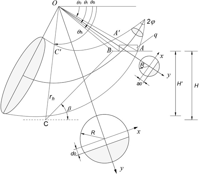
FIGURE 3. 3D rotational failure mechanism of slopes.
For the sake of the consistency with engineering practice, the 3D rotational failure mechanism is modified by splitting the halves of the 3D sliding body and placing a plane-strain insert between these two-halves, as shown in Figure 4. The width of the plane insert is denoted by b. It should be noted that the sum of the width of the two curved halves and the width of the plane insert, b, cannot exceed the slope width B. In addition, the width of the plane insert b is optimized together with the geometrical parameters determining the rotation center in the search for the best failure surface. In Figure 4, the local load q is symmetric about the symmetry plane of the failure mechanism. It should be noticed that the minimum width of the failure mechanism at the top surface of the slope, i.e., b, should not be smaller than the length of the local load, i.e., L, and, in other words, the constraint condition of
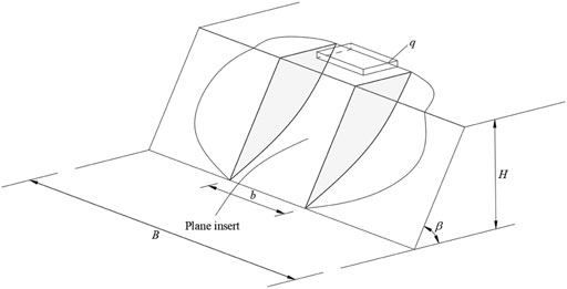
FIGURE 4. The modified 3D rotational failure mechanism with a plane insert.
Calculations of external work rate
To perform work rate calculations of external forces, a local coordinate system x-o-y is set up in the circular cross-section, as shown in Figure 3 and the original point o is the center of the circular cross-section. In this paper, the considered external forces include the gravity force, the seismic force and the vertical local load q on the top surface.
The work rate of gravity force includes two parts. The first one is the gravity force work rate done by the plane insert of the 3D rotational failure mechanism and the other one is that done by the two curved halves at the two ends of the failure mechanism. By integration, the expression of the gravity force work rate for the two curved halves is (Michalowski and Drescher, 2009):
where
Angle
After the integration about
The local load on the top of the slope is regarded as surface force whose work rate is obtained by performing integral over the intersecting region of the top of failure mechanism and the area where the load is distributed. For instance, when the failure mechanism gets through the right end point of the local load, as shown in Figure 3, the expression of the work rate of the local load is
The angle
where
In this paper, the seismic force is regarded as a static inertia force and characterized by a coefficient
After performing integration about
where the expressions for
The seismic force work rate of the plane insert can be expressed as,
where the expressions for
Thus the total external work rate can be expressed as.
Calculations of internal energy dissipation rate
The calculations of internal energy dissipation rate can be converted to integrals over the face of the slope and the top surface of the slope, which are denoted by
Summing
By substituting Eqs 15, 16 into Eq. 17, then Eq. 17 can be written as
Similarly, the internal energy dissipation rate of the plane insert can be derived as follows,
Similarly, summing
By substituting Eqs 19, 20 into Eq. 21, then Eq. 21 can be written as
Therefore, the total internal energy dissipation rate of the 3D failure mechanism can be obtained by summing those of the rotational mechanism and the plane insert, i.e.,
For the sake of completeness, the expressions of
Optimization of the limit load q
According to the upper bound theorem of limit analysis, equating the internal energy dissipation rate to the external work rate results in the upper bound estimation of the limit load. And its expression is as follows,
It is easily found that the upper bound of the local load in this study is a function of five parameters:
where
Results and discussions
Comparisons
To validate the correctness of the proposed approach, the limit loads of 10 cases computed from the proposed approach are compared with the solutions of Michalowski (1989) in which the 3D multi-blocks translational failure mechanism is used to determine the limit load. In the calculations,
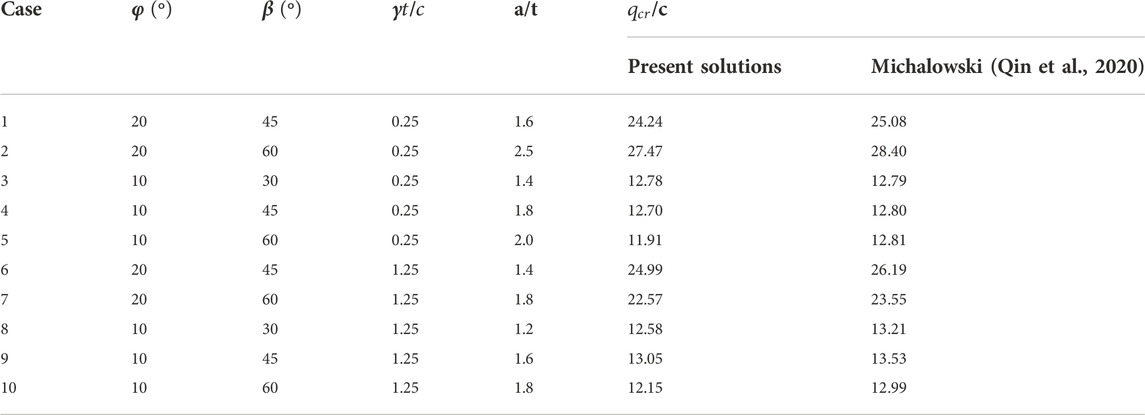
TABLE 1. Comparison between the proposed method and Michalowski (1989).
Zhou et al. (2018) evaluated the bearing capacity and failure mechanism of strip footings placed on the top of 2D slopes, using the discontinuity layout optimization (DLO) approach. The DLO approach can automatically identify the critical layout of slip-lines and the corresponding least upper bound solution of the critical load. To further validate the present approach, the limit loads computed from the proposed approach are compared with the solutions of Zhou et al. (2018) for 10 cases. In the calculations, the magnitude of H/t and
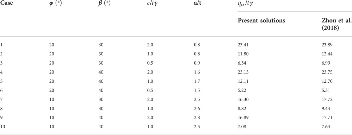
TABLE 2. Comparison between the proposed method and Zhou et al. (2018).
Parametric analysis
Several design charts are presented in Figure 5 to perform parametric analysis, each showing the limit load ratio
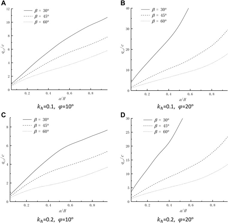
FIGURE 5. Limit load ratio
Figure 6 is presented to study the effect of the seismic force on the limit load. The limit load ratio

FIGURE 6. Limit load ratio
Figure 7 is given for investigating the effect of the shape of the local load on the magnitude of the limit load. In Figure 7, the dimensionless limit load ratio (
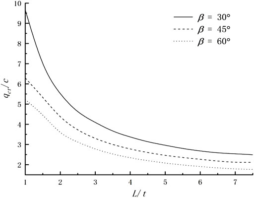
FIGURE 7. The influence of the length of the local load on the magnitude of the limit load;
Conclusion
In light of the kinematical approach of limit analysis, this paper investigates the effect of seismic force on slope bearing capacity by calculating the limit load on the top surface of slopes. In the framework of limit analysis, the stability analysis of locally loaded slopes was performed based on the translational velocity field. However, numerical research shows that the failure velocity field seems rotational. Therefore, to fill this gap, the 3D rotational failure mechanism is employed as the kinematically admissible velocity field to investigate this problem. For validation, the limit loads computed from the proposed approach are compared with the solutions available in the literature. Parametric analyses are presented to investigate the influence of different parameters on the critical loads. Based on the work above, the conclusions are drawn:
(1) Comparisons with the results of using the 3D multi-block failure mechanism and with the DLO approach show a good agreement, indicating the correctness of the proposed approach. The upper bound of limit loads computed from the proposed method is found lower than those computed using the 3D multi-blocks failure mechanism, indicating that the 3D rotational failure mechanism can improve the upper-bound estimation of the limit load from the 3D multi-block failure mechanism.
(2) The limit load is found to decrease with the increase of the seismic coefficient
(3) Parametric analysis indicates that the limit load increases with the increase of a/H or the internal friction angle
(4) The sliding surface extending to the bottom surface of the slope is not considered in this work, which is the limitation of this paper. Follow-up investigations can improve this limitation.
Data availability statement
The original contributions presented in the study are included in the article/supplementary material, further inquiries can be directed to the corresponding authors.
Author contributions
XJ: writing original draft preparation, validation, and formal analysis. QW: conceptualization and methodology, supervision.
Funding
This research was funded by the Key Programs of Zhejiang College of Security Technology, grant number: No. AF 2021Z01.
Conflict of interest
The authors declare that the research was conducted in the absence of any commercial or financial relationships that could be construed as a potential conflict of interest.
Publisher’s note
All claims expressed in this article are solely those of the authors and do not necessarily represent those of their affiliated organizations, or those of the publisher, the editors and the reviewers. Any product that may be evaluated in this article, or claim that may be made by its manufacturer, is not guaranteed or endorsed by the publisher.
References
Acevedo, A. M. G., Passini, L., Talamini, A. A., Kormann, A. C. M., and Fiori, A. P. (2021). Assessing limit equilibrium method approach and mapping critical areas for slope stability analysis in serra do mar paranaense—Brazil. Environ. Earth Sci. 80, 572. doi:10.1007/s12665-021-09863-5
Azzouz, A. S., and Baligh, M. M. (1983). Loaded areas on cohesive slopes. J. Geotech. Engrg. 109 (5), 724–729. doi:10.1061/(asce)0733-9410(1983)109:5(724)
Bai, B., Wang, Y., Rao, D., and Bai, F. (2022). The effective thermal conductivity of unsaturated porous media deduced by pore-scale SPH simulation. Front. Earth Sci. (Lausanne). 10, 943853. doi:10.3389/feart.2022.943853
Bai, B., Yang, G. C., Li, T., and Yang, G. S. (2019). A thermodynamic constitutive model with temperature effect based on particle rearrangement for geomaterials. Mech. Mater. 139, 103180. doi:10.1016/j.mechmat.2019.103180
Bai, B., Zhou, R., Cai, G., Hu, W., and Yang, G. (2021). Coupled thermo-hydro-mechanical mechanism in view of the soil particle rearrangement of granular thermodynamics. Comput. Geotechnics 137, 104272. doi:10.1016/j.compgeo.2021.104272
Baligh, M. M., and Azzouz, A. S. (1975). End effects on stability of cohesive slopes. J. Geotech. Engrg. Div. 101 (11), 1105–1117. doi:10.1061/ajgeb6.0000210
Bishop, A. W. (1955). The use of the slip circle in the stability analysis of slopes. Geotechnique 5 (1), 7–17. doi:10.1680/geot.1955.5.1.7
Gao, Y. F., Zhang, F., Lei, G. H., and Li, D. Y. (2013). An extended limit analysis of three-dimensional slope stability. Géotechnique 63 (6), 518–524. doi:10.1680/geot.12.t.004
Georgiadis, K. (2010). Undrained bearing capacity of strip footings on slopes. J. Geotech. Geoenviron. Eng. 136 (5), 677–685. doi:10.1061/(asce)gt.1943-5606.0000269
He, S., Ouyang, C., and Luo, Y. (2012). Seismic stability analysis of soil nail reinforced slope using kinematic approach of limit analysis. Environ. Earth Sci. 66, 319–326. doi:10.1007/s12665-011-1241-3
Jiang, Y., Cheng, H., and Liu, Z. (2021). Upper bound analysis of the stability of 3D slopes in the saturated soft clay subjected to seismic effect. Front. Earth Sci. 9, 795854. doi:10.3389/feart.2021.795854
Khezri, N., Mohamad, H., and Fatahi, B. (2016). Stability assessment of tunnel face in a layered soil using upper bound theorem of limit analysis. Geomech. Eng. 11 (4), 471–492. doi:10.12989/gae.2016.11.4.471
Leshchinsky, B. (2015). Bearing capacity of footings placed adjacent to c′-ϕ′ slopesslopes. J. Geotech. Geoenviron. Eng. 141 (6), 04015022. doi:10.1061/(asce)gt.1943-5606.0001306
Li, S., Huang, M., and Yu, J. (2019). Continuous field based upper-bound analysis for the undrained bearing capacity of strip footings resting near clay slopes with linearly increased strength. Comput. Geotechnics 105, 168–182. doi:10.1016/j.compgeo.2018.10.002
Meyerhof, G. (June 1957). The ultimate bearing capacity of foundations on slopes, Proceedings of the 4th international conference on soil mechanics and Foundation Engineering. London, England .
Michalowski, R. (1989). Three-dimensional analysis of locally loaded slopes. Géotechnique 39 (1), 27–38. doi:10.1680/geot.1989.39.1.27
Michalowski, R. L., and Drescher, A. (2009). Three-dimensional stability of slopes and excavations. Géotechnique 59 (10), 839–850. doi:10.1680/geot.8.p.136
Morgenstern, N. R., and Price, V. E. (1965). The analysis of the stability of general slip surfaces. Géotechnique 15 (1), 79–93. doi:10.1680/geot.1965.15.1.79
Pan, Q., Xu, J., and Dias, D. (2017). Three-dimensional stability of a slope subjected to seepage forces. Int. J. Geomech. 17 (8), 04017035. doi:10.1061/(asce)gm.1943-5622.0000913
Qin, C., Chian, S. C., and Du, S. (2020). Revisiting seismic slope stability: Intermediate or below-the-toe failure. Géotechnique 70 (1), 71–79. doi:10.1680/jgeot.18.t.001
Saran, S., Sud, V., and Handa, S. (1989). Bearing capacity of footings adjacent to slopes. J. Geotech. Engrg. 115 (4), 553–573. doi:10.1061/(asce)0733-9410(1989)115:4(553)
Sloan, S. W. (1989). Upper bound limit analysis using finite elements and linear programming. Int. J. Numer. Anal. Methods Geomech. 13 (3), 263–282. doi:10.1002/nag.1610130304
Song, D., Liu, X., Huang, J., and Zhang, J. (2021). Energy-based analysis of seismic failure mechanism of a rock slope with discontinuities using Hilbert-Huang Transform and Marginal Spectrum in the time-frequency domain. Landslides 18, 105–123. doi:10.1007/s10346-020-01491-7
Song, D., Liu, X., Huang, J., Zhang, Y., Zhang, J., and Nkwenti, B. (2021). Seismic cumulative failure effects on a reservoir bank slope with a complex geological structure considering plastic deformation characteristics using shaking table tests. Eng. Geol. 286 (3), 106085. doi:10.1016/j.enggeo.2021.106085
Song, D., Liu, X., Li, B., Zhang, J., and Vocan, J. (2021). Assessing the influence of a rapid water drawdown on the seismic response characteristics of a reservoir rock slope using time-frequency analysis. Acta Geotech. 16, 1281–1302. doi:10.1007/s11440-020-01094-5
Song, D., Liu, X., Huang, J., Wang, E., and Zhang, J. (2021). Characteristics of wave propagation through rock mass slopes with weak structural planes and their impacts on the seismic response characteristics of slopes: A case study in the middle reaches of jinsha river. Bull. Eng. Geol. Environ. 80, 1317–1334. doi:10.1007/s10064-020-02008-1
Spencer, E. (1967). A method of analysis of the stability of embankments assuming parallel inter-slice forces. Géotechnique 17 (1), 11–26. doi:10.1680/geot.1967.17.1.11
Xiao, Y., Zhao, M., Zhao, H., and Zhang, R. (2020). Numerical study on bearing capacity of ring foundations for storage tanks on a rock mass. Arab. J. Geosci. 13 (23), 1249–9. doi:10.1007/s12517-020-06255-0
Yang, X. L., and Pan, Q. J. (2015). Three dimensional seismic and static stability of rock slopes. Geomech. Eng. 8 (1), 97–111. doi:10.12989/gae.2015.8.1.097
Zhang, H., Wu, Y., Huang, S., Zheng, L., and Miao, Y. (2022). Analysis of flexural toppling failure of anti-dip rock slopes due to earthquakes. Front. Earth Sci. 9, 831023. doi:10.3389/feart.2021.831023
Appendix A
Keywords: three-dimensional slope stability, seismic force, limit analysis, local loads, 3D rotational velocity field
Citation: Ji X and Wu Q (2023) Three-dimensional seismic stability of locally loaded slopes under a rotational velocity field. Front. Earth Sci. 10:1039398. doi: 10.3389/feart.2022.1039398
Received: 08 September 2022; Accepted: 31 October 2022;
Published: 17 January 2023.
Edited by:
Huaming An, Kunming University of Science and Technology, ChinaReviewed by:
Bing Bai, Beijing Jiaotong University, ChinaKaizong Xia, Institute of Rock and Soil Mechanics (CAS), China
Danqing Song, Tsinghua University, China
Copyright © 2023 Ji and Wu. This is an open-access article distributed under the terms of the Creative Commons Attribution License (CC BY). The use, distribution or reproduction in other forums is permitted, provided the original author(s) and the copyright owner(s) are credited and that the original publication in this journal is cited, in accordance with accepted academic practice. No use, distribution or reproduction is permitted which does not comply with these terms.
*Correspondence: Qingling Wu, d3pwd3VxbEAxMjYuY29t