 Guohua Zhang
 Jiaxing Zhang
 Xiangjun Pei
 Zhihao He
 Guoxun Zheng
- 1State Key Laboratory of Geohazard Prevention and Geoenvironment Protection, Chengdu University of Technology, Chengdu, China
- 2School of Emergency Management, Xihua University, Chengdu, China
- 3Changchun Institute of Technology, Changchun, China
In this study, finite element and finite difference methods were used for numerical calculations. The law of slurry diffusion in the inclined plane cracks is summarized in this study. Further, the equation describing the diffusion of slurry with time-varying viscosity in the plane fracture with dip angle was derived, and the mathematical model of slurry diffusion control equation and improved entropy clustering algorithm were developed. Thus, the law of slurry diffusion with time-varying viscosity in an inclined plane fractured rock mass was studied in detail, and the control equation obtained was modified to improve the prediction accuracy of diffusion of slurry with time-varying viscosity. By applying the model to actual working conditions, the results highlighted that the improved entropy clustering algorithm could more accurately describe the relationship between the factors influencing slurry diffusion and the slurry diffusion radius. The improved entropy clustering algorithm model can adjust the weights of the factors influencing the slurry diffusion in the diffusion control equation, which leads to a more flexible and more accurate slurry diffusion control equation.
Introduction
Surface disaster (landslide, groundwater degradation and etc.) would be induced by human activities (Meng et al., 2020; Zhang et al., 2021a; Zhang et al., 2021b; Domínguez-Cuesta et al., 2021; Medina et al., 2021). For example, a large number of landslides in the Three Gorges Reservoir area in China, have been reactivated by reservoir impoundment since 2003 (Guo et al., 2020). To avoid different surface disasters, tunnel engineering has been widely used around world. Grouting technology is widely used in various tunnel engineering projects, especially in construction involving rock and soil materials. The use of grouting technology can effectively alter the mechanical structure of rock and soil, thus, making them more stable to meet the requirements of construction. However, the differences in the environmental factors affecting the construction projects lead to greater challenges during the operation of the grouting construction project, such as the change in the diffusion pattern of cement slurry, the incomplete slurry grouting, and the problem of slurry leakage along the joint. This can have a serious impact on the expected outcome of the grouting construction technology and interfere with the stability of the rock and soil. Therefore, several researchers in India as well as globally are no longer studying the grouting diffusion mechanism.
Sand and water inrush lead to some common geological disasters in underground systems with rich aquifers, which seriously threaten the safety of construction personnel and construction projects (Mu et al., 2020). Grouting has been proven to be an effective means of controlling the leakage of the water-rich soft stratum (Zhang et al., 2016; Li et al., 2020; Niu et al., 2020). The mechanical properties and impermeability of the stratum to be injected can be effectively improved by grouting to ensure that the stability of surrounding rock and water inflow during the excavation of the underground engineering projects meet the design requirements. Grouting reinforcement is realized by the effective diffusion of slurry (Zhang et al., 2017). The grouting reinforcement is effective if the slurry can diffuse to the boundary and then solidify. However, grouting in geotechnical engineering has the characteristics of concealment and stratum complexity, and its rule of slurry diffusion is still unclear.
In the past, the grouting seepage theory has paid too much attention to the grout flow and process. It is assumed that the injected medium is rigid, and the grout does not produce elastic deformation or plastic deformation during the seepage in the internal pores of the injected medium. Moreover, it does not consider the coupling effect between the stress field and the seepage field in the grouting process and does not exhibit the characteristics of grouting diffusion. In recent years, the studies on grouting diffusion theory considering the effects of fluid-solid coupling have gradually increased, but they have certain limitations. Researchers analyzed the coupling effect of stress and seepage fields in the grouting process (Guo et al., 2016; Hu et al., 2020). The coupled model analyzed the time-varying viscosity of the slurry during the grouting process and its influence on the diffusion radius of the slurry. Other researchers established a mathematical model considering the dynamic changes in the physical parameters such as porosity, permeability, and pore compression coefficient (Wu et al., 2018; Bauer et al., 2020). This model forms a basis for better understanding the numerical simulation of fluid-solid coupled grouting in heterogeneous strata. However, the ideal conditions have been assumed in the above research studies; therefore, the applications of the study results are limited (Śliwiński and Zachariasz 2004). The common fact about these models is that they can accurately describe the law of slurry diffusion under certain conditions. However, the model is not flexible enough and cannot be applied under complex working conditions. At present, the grouting diffusion model does not consider the permeability parameters, slurry performance index, and construction process parameters of the injected coal and rock mass to describe the law of slurry movement and diffusion range. The grouting diffusion theory is too simplified to be effectively followed for the construction process and can only be used as a reference.
In order to solve the problem of poor suitability of the existing grouting diffusion model, this paper optimizes the grouting diffusion model with the improved entropy clustering algorithm (Li et al., 2020), comprehensively considers the time variation of slurry viscosity, crack angle, grouting pressure, time and water pressure parameters, and obtains a flexible slurry diffusion governing equation. Finally, the model is verified by the engineering case of water gushing grouting plugging project in Caojiatan Coal Mine.
Diffusion mechanism of grouts based on the improved entropy clustering algorithm
Model design
The diffusion model for the grout with time-varying viscosity in fractured rocks was developed based on the following assumptions and preconditions:
(1) The slurry is an incompressible homogeneous isotropic fluid, so the slurry is isotropic, that is, the constitutive equation of the slurry in all directions is the same.
(2) The grouting is a continuous process; therefore, the continuity equation is applicable.
(3) The grout flows slowly within the fracture zone, implying laminar flow throughout the domain except for points close to the grouting hole.
(4) The flow pattern of the grout remains unchanged in the grouting process. Therefore, the grout can be rationally modeled as a kind of Bingham plastic fluid.
(5) The viscosity of the grout varies with time, which can be expressed as an exponential function. Further, there is no change in the yield value of the Bingham fluid during the grouting process.
(6) No-slip condition is observed on the wall surface during the grout flow in the fracture, implying that the flow rate of the slurry up and down the wall is approximately equal to zero.
(7) The fracture wall is impermeable to water. Therefore, the particles are not absorbed in the grout leading to no variation in the opening of the fracture.
The assumptions (1–3) are the basic assumptions for grout flow, indicating that both the continuity and Navier-Stokes (N-S) equations are applicable. The assumptions (4, 5) are obtained from the changes in the viscosity of the grout with time. The assumptions (6, 7) are also applicable to most strata.
Diffusion equation for time-varying viscosity of grouts in the planar fractures
The grouting of plane fracture rock mass with dip angle can be idealized as the continuous injection process and diffusion flow of grout through boreholes in parallel planes with constant opening, as shown in Figure 1.
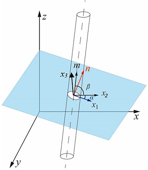
FIGURE 1. Schematic diagram of grout diffusion in a plane fractured rock mass.
Figure 1 is a simplified model of the intersection of the plane formed by the fracture centerline with the borehole. Under normal conditions, the borehole and the fracture intersect at a small vertical angle or a large angle. The central line of the fracture and the borehole form a simplified model, where the opening of the fracture is d, and the borehole radius is R0. A rectangular coordinate system x1-x2-x3 was established by considering the intersection point of the drill hole axis, and the middle line of the fracture as a coordinate origin O, wherein the direction of the axis x3 is opposite to that of gravity, and the axes x1 and x2 are horizontal with the direction determined by a right-hand rule. The outer normal directions of the borehole axis and the fracture plane are represented by the unit vectors m and n, which intersect the x1 axis by α and β, respectively, where α is the dip angle of the fracture (0°≤ α ≤ 90°) and β is the dip angle of the borehole (0°≤ β ≤ 90°). In addition, a rectangular coordinate line x-y-z was established at the origin O of the coordinate system. The z-axis is consistent with the direction of the normal line n outside the fracture plane, the x-axis is consistent with the direction of the fracture tendency, and the y-axis is determined by the right-hand rule. The angle between the major axis of the ellipse where the borehole intersects with the fracture and the x-axis is denoted by θ. When m × n = 1, θ = 0, which means that the borehole is perpendicular to the fracture surface. In this study, the case when m × n = 0 is not considered, i.e., the special case where the borehole is parallel to the fracture is not considered.
The grout begins to flow under the action of grouting pressure. With an increase in the diffusion time, the shear force of the grout is in balance with other forces such as pressure and gravity, and the flow stops. According to the N-S equation:
where u is the fluid flow velocity, p is the pressure, ρ is the fluid density, and µ is the dynamic viscosity of the fluid. Eq. 1 can be divided into four parts, with the first part being the inertial force factor, the second part being the pressure, the third part being the viscous force, and the fourth part being the other forces of the slurry. From Eq. 1, it can be observed that when the inertial force of the grout is balanced with the grouting pressure, viscous force, and external force, the grout stops spreading.
The stoppage of the grout flow indicates that the components of stress at any point in the grout are balanced, as given by Eqs. 2, 3:
In the Eqs. 2, 3, fx and fz, represent the horizontal gravity components of the slurry on the x-axis and y-axis; namely,
Since the fracture width is fixed, the gravity component of grout on the z-axis is not considered, i.e., the acting force in the y direction is considered to be balanced. ρ is the density of grout (g/cm3), and g is the acceleration of gravity. Therefore, when the flow along the y-axis is balanced, the grout flows along the x and z axes in the plane are given by Eqs. 5, 6.
In Eqs. 5, 6, the flow velocities of the grout in the x direction is vx, and the z direction is vz. p is the grouting pressure.
When the gravity in the z direction is zero, the slurry flows horizontally, and the equation is simplified as,
When the grout stops flowing, the shear stress is 0, i.e.,
Based on the improved entropy-clustering algorithm (Mu et al., 2019), the initial shear force required to drive the flow of the slurry, namely, the yield shear force, is mainly considered in the constitutive equation of the slurry given by Eq. 11.
Where τ represents the shear stress, τ0 denotes the yield shear stress, µ is the viscosity, and γ represents the rate of shear. Since the viscosity of the grout is time-dependent and follows the exponential function given by
where the values of the coefficients A and k depend on the composition of the grout with time-varying viscosity. The constitutive relation in Eq. 12 is employed in the subsequent theoretical calculations.
As a flow core exists for the fluid flows in pipes or fractures, the influence of the flow core is also taken into account in the proposed diffusion model. Therefore, the flow core regime is assumed to be identical at different sections, and the height of the flow core ae is expressed as,
where R represents the maximum diffusion size, rc denotes the radius of the grouting hole, Pc is the effective grouting pressure, Pw denotes the hydrostatic pressure of the fracture, and τ0 is the yield shear stress.
The influence of gravity should be properly considered for the inclined fractures. The slurry density is denoted by ρ. The rectangular coordinate system for horizontal fractures can be rotated by a fracture inclination angle of α, and a new coordinate system is obtained, for which the azimuth angle is represented by θ. The schematic flow model of the grout in the fracture is shown in Figure 2.
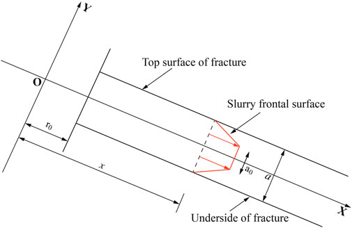
FIGURE 2. Unidirectional flow of the grout in an inclined fracture.
The major equations are established based on the fundamental equations of motion of viscous fluids, i.e., Eq. 14 and the continuity equation of incompressible fluid flow (Qing-biao et al., 2018).
For an incompressible fluid, its velocity is independent of x during the laminar flow, i.e.,
As the Bingham fluids have flow cores, the flow section is divided into three parts for calculating flow velocity, namely, upper, central, and lower zones. Then, the average velocity‾v can be evaluated as follows:
1. Under the boundary conditions
Subsequently, by imposing the boundary condition v (a/2) = 0, a solution to Eq. 17 can be obtained as follows:
where Eq. 18 highlights the velocity distribution in the upper area.
2. Flow velocity profile below the fluid core on the cross-section
Following the procedure as given in the previous step, the flow velocity at
3. Flow velocity profile of the fluid core on the cross-section
The flow velocity within the fluid core is uniform. According to the fluid velocity equations for the upper and lower areas, the fluid velocity equation at any point from the fluid core is calculated as,
4. The average flow velocity of the grout on the cross-section is computed as follows:
The average velocity is obtained by evaluating the integrals provided in Eq. 11 and some simplifications and is expressed as Eq. 22.
5. The flow volume q of the moving grout in a two-dimensional fracture is calculated by,
Eq. 24 is obtained by transforming Eq. 23 from the Cartesian coordinate system to the polar coordinate system by imposing the boundary condition p (x = r0) = p0.
Eq. 24 represents the relationship between the pressure drop Δp and the diffusion radius r, flow volume q, and the fracture opening a.
Analysis of the slurry diffusion mechanism
During the process of grouting, pressure can be formed in the porous media, which leads to the seepage of the slurry. Under external pressure, the balance of the original stress field of the injected medium is lost, and the stress is redistributed. At the same time, the injected medium framework shows the percolation effect, which leads to a change in the porosity of the medium. Therefore, there are changes in the permeability coefficient of the injected medium and the permeability field of the porous medium. The percolation effect has a significant influence on the slurry diffusion.
When the slurry diffuses in the injected medium, the solid particles in the slurry are filtered out and attached to the skeleton due to the blocking effect of the injected medium, thereby leading to a reduction in the density of the slurry, increase in the density of the injected medium, and reduction in the porosity, which is known as the permeability effect (Feng et al., 2019; Niu et al., 2020). The seepage effect usually exists in the sandy soil, normally consolidated cohesive sandy gravel soil, and other porous media, which plays a very important role in the slurry diffusion.
According to the previous studies (Zhang et al., 2016; Cui et al., 2020), the relationship between the velocity of slurry entering the void and the porosity considering the percolation effect is expressed as,
In Eq. 25 φ is the porosity of the injected medium and u the flow velocity of the slurry. u0 is the initial velocity of slurry injection, r0 is the size of the grouting hole, and r is the diffusion radius of the slurry front.
According to the slurry constitutive equation, the diffusion of slurry considering the percolation effect is expressed as follows.
In Eq. 26, λ is the percolation coefficient and δ is the cement particle content of slurry in the void.
According to the initial stress and displacement boundary conditions, the temporal and spatial variations in the cement particle are obtained by Eq. 27.
The space-time variation in the porosity of the injected medium is given by,
In Eq. 28, ω is the initial cement particle content of the slurry and φ0 is the initial porosity of the injected medium. According to Darcy’s law (Wang et al., 2020), the radial grouting pressure distribution model is given by,
In Eq. 29, k0 is the initial permeability coefficient of the injected medium and β is the function parameter.
Engineering test
Overview
The Caojiatan minefield is located in the west-central of the Yushin phase I mining area. The total area of the minefield is 109.28 km2. The first stage of the minefield is about 12.55 km long, 3.03 km wide, and covers an area of about 37.28 km2. The inclined shafts are employed for future development, and the bottom elevation of the main and auxiliary shafts is about +958.8 m.
The main inclined shaft is dipped at an angle of 12° and obliquely extended for 1,674 m. Its corresponding tunnel is 5.8 m wide and 4.1 m high, and the sidewall is 1.2 m high. The rubble stone thick layers of 0.5 m and thick C40 concrete of 0.2 m lie at the bottom of the tunnel.
The auxiliary inclined shaft is dipped at an angle of 5.5° and obliquely extended for 3970 m. Further, its pertinent tunnel is 6.0 m wide and 4.8 m high, and the sidewall is 1.8 m high. The rubble stone thick layers of 0.5 m and thick C40 concrete of 0.3 m lie at the bottom of the tunnel.
The water flows into the shafts at the rate of 160 m³/h when the main and auxiliary inclined shafts were drilled into the red soil layer and bedrock sections. Figure 3 shows the water leakage characteristics of the borehole in the 510 m–670 m section of the roadway.
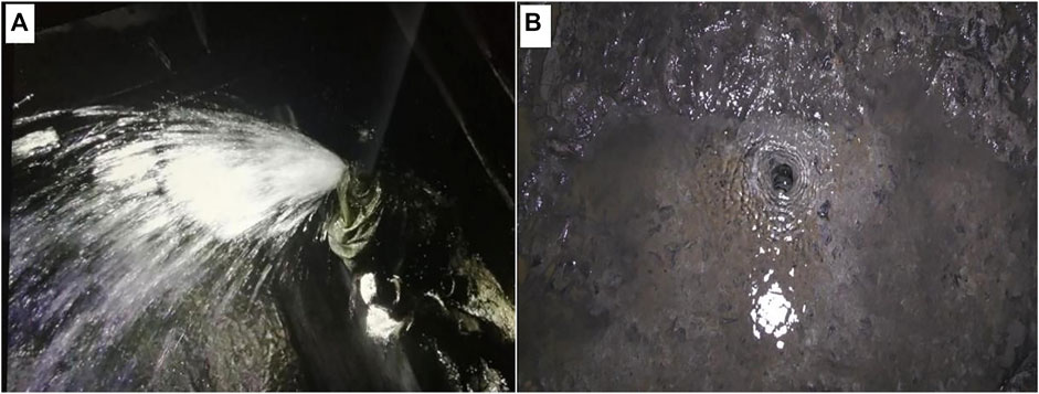
FIGURE 3. Groundwater leakage before and after grouting, (A) Water flowing out of a single hole placed at 510 m–670 m segment, with a rate of up to 60 m3/h before grouting, (B) Characteristics of leakage after grouting.
Technical plan for the engineering test
The segment at 1,200–1,235 m of the auxiliary inclined shaft was chosen for the grouting tests. The mid-deep (5–16 m) displacement grouting and plugging technology were adopted for the study. Initially, a hole was drilled to discharge water and reduce pressure, followed by the blockage and drainage of water in a concentrated manner. After backfill grouting at the cavity of the borehole wall (especially the bottom plate), the deep sand layer was washed and replaced by the grout to form a deep impermeable zone. Finally, the shallow layers were properly grouted.
Two pilot holes were drilled for the main and auxiliary inclined shafts for sampling before drilling grouting holes on the ground to locate aquifers in the sand layers and weathered bedrocks in the target section. Later, water pressure tests were conducted in the pilot holes of the weathered bedrocks to determine their permeability characteristics. The water injection tests were conducted following the Code of Water Pressure Test in Borehole for Hydropower and Water Resources Engineering (DL/T5331–2005) as shown in Figure 4.
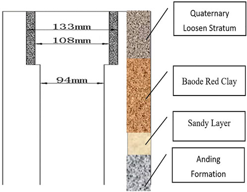
FIGURE 4. Diagram of the borehole structure of the pilot holes.
The water pressure test was accompanied by fracture cleaning. The test pressure was about 80% of the grouting pressure but not higher than 1 MPa. The water pressure test was carried out for 30 min (excluding the fracture cleaning time), and the water flow was measured and recorded every 5 min. The water flow at the maximum pressure was used for calculating Eq. 30.
where q is the permeability (Lu), Q denotes the water flow flux (L/min), L is the length of the test section (m), and P is the ground pressure (MPa).
The curtain grouting holes were arranged in three rows on each side, and the holes were 1.5 m away from each other in each row and line. The holes were about 145 m deep. Five rows of interconnected grouting holes were arranged at depths of 510 m and 670 m in the main shaft, and at depths of 1,200 m and 1,450 m in the auxiliary shaft. The rows were spaced 1.5 m apart, and the holes in each row were spaced 0.8–1.0 m apart. There were nine holes in each row at a depth of 20–25 m, with an average depth of 22.5 m.
The drilling load consisted of a total of 711 curtain grouting holes and 45 underground grouting holes arranged for the main shaft. Further, 1,071 curtain grouting holes and 45 underground grouting holes were organized for the auxiliary shaft as shown in Figure 5.
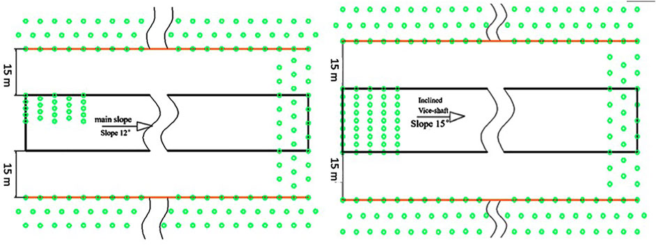
FIGURE 5. Plan layouts of the curtain grouting holes of the main and auxiliary shafts.
Based on the stratification and in situ situation, the ground grouting holes were drilled to a depth of 145.0 m, and the diameter of the surface hole was 133 mm. When the shaft reached the loose soil layer, a Φ108 mm surface casing for wall protection runs in, and a Φ94 mm drilling bit was used to drill to the final horizon. The interconnected grouting holes in the tunnels were 20.0–25.0 m deep, and the diameters of the holes ranged from 42 to 94 mm.
According to the Eqs. 28, 29, after thoroughly considering the geological conditions, the grouting process is designed as Figure 6.
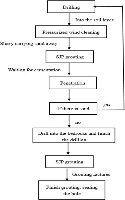
FIGURE 6. Flowchart of the grouting process.
The grouting pressure is the pressure obtained during the grouting tests that can ensure the expected grouting effects for a typical stratum. The overall pressure is calculated by,
where PZ represents the overall grouting pressure (MPa), PQ denotes the pressure at the grouting hole (MPa), H is the length of the grouting section (m), rgrout is the grout density (g/cm3), and Pw is the water inflow pressure (MPa).
Analysis of the results
The water inflow in the test section reduced from 44 m³/h to 4 m³/h, i.e., by 40 m³/h, and the reduction was 91%, which was within the expected value of 90%. The overall water yield for the section above 1,420 m declined by 30 m³/h.
The water yield was measured at regular intervals, and the measured data on 30 Dec 2020, was as follows, Y1:1,170 m, 33 m³/h; Y2:1,200 m, 33 m³/h; Y3:1,235 m, 37 m³/h; and Y4:1,420 m, 128 m³/h. The water yield for the 1,200–1,235 m section was reduced by 40 m³/h, i.e., up to 91%, and the overall water yield for the section above 1,420 m was reduced by 30 m³/h, i.e., up to 19%, as shown in Figure 7.
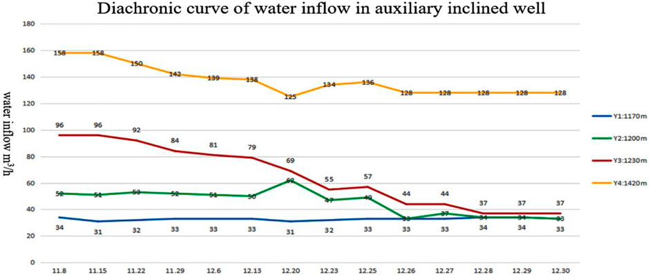
FIGURE 7. Trends of reduction in the water yield after groutin.
Conclusion
Based on the time-varying viscosity model of the fluid and the fluid balance equation showing the time-varying viscosity of the slurry, a single inclined plane fracture grouting diffusion model was established in this study. The final grouting diffusion characteristics can be predicted using the finite difference method under the conditions of known grouting pressure, initial yield stress, and fracture parameters. The model is suitable for grouting prediction of fractured rock mass and layered channel, which can be used for grouting reinforcement of fractured rock mass and sealing engineering of water inrush in tunnel.
The final grouting diffusion characteristics can be predicted at the single inclined plane fracture when the grouting rate is constant. This study developed the model highlighting variational characteristics of slurry velocity under plane fracture, the model highlighting the changes in slurry pressure with diffusion radius under constant grouting rate, and the model highlighting the changes in slurry diffusion radius with the time-varying viscosity of the slurry, which can help in the prediction of the changes in the slurry diffusion radius with time under fixed grouting rate and grouting pressure. The results of the physical tests and the engineering verification studies indicate that the proposed methodology can effectively estimate the grouting characteristics of the plane fractures. In the engineering project verification, based on the working conditions at the Caojiatan coal mine, the improved entropy fusion algorithm was used to calculate the example considered in this study, and the curtain grouting method was used to block the underground water inflow, which led to a good plugging effect. The engineering practice has proved that the estimation of slurry diffusion by the improved entropy fusion algorithm can more accurately describe the relationship between the grouting time and the diffusion radius of the slurry with time-varying viscosity and can theoretically guide the relevant grouting projects. According to this result, the team will pay more attention to the study of grouting diffusion mechanism of viscosity time-varying slurry in the case of large dip angle fracture and complex fracture in the future research.
Data availability statement
The datasets presented in this study can be found in online repositories. The names of the repository/repositories and accession number(s) can be found in the article/Supplementary Material.
Author contributions
All authors listed have made a substantial, direct, and intellectual contribution to the work and approved it for publication.
Acknowledgments
The authors are grateful for the financial support of the Key Research and Development Programme of Sichuan Province (2021YFQ0066); State Key Laboratory of Geohazard Prevention and Geoenvironment Protection (China) Open Fund (SKLGP 2022K021).
Conflict of interest
The authors declare that the research was conducted in the absence of any commercial or financial relationships that could be construed as a potential conflict of interest.
Publisher’s note
All claims expressed in this article are solely those of the authors and do not necessarily represent those of their affiliated organizations, or those of the publisher, the editors and the reviewers. Any product that may be evaluated in this article, or claim that may be made by its manufacturer, is not guaranteed or endorsed by the publisher.
References
Bauer, J. T., Montero, X., and Galetz, M. C. (2020). Fast heat treatment methods for al slurry diffusion coatings on alloy 800 prepared in air. Surf. Coatings Technol. 381, 125140. doi:10.1016/j.surfcoat.2019.125140
Cui, W., Tang, Q. -W., and Song, H. -F. (2020). Washout resistance evaluation of fast-setting cement-based grouts considering time-varying viscosity using CFD simulation. Constr. Build. Mater. 242, 117959. doi:10.1016/j.conbuildmat.2019.117959
Domínguez-Cuesta, M. J., Quintana, L., Valenzuela, P., Cuervas-Mons, J., Juan, L. A., and Silverio, G. C. (2021). Evolution of a human-induced mass movement under the influence of rainfall and soil moisture. Landslides 18 (11), 3685–3693. doi:10.1007/s10346-021-01731-4
Feng, X., Zhang, Q., Jiang, Q., Song, S., Kong, X., Liu, R., et al. (2019). Study on variation law of cement slurry density in porous media considering convection–diffusion–infiltration. Arab. J. Geosci. 12 (23), 1–11. doi:10.1007/s12517-019-4826-x
Guo, Y., Wang, Y. -Q., Wang, Z.-M., and Shen, C. -J.(2016). Study on the preparation and characterization of high-dispersibility nanosilica. Sci. Eng. Compos. Mater. 23 (4), 401–406. doi:10.1515/secm-2014-0010
Guo, Z., Chen, L., Yin, K., Shrestha, D. P., and Zhang, L. (2020). Quantitative risk assessment of slow-moving landslides from the viewpoint of decision-making: A case study of the three Gorges reservoir in China. Eng. Geol. 273, 105667. doi:10.1016/j.enggeo.2020.105667
Hu, Y., Liu, W., Shen, Z., Gao, K., Liang, D., and Cheng, S. (2020). Diffusion mechanism and sensitivity analysis of slurry while grouting in fractured aquifer with horizontal injection hole. Carbonates Evaporites 35 (2), 49–16. doi:10.1007/s13146-020-00587-4
Li, S., Pan, D., Xu, Z., Lin, P., and Zhang, Y. (2020). Numerical simulation of dynamic water grouting using quick-setting slurry in rock fracture: The sequential diffusion and solidification (SDS) method. Comput. Geotechnics 122, 103497. doi:10.1016/j.compgeo.2020.103497
Medina, V., Hürlimann, M., Guo, Z., Lloret, A., and Vaunat, J. (2021). Fast physically-based model for rainfall-induced landslide susceptibility assessment at regional scale. Catena 201, 105213. doi:10.1016/j.catena.2021.105213
Meng, Z., Liyi, C., Shanyong, W., and Honggang, W. (2020). Experimental study of the microstructure of loess on its macroscopic geotechnical properties of the Baozhong railway subgrade in Ningxia, China. Bull. Eng. Geol. Environ. 79 (9), 4829–4840. doi:10.1007/s10064-020-01816-9
Mu, W., Li, L., Yang, T., Yao, L., and Wang, S. (2020). Numerical calculation and multi-factor analysis of slurry diffusion in an inclined geological fracture. Hydrogeol. J. 28 (3), 1107–1124. doi:10.1007/s10040-019-02103-y
Mu, W., Li, L., Yang, T., Yu, G., and Han, Y. (2019). Numerical investigation on a grouting mechanism with slurry-rock coupling and shear displacement in a single rough fracture. Bull. Eng. Geol. Environ. 78 (8), 6159–6177. doi:10.1007/s10064-019-01535-w
Niu, J., Wang, B., Feng, C., and Chen, K. (2020). Experimental research on viscosity characteristics of grouting slurry in a high ground temperature environment. Materials 13 (14), 3221. doi:10.3390/ma13143221
Śliwiński, J., and Zachariasz, T. (2004). Effect of particle size distribution and content of superabsorbent polymer (SAP) on the basic properties and porosity of cement paste. Cem. WAPNO BETON. 2017 (4):289-298
Wang, Y., Ao, W., Ortega-Fernández, I., Liang, D., Li, H., Jiang, B., et al. (2020). Research of time-varying performance of solar distributed thermal-power plant with neutral network prediction. Energy Convers. Manag. 224, 113333. doi:10.1016/j.enconman.2020.113333
Wang, Q.-b., Zhu, Q.-k., Shao, T.-s., Yu, X.-g., Xu, S.-y., Zhang, J.-j, et al. (2018). The rheological test and application research of glass fiber cement slurry based on plugging mechanism of dynamic water grouting. Constr. Build. Mater. 189, 119–130. doi:10.1016/j.conbuildmat.2018.08.081
Wu, J., Feng, M., Chen, Z., Mao, X., Han, G., and Wang, Y. (2018). Particle size distribution effects on the strength characteristic of cemented paste backfill. Minerals 8 (8), 322. doi:10.3390/min8080322
Zhang, J., Zhao, H., Wang, C., Li, W., Xu, J., and Liu, H. (2016). The influence of pre-absorbing water in coal on the viscosity of coal water slurry. Fuel 177, 19–27. doi:10.1016/j.fuel.2016.02.088
Zhang, Q. -S., Zhang, L. -Z., Liu, R. -T., Li, S. -C., and Zhang, Q. -Q. (2017). Grouting mechanism of quick setting slurry in rock fissure with consideration of viscosity variation with space. Tunn. Undergr. Space Technol. 70, 262–273. doi:10.1016/j.tust.2017.08.016
Zhang, Y., Dai, Y., Wang, Y., Huang, X., Xiao, Y., and Pei, Q. (2021a). Hydrochemistry, quality and potential health risk appraisal of nitrate enriched groundwater in the Nanchong area, southwestern China. Sci. Total Environ. 784, 147186. doi:10.1016/j.scitotenv.2021.147186
Keywords: time-varying viscosity, diffusion control equation, numerical simulation, improved entropy clustering algorithm, finite element method
Citation: Zhang G, Zhang J, Pei X, He Z and Zheng G (2023) Study on numerical simulation method of viscosity time-varying slurry diffusion law. Front. Earth Sci. 10:1038792. doi: 10.3389/feart.2022.1038792
Received: 07 September 2022; Accepted: 31 October 2022;
Published: 13 January 2023.
Edited by:
Zizheng Guo, Hebei University of Technology, ChinaCopyright © 2023 Zhang, Zhang, Pei, He and Zheng. This is an open-access article distributed under the terms of the Creative Commons Attribution License (CC BY). The use, distribution or reproduction in other forums is permitted, provided the original author(s) and the copyright owner(s) are credited and that the original publication in this journal is cited, in accordance with accepted academic practice. No use, distribution or reproduction is permitted which does not comply with these terms.
*Correspondence: Jiaxing Zhang, emp4MTk5MkBvdXRsb29rLmNvbQ==