 Liu Yanqian1
 Dong Mengling
95% of researchers rate our articles as excellent or good
Learn more about the work of our research integrity team to safeguard the quality of each article we publish.
Find out more
ORIGINAL RESEARCH article
Front. Earth Sci. , 06 January 2023
Sec. Structural Geology and Tectonics
Volume 10 - 2022 | https://doi.org/10.3389/feart.2022.1037532
This article is part of the Research Topic Quantitative Characterization and Engineering Application of Pores and Fractures of Different Scales in Unconventional Reservoirs – Volume II View all 39 articles
In the drilling and completion process of fractured formations, wellbore stability is a key factor affecting the safety of drilling and completing engineering. Previous studies have demonstrated that propping moderately and plugging fractures with soluble particles can improve formation fracture pressure. When it comes to particle transport in 3D rough propagation fractures, the interactions between particle-fracture-fluid need to be considered. Meanwhile, size-exclusion, particle bridging/strain effects all influence particle transport behavior and ultimately particle plugging effectiveness. However, adequate literature review shows that fracture plugging, and fracture propagation have not been considered together. In this study, a coupled CFD-DEM method was put forward to simulate the particle plugging process of propagating fracture, and the effects of positive pressure difference, fracture roughness, particle concentration, and particle shape on the plugging mechanism were examined. It is concluded through the study that: 1) Positive pressure difference too large will lead to excessive fracture aperture, making the particles unable to form effective plugging in the middle of the fracture; positive pressure difference too small will lead to fracture aperture too small, making particles unable to enter into and plug the fracture. 2) No matter how the concentration, particle size and friction coefficient change, they mainly affect the thickness of the plugging layer, while the front end of the particle is still dominated by single-particle bridging, and double-particles bridging and multiple-particles bridging are hardly ever seen. For the wellbore strengthening approaches, such as stress cages, fracture tip sealing, etc., specific analysis should be carried out according to the occurrence of extended fractures. For example, for fractures with low roughness, the particles rarely form effective tight plugging in the middle of the fracture, so it is more suitable for fracture tip sealing; For the fracture with high roughness, if the positive pressure difference is controlled properly to ensure reasonable fracture extension, the particle plugging effect will be good, and the stress cage method is recommended for borehole strengthening.
According to statistics, about 57% of the world’s oil and gas reserves and 60% of the world’s oil and gas production come from carbonate reservoirs, and almost all high-production wells are in carbonate reservoirs (Moore and Wade, 2013; Fan et al., 2022; Li 2022). In the drilling and completion process of natural fractured formations in extensive and complex distribution, the safe density range of drilling fluid is narrow; if the drilling fluid density is too high, the naturally closed fractures may be opened to expand, bringing about loss of drilling fluid at various degrees in the drilling and completion process (Li et al., 2014; Li et al., 2018). Once happening, the drilling fluid leakage may cause not only drilling fluid loss, consumption of loss control materials, but also reservoir damage, in serious cases, even well collapse and blowout, which threatens safe and efficient drilling and makes non-productive time and operating costs increase significantly (Civan, 2015; Li J. et al., 2022). But the opening of fracture is not entirely a bad thing, as previous studies have demonstrated that propping moderately and plugging fractures with soluble particles can help stop fracture extension and improve wellbore stability (Feng and Gray, 2015; Feng et al., 2016; Li et al., 2019; Figure 1).
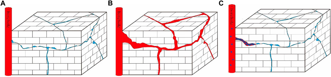
FIGURE 1. Plugging process of propagation fracture. (A) Before fracture extension; (B) Fracture extension due to positive pressure difference; (C) Re-closed fracture after plugging.
Figuring out the particle plugging mechanisms of propagation fracture is the basis of effective plugging. In terms of plugging mechanisms of fractured strata, a lot of research has been carried out mainly by means of core experiment, physical simulation experiment and numerical simulation. Some researchers have evaluated the coupling relationship between fracture width, fracture roughness, particle properties and pressure-bearing capacity of plugging layer through core and steel plate seam experiments, and obtained laws such as 1/3 bridging, ideal filling bridging, and 1/2 bridging (Kuzmina et al., 2018; Feng et al., 2020; Li H. et al., 2022). However, the vast majority of experiments have high occasionality, long experimental cycle, and high time and economic costs, and cannot explain the bridging and plugging mechanism of plugging particles visually from a microscopic perspective. Numerical simulation method can simulate restricted experiments and facilitate the analysis of microscopic mechanisms. In recent years, CFD-DEM numerical simulation methods (including LBM-DEM) have been widely used in studying solid-phase particle invasion and plugging in fractures. Boutt (2006) observed particle trapping behavior of fracture roughness by LBM-DEM method. Koyama (2008) analyzed the effects of fracture shear and fracture surface coupling on colloidal transport with particle tracking method. Zhang (2019a) investigated the wall effect and hydrodynamic behavior in coupled rough fracture with CFD-DEM method. In addition, particle bridging and size exclusion effects in regular fractures (Pu and Wang, 2014; Dai and Grace, 2016; Zeng et al., 2016; Huang et al., 2018; Jia et al., 2020; Zhu et al., 2020) and uncoupled actual fractures (Feng et al., 2018) have also been investigated extensively, and a large number of quantitative relationships between the particle bridging probability and particle concentration, particle size and fracture width have been proposed. Zhu et al. (2020) also analyzed the particle plugging behavior during the dynamic variation of fracture width under positive pressure difference with a combined CFD-DEM finite element method.
Fracture extension, which is essentially a problem of the weakening of fracture closure under different normal effective stresses, belongs to the domain of fracture stress sensitivity study. To date, a large number of experimental and numerical simulation studies have been carried out and a large number of theoretical equations have been obtained in this aspect. Lab experiments on rough rock fractures focused more on the study of the effect of normal stress on fluid flow in rock fracture, that is known as stress sensitivity test (Cao and Lei, 2018; Zhang J. et al., 2019; Yang et al., 2020). When it comes to particle transport in three-dimensional rough propagation fractures, it is necessary to consider not only the effect of fracture extension on fluid flow, but also the interaction between particle-fracture-fluid. Size exclusion, particle bridging/strain effect of particles all influence transport behavior and ultimately plugging effect of the particles (Ahfir et al., 2017; Khan et al., 2017; Wu et al., 2018; Xu et al., 2018). Although a lot of research on the static fracture plugging and stress sensitivity has been done and a large number of research results have been obtained, fracture plugging and fracture extension have not been considered together. The purpose of this study is to find out the transport and plugging mechanism of plugging particles under the action of macroscopic pressure gradient and fracture expansion. To this end, firstly, synthetic fractures with different roughnesses were generated using a self-profiling fractal model based on geological features. Then, the behavior and mechanisms of transport, plugging and permeability variation of plugging particles in propagation fractures with different roughnesses and positive pressure differences were examined by CFD-DEM method.
Plugging particles in drilling fluid will enter into the reservoir with drilling fluid under positive pressure difference, and the dynamic behavior between plugging particles, drilling fluid and fracture in this process belongs to the domain of coupling of liquid and solid phases. The CFD-DEM coupling algorithm considers the couplings between plugging particles, plugging particles and drilling fluid, plugging particles and fracture medium, and drilling fluid and fracture medium, and is able to capture the micro-mechanisms of particle transport, precipitation, capture, and plugging.
Current methods obtaining fracture morphology include contact or non-contact quantitative scanning methods, and numerical synthesis method. But due to the uncertainty of fracture formation, the cost of obtaining a large number of fractures with different geometric information is huge. Therefore, in this study, the software Synfrac designed by the University of Leeds was used to generate synthetic fractures (Ogilvie et al., 2006). Synthetic fractures not only have almost the same geometric characteristics as natural fractures, but also can have specific parameter values and be generated independently to test the effect of specific parameter variables of fracture propagation and particle flow. The mathematical model proposed by Brown (1995) was used to generate synthetic fractures. In this method, a two-dimensional complex amplitude spectrum with random phase component obeying a decaying power law was constructed, and Fourier inverse transformation was done to the amplitude spectrum to obtain a self-affine curved surface. To ensure that all samples had the same dimensions and the same vertical scale, the initial sample of 50 mm × 50 mm was corrected to a resolution of 512 × 512, which was configured with a standard deviation of 1 mm for the height of the irregular rough surface to obtain a geometrically isotropic fracture surface (Figure 2). According to previous studies, fracture samples of similar roughness generated by different random numbers have similarity in hydraulic laws, so the simulation results of one random number are given in this paper.
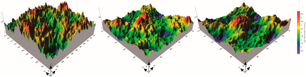
FIGURE 2. Features of generated fracture surfaces.
The fracture roughness coefficient (JRC) proposed by Barton and Choubey (1977) can be calculated using the following equation (Tse and Cruden, 1979):
Where: Z2 is the root mean square of the first order derivative of the fracture surface, which can be expressed in discrete form as:
Where
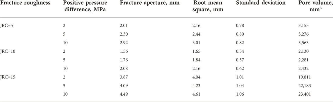
TABLE 1. Geometric characteristics of propagating fractures.
For rough fractures, the fracture deformation is governed by the following equation:
Where,
Where:
Where:
It can be obtained that
For natural rough fractures, the fracture roughness influences the degree of fracture closure, and the variation of the fracture mechanical aperture is obtained by correcting the following relationship.
An initial fracture often has a high degree of closure and a large contact area. When its two opposing surfaces just touch or penetrate each other, the contact distance is negative, representing a contact area with zero pore size. The numerical generation of the propagation fracture was simulated by assigning rising expansion increments to the upper surface of the fracture under different positive pressure differences, and after gradual lifting of the upper surface of the fracture, part of the contact was released and some new voids were created at the same time. In this study, the evolution of geometric characteristics of initial fractures with JRC of 5, 10 and 15 at the positive pressure differences of 0–10 MPa were simulated (Figure 3; Table 1).
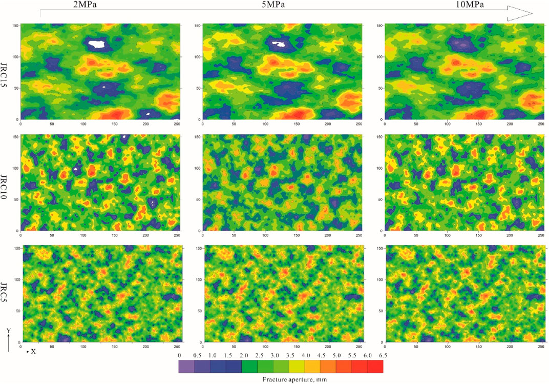
FIGURE 3. Characteristics of propagating fractures.
In the computational study, the plugging particle transport was solved by the discrete element method in the Lagrangian framework, and the plugging particles followed the second law. When the plugging particles transport in the fracture with drilling fluid, each plugging particle is subjected to the actions of surrounding drilling fluid, adjacent particles and adjacent fracture surface, so the external forces on the plugging particle during transport include its own gravity, traction, buoyancy and contact force etc. Its motion mainly includes translation and rotation, and the governing equations are as follows:
Where
Besides the interactions between particles and between particle and fracture surface, the interaction between drilling fluid and plugging particle also need to be considered. The drilling fluid flow is often solved by the finite volume method, but the coupling interaction between plugging particle and drilling fluid are often solved in two ways, particle unresolved (Unresolved) and particle-resolved (Resolved) CFD-DEM methods, their main difference is the ratio of particle diameter to fluid grid size. The choice of the specific method depends on the scale of the engineering issue: size of particles, and flow field resolution etc. The particle non-resolved CFD-DEM is suitable for large-scale calculations, which require particle diameter smaller than the CFD grid size. It uses an empirical model to calculate the force of the fluid on the particle and will calculate the reaction force of the particle on the fluid based on Newton’s third law, which is expressed as a source term in the N-S equation, while the occupation of the flow field space by the particle is reflected in the volume fraction calculation. The method uses an empirical model and a relatively coarse flow field, so it is able to calculate industrial-level particle flow issues.
In this study, the fluid had a Reynolds number of less than 200, the flow regime of drilling fluid was laminar flow, and the requirement of flow field resolution in a single fracture was not high, so the CFD-DEM method with non-resolved particles was used for the evaluation of plugging particle intrusion damage and temporary plugging in fracture-type reservoirs; while fracture-pore type reservoir has complex pore structure and flow field, and small vortices which would have serious influence on plugging particle retention, so the flow field must be resolved in detail, therefore, solid-phase intrusion damage in fracture-pore reservoirs was simulated by the particle-resolved CFD-DEM method.
In the particle unresolved CFD-DEM method, the fluid was assumed to be continuous and incompressible and can be described by the locally averaged N-S equation.
Where:
Where:
As a simplification, the DEM calculation at the coupling step time was required to ensure that the fluid forces on the particle remained constant, while the coupling was performed after about 50–100 DEM steps.
Continuous particles of the desired concentration were created in the simulated borehole to simulate steady particle inflow. Constant pressure boundary conditions were applied at the inlet (top of the borehole) and outlet (end of the fracture), and anti-slip wall conditions were applied at the fracture surface (Figure 4). In this study, the fluid was assumed to be a Newtonian fluid in laminar flow regime, and the specific fluid parameters are shown in Table 1. The plugging particles were assumed to be calcium carbonate particles most commonly used in drilling operations (Table 2). The selection of CFD grid size depends on the balance between the fracture surface details, fluid details and the computational stability of the fluid volume fraction.
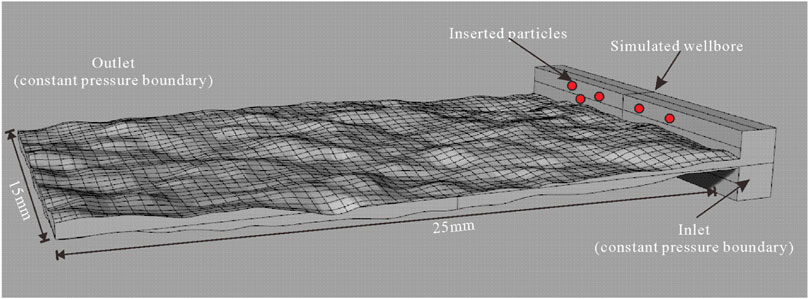
FIGURE 4. Schematic illustration and CFD mesh of the fracture.
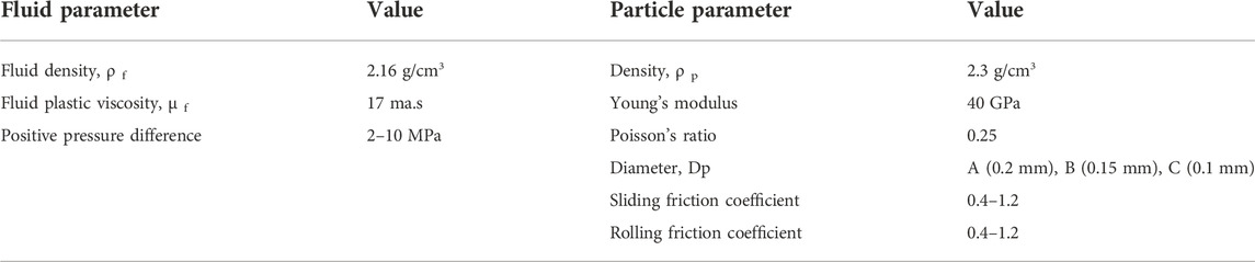
TABLE 2. Parameters used in the simulation.
With the increase of positive pressure difference, the fracture gradually opened, extended, and increased in average width, at which time it becomes difficult for the particles to bridge and plug. The white particles in all plugging results figures represent the particles in a static state (velocity less than 0.01 m/s) after plugging (Figure 5), and the white particles in the following figures have the same meaning. It can be seen from Figure 5 that when the positive pressure difference was less than 5 MPa, the particles formed a large area of stable bridging and plugging, but when the positive pressure difference was greater than 5 MPa, the particle bridging was difficult, and only slight bridging was formed in a small part of the area, and the fracture was not plugged on the whole. In terms of the shape of plugging layer, when the positive pressure difference was 2 MPa, the plugging layer was thicker, and effective plugging was formed in a large part of the fracture, and only a few grooves were left for drilling fluid and plugging particles to move; when the positive pressure difference was 5 MPa, although particle bridging plugging was also formed, the plugging layer was thinner, and the number of grooves for fluid movement after plugging increased; when the positive pressure difference was 10 MPa, the plugging layer was sporadically distributed, each plugging position had less plugging particles, most of the grooves still provided a large amount of flow space. From the perspective of fluid pressure gradient distribution, we can see that when the positive pressure difference was less than 5 MPa, a stable pressure plugging zone was formed at the front of the plugging layer, but the pressure plugging was more serious when the positive pressure difference was 2 MPa; but when the positive pressure difference was 10 MPa, the pressure gradient was basically linearly distributed, which means that the plugging completely failed at this point. In actual drilling operation, this situation will not only lead to the failure of borehole reinforcement, but also lead to man-made well leakage, and must be avoided.
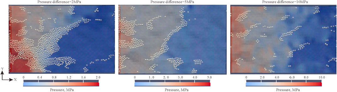
FIGURE 5. Variation of fracture plugging law under different positive pressure differences in JRC15 (at the particle concentration of 10%, friction coefficient of 0.9, particle size of 100% A).
Figure 6 shows the variations of permeability retention rate and particle discharge rate in the plugging process, where permeability retention rate is defined as the ratio of fracture permeability after particle injection
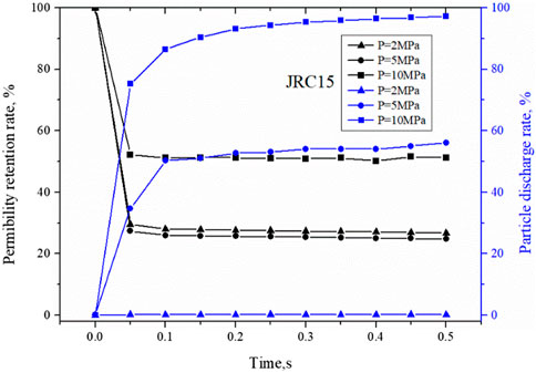
FIGURE 6. Variations of fracture permeability retention rate and particle discharge rate of JRC15 with time at different positive pressure differences.
Particle discharge efficiency is defined as the ratio of the total number of particles discharged from the end of the fracture
It can be seen from Figure 6 that when the positive pressure difference was less than 5 MPa, a stable plugging layer was formed gradually within 0.1 s, and the permeability retention rate was less than 30% at this point; when the positive pressure difference was 10 MPa, the permeability of the fracture after particle injection decreased to some extent, but finally stabilized at about 50%. From the particle discharge rate, we can see that when the positive pressure difference was 2 MPa, basically no particles were discharged and all particles were involved in bridging; when the positive pressure difference was 5 MPa, the particle discharge rate increased to 60%, which means that although effective plugging was formed at this point, there were still a large number of particles continuously invading into the deep part of the fracture, and the pressure and fluid were not completely isolated in this case, which is not conducive to well wall stability and reservoir protection; when the positive pressure difference was 10 MPa, the particle discharge rate gradually approached 100% over time, that is, all injected particles invaded to the deep part of the reservoir and no stable bridging was formed, which was a complete failure.
Figure 7 shows force chain structures of the plugging layers formed by different sizes of particles under the positive pressure difference of 10 MPa. It can be seen from the figure that when the particle size/average fracture width ratio was 1.03, the particles formed a stable plugging layer near the entrance, and the force chain strength of the plugging layer was high overall; when the particle size/average fracture width ratio was 0.92, the particles formed a plugging layer at local parts of the fracture, and the force chain strength of plugging layer was weaker; when the particle size/average fracture width ratio was 0.56, no strong force chain formed inside the whole fracture.

FIGURE 7. Force chain structure of plugging formed by different sizes of particles in JRC15.
The different roughness of the fracture surface affects the geometric structure of flow space in the fracture, which in turn affects the transport pattern of fluid and particles in it. In this study, the transport and plugging of particles in fractures with different roughnesses at different positive pressure differences were simulated, as shown in Figure 8. The particle size/initial average fracture width ratio in the figure was 0.9. It can be seen that when the positive pressure difference was 2MPa, JRC5 and JRC10 only had a plugging layer near the fracture entrance, while the particles could not make into the lower half of the fracture; and in the fracture JRC15, the particles filled the whole fracture to form tight plugging, resulting in obvious pressure seal. When the positive pressure difference was 5 MPa, both fractures JRC5 and JRC10 had plugging only in the local parts but several grooves remained for fluid flow, and the pressure and fluid isolation were poor; in contrast, in fracture JRC15, although the plugging layer was thin, a long continuous plugging zone formed in the middle of the fracture, and a tight plugging layer was likely to form with subsequent injection of fine particles. When the positive pressure difference was 10MPa, all the fractures were not effectively plugged.
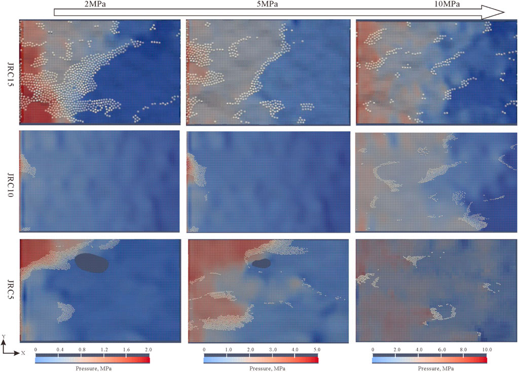
FIGURE 8. Particle plugging results of fractures with different roughnesses at different positive pressure differences (particle concentration of 10%, friction coefficient of 0.9, particle size/fracture width of 0.9).
Figure 9 shows the variations of permeability retention rate and particle discharge rate with time in fractures JRC5 and JRC10. In combination with Figure 6, it can be seen that with the increase of fracture roughness, permeability retention rate shows a trend of gradual decrease. When the positive pressure difference was 2–5 MPa, the permeability retention rates of JRC5, JRC10 and JRC 15 were 40–50%; 40–60%, and 20–30% respectively. When the positive pressure difference was 10 MPa, all the three fractures had higher permeability retained after particle injection regardless of the roughness, indicating the plugging effect was poor. In terms of the particle discharge rate, it can be found that when the positive pressure difference was 2MPa, all the three fractures had a particle discharge rate close to 0%. But combined with the graph of plugging effect, it can be seen that JRC5 and JRC10 had plugging layer at their entrances and a large amount of grooves retained for fluid flow, so the plugging layers in them were poor in stability and tightness. When the positive pressure difference was 5 MPa, the particle discharge rates in JRC5 gradually approached 100%, while that in JRC15 was stable at about 60%. In other words, the grooves in JRC5 were not plugged finally, while in JRC15, a better plugging layer formed with the injection of particles. When the positive pressure difference was 10 MPa, all the fractures had a particle discharge rate close to 100%, indicating no effective plugging was formed.
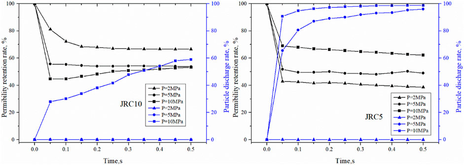
FIGURE 9. Variations of permeability retention rate and particle discharge rate of fractures with different roughnesses at different positive pressure differences.
From the above discussion, it can be seen that for the fracture with low fracture roughness, the particles injected either form a plugging layer at the entrance or plug local parts of the fracture, and are hard to form effective tight plugging in the middle of the fracture. Therefore, for this kind of fracture, strengthening well wall by the stress cage way may not be effective, and the fracture tip plugging is recommended to prevent further expansion of the fracture. Whereas for fractures with high roughness, as long as the positive pressure difference is controlled properly to ensure a reasonable fracture expansion, the particle plugging effect is good, and the stress cage way is recommended for well wall strengthening.
Traditionally, particle concentration is one of the key factors affecting particle bridging. Zhu (2022) showed that particle concentration and particle size were in exponential relation with bridging probability, and when the fracture width/grain size ratio was less than 1.5, particle concentration had little influence on bridging probability; when the fracture width/grain size ratio was larger than 1.5, the particle bridging requires higher particle concentration. In this study, the particle bridging modes at particle concentrations of 5%, 10%, 20%, and 30% were simulated (Figure 10). The results show on the whole, the particle bridging was basically not affected by particle concentration, and in all these cases, the particles formed scattered plugging in local parts of the fracture. This may be because most of the particle bridging was dominated by single particle bridging, and two-particle bridging and multiple-particle bridging were hard to form, so the particle concentration had little influence on particle bridging.
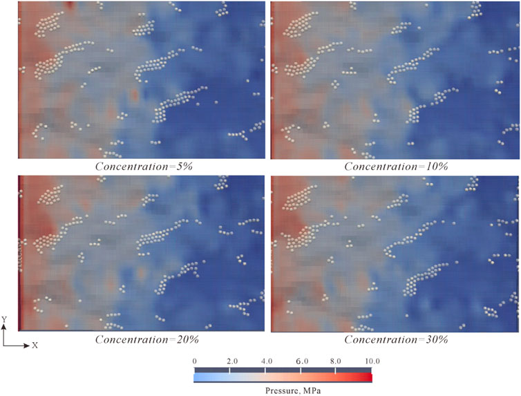
FIGURE 10. Plugging results at different particle concentrations in JRC15 (at the positive pressure difference of 10 MPa, friction coefficient of 0.9, and particle size/slit width of 0.9).
But it can be seen from the permeability retention rate and particle discharge rate curves (Figure 11) that the particle concentration has certain effect on the bridging process. From the particle discharge rate, it can be seen that the particle discharge rate rapidly reaches a stable peak with the increase of particle concentration, indicating that the increase of particle concentration accelerates the formation of particle bridging and plugging to some extent. It can be seen from the permeability retention rate curve, the smaller the particle concentration, the higher the permeability retention rate is, which also proves that the increase of concentration is conducive to bridging. But from the perspective of reservoir damage control, in the case that the fracture is not plugged at either high or low particle concentrations, the larger the particle concentration, the greater the number of particles invading the reservoir is, and the greater the damage to the reservoir is, which is not conducive to oil and gas discovery and production.
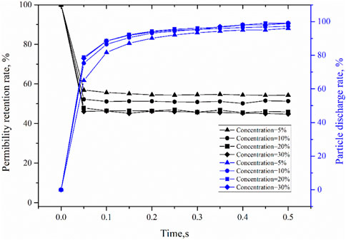
FIGURE 11. Variations of permeability retention rate and particle discharge rate of JRC15 with time at different particle concentrations.
In the actual drilling and completion process, particles are not homogeneous particles, but are combined by particles of several different sizes. In this study, the plugging effects of particles of three different sizes, A (0.2 mm), B (0.15 mm) and C (0.10 mm), in different formulations were simulated. The red (A), blue (C) and green (B) particles in Figure 12 represent static particles of different particle sizes. It can be seen from Figure 12 that the plugging layers formed by formulations 1# and 3# were thicker; but the plugging layers of all the formulations were similar in the front, where large particles were at the very fore-end, and the particles injected later unable to pass through the bridging layer formed by large particles accumulated to make the plugging layer thicker. The reason of the thicker plugging layer of formulation 1# is that it is easier for a large number of small particles to enter the fracture and accumulate; the reason of the thicker plugging layer of formulation 3# may be that in the case with higher content of large particles, if the overall concentration is maintained at a constant level, the particles are smaller in total number and thus likely to enter the middle-rear end of the fracture to accumulate.
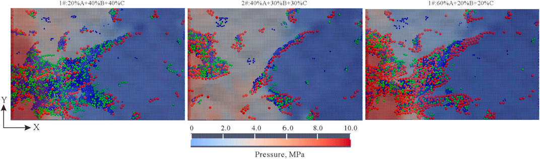
FIGURE 12. Plugging results of compound particles in JRC15 (at the positive pressure difference of 10 MPa and friction coefficient of 0.9).
The plugging layer is a porous medium formed by the accumulation of particles, and the relationship between the size distribution of the plugging particles and the absolute permeability (K) can be expressed by the Kozeny-Carman equation (Akgiray and Saatçı, 2001):
Where,
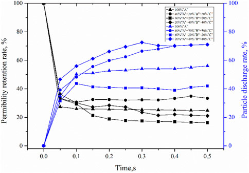
FIGURE 13. Variations of permeability retention rate and particle discharge rate of compound particles in JRC15.
The particle shape affects the particle bridging mode. In this study, the plugging results of different shaped particles were simulated by changing the friction coefficient. It can be seen from Figure 14 that the plugging layer became thicker with the increase of friction coefficient. At the same time, with the increase of friction coefficient, the particle bridging was still dominated by single particle bridging, and the plugging layers remained similar in the front-end morphology, but moved forward slightly in the front-end position. In other words, the more irregular the particle shape is, the thicker the plugging layer is, and the more easier it is for the particles to bridge.
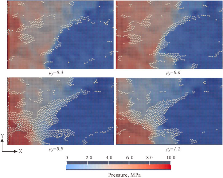
FIGURE 14. Plugging results of particles with different friction coefficients in JRC15.
Figure 15 shows the variations of permeability retention rate and particle discharge rate when plugging with particles of different friction coefficients. When the friction coefficient of the particles was 0.3, the final particle discharge rate stabilized at about 90% and the permeability retention rate at about 40% ultimately; while when the friction coefficient of the particles was 1.2, the particle discharge rate and permeability retention rate stabilized at only 30% and 30% at last. It can be seen that the larger the friction coefficient, the more easier it is for the particles to bridge and plug, and the tighter the plugging layer is. But the permeability retention rate of the fracture plugged with particles of 1.2 in friction coefficient was higher than that plugged with particles of 0.9 in friction coefficient. The possible reason for this is that the larger the friction coefficient, the more likely the particles form plugging at the fracture entrance, preventing the particles from entering deep into the fracture.
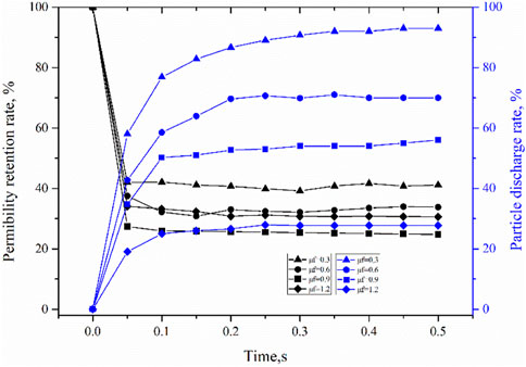
FIGURE 15. Variations of permeability retention rate and particle discharge rate of JRC 15 plugged with particles of different friction coefficients.
In this study, a coupled CFD-DEM method was used to simulate the plugging processes of propagating leaky fractures with particles, and the effects of positive pressure difference, fracture roughness, particle concentration, compound particle formulation, and particle shape on plugging mechanism of propagating fracture were analyzed based on distribution images of plugging particles, permeability retention rate and particle discharge rate. The following conclusions have been reached:
(1) When the positive pressure difference is less than 5 MPa, the particles can form stable bridging and plugging over a large area, but when the positive pressure difference is greater than 5 MPa, the particle bridging becomes difficult, and only slight bridging is formed in small parts of the fractures, unable to isolate the fluid and pressure completely. In the process of strengthening the wellbore by particle plugging, attention should be paid to the change of positive pressure difference. Positive pressure difference too large will lead to too large fracture aperture, so the particles cannot form effective plugging in the fracture; while positive pressure difference too small will lead to too small fracture aperture, so the particles cannot enter into the fracture to form plugging.
(2) In general, the particle bridging is basically not affected by particle concentration, which may be because that particle bridging is mostly dominated by single particle bridging and double particle bridging and multiple particle bridging are hard to come about.
(3) When the compound formula of large particles and small-medium particles is used to plug a fracture, the tighter the plugging layer, the lower the particle discharge rate is, which is conducive to fracture plugging and reservoir damage control.
(4) With the increase of friction coefficient of particles, the plugging layer becomes thicker, but the particle bridging is still dominated by single particle bridging, and the plugging layer remains basically the same in front-end morphology.
(5) For the wellbore strengthening approaches, such as stress cages, fracture tip sealing, etc., specific analysis should be carried out according to the occurrence of extended fractures. For example, for fractures with low roughness, the particles rarely form effective tight plugging in the middle of the fracture, so it is more suitable for fracture tip sealing; For the fracture with high roughness, if the positive pressure difference is controlled properly to ensure reasonable fracture extension, the particle plugging effect will be good, and the stress cage method is recommended for borehole strengthening.
The datasets presented in this study can be found in online repositories. The names of the repository/repositories and accession number(s) can be found in the article/Supplementary Material.
DM: Methodology, Software, Writing-Original draft preparation. LY: Conceptualization, Investigation. CK: Writing-Reviewing. DF: Data curation.
LY was employed by Oilfield Service Jianghan Corporation, SINOPEC. DM was employed by Jianghan Oilfield, SINOPEC. CK was employed by Chuanqing Drilling Engineering Company Limited CNPC. DF was employed by Tarim Oilfield CNPC
All claims expressed in this article are solely those of the authors and do not necessarily represent those of their affiliated organizations, or those of the publisher, the editors and the reviewers. Any product that may be evaluated in this article, or claim that may be made by its manufacturer, is not guaranteed or endorsed by the publisher.
Ahfir, N. D., Hammadi, A., Alem, A., Wang, H., Le Bras, G., and Ouahbi, T. (2017). Porous media grain size distribution and hydrodynamic forces effects on transport and deposition of suspended particles. J. Environ. Sci. 53, 161–172. doi:10.1016/j.jes.2016.01.032
Akgiray, Ö., and Saatçı, A. M. (2001). A new look at filter backwash hydraulics. Water Sci. Technol. Water Supply 1 (2), 65–72. doi:10.2166/ws.2001.0022
Barton, N., and Choubey, V. (1977). The shear strength of rock joints in theory and practice. Rock Mech. 10 (1), 1–54. doi:10.1007/BF01261801
Boutt, D. F., Grasselli, G., Fredrich, J. T., Cook, B. K., and Williams, J. R. (2006). Trapping zones: The effect of fracture roughness on the directional anisotropy of fluid flow and colloid transport in a single fracture. Geophys. Res. Lett. 33 (21), 1522–1534. doi:10.1029/2006GL027275
Brown, S. R. (1995). Simple mathematical model of a rough fracture. J. Geophys. Res. 100 (B4), 5941–5952. doi:10.1029/94JB03262
Cao, N., and Lei, G. (2019). Stress sensitivity of tight reservoirs during pressure loading and unloading process. Petroleum Explor. Dev. 46 (1), 138–144. doi:10.1016/S1876-3804(19)30013-8
Dai, J., and Grace, J. R. (2010). Blockage of constrictions by particles in fluid-solid transport. Int. J. Multiph. flow 36 (1), 78–87. doi:10.1016/j.ijmultiphaseflow.2009.08.001
Fan, C. H., Xie, H. B., Li, H., Zhao, S., Shi, X., Liu, J., et al. (2022). Complicated fault characterization and its influence on shale gas preservation in the southern margin of the sichuan basin, China, China. Lithosphere 2022, 8035106. doi:10.2113/2022/8035106
Feng, Q., Cha, L., Dai, C., Zhao, G., and Wang, S. (2020). Effect of particle size and concentration on the migration behavior in porous media by coupling computational fluid dynamics and discrete element method. Powder Technol. 360, 704–714. doi:10.1016/j.powtec.2019.10.011
Feng, Y., and Gray, K. E. (2016). A fracture-mechanics-based model for wellbore strengthening applications. J. Nat. Gas Sci. Eng. 29, 392–400. doi:10.1016/j.jngse.2016.01.028
Feng, Y., Jones, J. F., and Gray, K. E. (2016). A review on fracture-initiation and-propagation pressures for lost circulation and wellbore strengthening. SPE Drill. Complet. 31 (2), 134–144. doi:10.2118/181747-PA
Feng, Y., Li, G., Meng, Y., and Guo, B. (2018). A novel approach to investigating transport of lost circulation materials in rough fracture. Energies 11 (10), 2572. doi:10.3390/en11102572
Huang, H., Babadagli, T., Li, H., Develi, K., and Zhou, D. (2020). A visual experimental study on proppants transport in rough vertical fractures. Int. J. Rock Mech. Min. Sci. 134, 104446. doi:10.1016/j.ijrmms.2020.104446
Khan, H. J., Mirabolghasemi, M. S., Yang, H., Prodanovic, M., DiCarlo, D. A., and Balhoff, M. T. (2017). Study of formation damage caused by retention of bi-dispersed particles using combined pore-scale simulations and particle flooding experiments. J. Petroleum Sci. Eng. 158, 293–308. doi:10.1016/j.petrol.2017.08.061
Koyama, T., Li, B., Jiang, Y., and Jing, L. (2008). Numerical simulations for the effects of normal loading on particle transport in rock fractures during shear. Int. J. Rock Mech. Min. Sci. 45 (8), 1403–1419. doi:10.1016/j.ijrmms.2008.01.018
Kuzmina, L. I., Osipov, Y. V., and Zheglova, Y. G. (2018). Analytical model for deep bed filtration with multiple mechanisms of particle capture. Int. J. Non-linear Mech. 105, 242–248. doi:10.1016/j.ijnonlinmec.2018.05.015
Li, H. (2022). Research progress on evaluation methods and factors influencing shale brittleness: A review. Energy Rep. 8, 4344–4358. doi:10.1016/j.egyr.2022.03.120
Li, S., Kang, Y., You, L., Li, D., and Lian, Z. (2014). Experimental and numerical investigation of multiscale fracture deformation in fractured-vuggy carbonate reservoirs. Arab. J. Sci. Eng. 39 (5), 4241–4249. doi:10.1007/s13369-014-1018-6
Li, Y., Kang, Z. J., Xue, Z. J., and Zheng, S. (2018). Theories and practices of carbonate reservoirs development in China. Petroleum Explor. Dev. 45 (4), 712–722. doi:10.1016/S1876-3804(18)30074-0
Li, H., Tang, H. M., Qin, Q. R., Zhou, J., Qin, Z., Fan, C., et al. (2019). Characteristics, formation periods and genetic mechanisms of tectonic fractures in the tight gas sandstones reservoir: A case study of xujiahe formation in YB area, sichuan basin, China. J. Petroleum Sci. Eng. 178, 723–735. doi:10.1016/j.petrol.2019.04.007
Li, J., Qiu, Z., Zhong, H., Zhao, X., and Huang, W. (2020). Coupled CFD-DEM analysis of parameters on bridging in the fracture during lost circulation. J. Petroleum Sci. Eng. 184, 106501. doi:10.1016/j.petrol.2019.106501
Li, J., Li, H., Yang, C., Wu, Y., Gao, Z., and Jiang, S. (2022a). Geological characteristics and controlling factors of deep shale gas enrichment of the Wufeng-Longmaxi Formation in the southern Sichuan Basin, China. Lithosphere 2022, 4737801. doi:10.2113/2022/4737801
Li, H., Zhou, J. L., Mou, X. Y., Guo, H., Wang, X., An, H., et al. (2022b). Pore structure and fractal characteristics of the marine shale of the longmaxi formation in the changning area, southern sichuan basin, China. Front. Earth Sci. 10, 1018274. doi:10.3389/feart.2022.1018274
Moore, C. H., and Wade, W. J. (2013). Carbonate reservoirs: Porosity and diagenesis in a sequence stratigraphic framework. Newnes. London, UK.
Ogilvie, S. R., Isakov, E., and Glover, P. (2006). Fluid flow through rough fractures in rocks. II: A new matching model for rough rock fractures. Earth Planet. Sci. Lett. 241 (4), 454–465. doi:10.1016/j.epsl.2005.11.041
Tse, R., and Cruden, D. M. (1979). Estimating joint roughness coefficients. Int. J. Rock Mech. Min. Sci. Geomechanics Abstr. 16 (5), 303–307. doi:10.1016/0148-9062(79)90241-9
Walsh, J. B. (1981). Effect of pore pressure and confining pressure on fracture permeability. Int. J. Rock Mech. Min. Sci. Geomechanics Abstr. 18 (5), 429–435. doi:10.1016/0148-9062(81)90006-1
Wang, G., and Pu, X. (2014). Discrete element simulation of granular lost circulation material plugging a fracture. Part. Sci. Technol. 32 (2), 112–117. doi:10.1080/02726351.2013.829546
WuFan, J. Y. R. F., Wu, F., and Li, C. (2019). Combining large-sized model flow experiment and NMR measurement to investigate drilling induced formation damage in sandstone reservoir. J. Petroleum Sci. Eng. 176, 85–96. doi:10.1016/j.petrol.2019.01.005
Xu, C., You, Z., Kang, Y., and You, L. (2018). Stochastic modelling of particulate suspension transport for formation damage prediction in fractured tight reservoir. Fuel 221, 476–490. doi:10.1016/j.fuel.2018.02.056
Yang, Y., Tao, L., Yang, H., Iglauer, S., Wang, X., Askari, R., et al. (2020). Stress sensitivity of fractured and vuggy carbonate: An X-ray computed tomography analysis. J. Geophys. Res. Solid Earth 125 (3), e2019JB018759. doi:10.1029/2019JB018759
Zeng, J., Li, H., and Zhang, D. (2016). Numerical simulation of proppant transport in hydraulic fracture with the upscaling CFD-DEM method. J. Nat. Gas Sci. Eng. 33, 264–277. doi:10.1016/j.jngse.2016.05.030
Zhang, G., Gutierrez, M., and Chao, K. (2019a). Hydrodynamic and mechanical behavior of multi-particle confined between two parallel plates. Adv. Powder Technol. 30 (2), 439–450. doi:10.1016/j.apt.2018.11.023
Zhang, J., Wei, C., Ju, W., Yan, G., Lu, G., Hou, X., et al. (2019b). Stress sensitivity characterization and heterogeneous variation of the pore-fracture system in middle-high rank coals reservoir based on NMR experiments. Fuel 238, 331–344. doi:10.1016/j.fuel.2018.10.127
Zhu, B., Tang, H., Zhao, F., and Tang, H. (2020). Numerical simulation of particulate suspension transport and permeability impairment in an actual rough fracture under normal stresses. Energy Sci. Eng. 8 (4), 1165–1180. doi:10.1002/ese3.576
Keywords: propagating fractures, CFD-DEM, particle, stress cage, plugging, carbonate reservoir
Citation: Yanqian L, Mengling D, Kunchi C and Feixu D (2023) Study on particle plugging in propagating fractures based on CFD-DEM. Front. Earth Sci. 10:1037532. doi: 10.3389/feart.2022.1037532
Received: 06 September 2022; Accepted: 21 September 2022;
Published: 06 January 2023.
Edited by:
Hu Li, Southwest Petroleum University, ChinaCopyright © 2023 Yanqian, Mengling, Kunchi and Feixu. This is an open-access article distributed under the terms of the Creative Commons Attribution License (CC BY). The use, distribution or reproduction in other forums is permitted, provided the original author(s) and the copyright owner(s) are credited and that the original publication in this journal is cited, in accordance with accepted academic practice. No use, distribution or reproduction is permitted which does not comply with these terms.
*Correspondence: Dong Mengling, MjQ3Mjg3MjYwM0BxcS5jb20=
Disclaimer: All claims expressed in this article are solely those of the authors and do not necessarily represent those of their affiliated organizations, or those of the publisher, the editors and the reviewers. Any product that may be evaluated in this article or claim that may be made by its manufacturer is not guaranteed or endorsed by the publisher.
Research integrity at Frontiers
Learn more about the work of our research integrity team to safeguard the quality of each article we publish.