 Tiansheng Li1,2
 Ziquan Chen
 Zihan Zhou
95% of researchers rate our articles as excellent or good
Learn more about the work of our research integrity team to safeguard the quality of each article we publish.
Find out more
ORIGINAL RESEARCH article
Front. Earth Sci. , 16 January 2023
Sec. Environmental Informatics and Remote Sensing
Volume 10 - 2022 | https://doi.org/10.3389/feart.2022.1031985
This article is part of the Research Topic Advances and Applications of Artificial Intelligence and Numerical Simulation in Risk Emergency Management and Treatment View all 22 articles
Tunnel construction in high geo-stress strata faces the risk of extreme natural disasters such as large squeezing deformation and rockburst. Therefore, it is of great significance to adopt a high-precision inversion method to investigate the distribution law of in situ stress in the tunnel site area. In this paper, the in situ stress inversion research was carried out based on a plateau tunnel with a buried depth of more than 1000 m. The idea of improving the inversion accuracy by unifying displacement constraints was proposed by aiming at the defects of the traditional method on the boundary conditions. Furthermore, the impact of the constant term in the regression model on the fitting accuracy was discussed. According to the inversion method with optimized fitting conditions, the in situ stress distribution characteristics in the tunnel site area were obtained, and the variation law of the in situ stress near the fault zone was discussed. The results showed that after unifying displacement constraints, the comprehensive inversion accuracy comprehensive indicator reflecting the inversion accuracy decreased from 15.291 to 12.895, indicating that the inversion error was effectively controlled. Whether the constant term should be retained had a random effect on the inversion accuracy, so it was recommended that this issue be independently verified when fitting the data. When approaching the inner side of the fault from the outer side, the in situ stress first increased slightly and then decreased significantly. Moreover, the wider the fault impact zone and the farther the fault distribution distance, the more significant the amplitude of stress change, e.g., the maximum amplitude of stress change reached 9.0 MPa. In addition, the in situ stress orientation near the fault can be significantly deflected. And the wider the fault impact zone, the more pronounced the deflection.
Affected by the intense tectonic movements of the Indian Ocean and the Eurasian plates, the Qinghai-Tibet Plateau has natured many faults and high tectonic in situ stress (Zhang D. L. et al., 2022; Wang et al., 2022). Tunnel project constructed in this stratum faces the significant risk of geological disasters, such as squeezing large deformation disasters in soft rock (Hu et al., 2022; Liu et al., 2022) and rockburst disasters in hard rock (Fan et al., 2021; Zhang H. et al., 2022). Therefore, it is significant to investigate the in situ stress distribution law in deep-buried tunnels crossing fault zone strata to guide the structural design and prevent and control geological disasters.
Since there are no conditions for measuring inside the tunnel in the geological exploration stage, the hydraulic fracturing method is the only means to measure the in situ stress in this stage (Zhang et al., 2014). The multiple linear regression method developed based on the elastic stress assumption of the hydraulic fracturing method is one of the commonly used methods for in situ stress inversion (Zhang et al., 2012). Figueiredo et al. (2014) used the multiple linear regression method to reveal that the in situ stress of the granite formation of a hydropower station in northern Portugal was controlled by self-weight stress and shear stress. Li et al. (2015) proposed the local least squares regression measure to improve the inversion accuracy based on the multiple linear regression method and applied it to a dam project. Meng et al. (2020) adopted the multiple linear regression method to put forward the idea of in situ stress inversion for high geo-temperature tunnels considering the temperature stress component. Based on the multiple linear regression method, Xu et al. (2021) proposed an in situ stress inversion system that comprehensively considered information such as geological tectonic background and topography. Meng et al. (2021) discussed the effect of using ridge regression to improve the inversion accuracy of the multiple linear regression method. However, the displacement constraints of each calculation condition in these applications are not strictly consistent, likely leading to significant inversion errors.
Some scholars have revealed the in situ stress distribution law in tectonic strata based on the inversion results. Han et al. (2016) found no direct linear relationship between the horizontal tectonic stress and the burial depth in the syncline, and the stress orientation was deflected inside and outside the syncline. Li G. et al. (2020) studied the distribution law of in situ stress in gully strata relying on a hydropower station in the mountainous area of southwest China, and the conclusion showed that buried depth had a positive effect on the in situ stress level. Based on the in situ stress inversion results of tunnel engineering of the Sichuan-Tibet Railway, Li X. P. et al. (2020) concluded that the in situ stress dropped suddenly inside the fault. Ning et al. (2021) studied the in situ stress distribution characteristics in the valley area considering geological tectonic movement and river erosion and believed that the stress relaxation effect occurred in the unloading and rebound area of the slope. Zhou et al. (2022) studied the in situ stress distribution law of the intrusive rock strata through the segmented inversion method and believed that there was a sudden stress change phenomenon at the intrusive rock interface. However, although these studies have investigated the in situ stress distribution of some structural strata, few studies have systematically analyzed the in situ stress distribution characteristics of dense fault zones.
Relying on a deep-buried Plateau tunnel in Southwest China, this paper first analyzed the optimization effect of unified displacement constraints on inversion accuracy. Then, the random effect of the constant term in the regression model on the inversion error was discussed. The in situ stress distribution law when the tunnel crosses the fault zone was revealed based on the multiple linear regression method with optimized fitting conditions. Furthermore, the change law of the value and orientation of the in situ stress near the fault was emphatically discussed.
The plateau tunnel is located on the eastern edge of the Qinghai-Tibet Plateau, passing through Zheduo Mountain, the first high mountain in Sichuan Province to enter Tibet. Its south is the Indian Ocean plate, and its north is the Eurasian plate. The plate compression has created an active neotectonic movement in this area (Figure 1). Affected by the intense geological tectonic action, the tunnel site area is densely covered with mountains and ravines. Figure 1B shows the typical plateau landform characteristics of the tunnel site area, and its surface elevation is about 3460–4730 m. In addition, the strong stratigraphic cutting action formed the famous Y-shaped active fault zone in southwest China near the tunnel site. The tunnel is located on the Xianshuihe active fault zone on the northwest side of this area (Figure 1D).
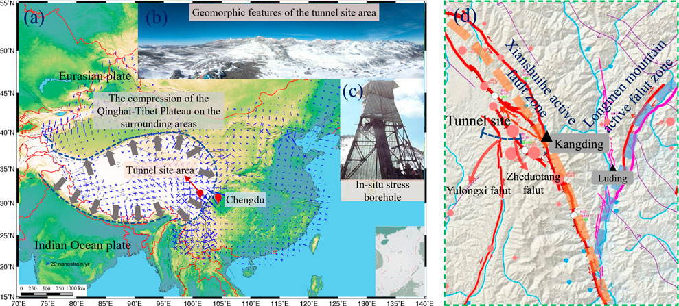
FIGURE 1. Geological background of the tunnel: (A) stress field of China; (B) plateau landform characteristics; (C) in situ stress measurement; (D) main fault zone around tunnel site.
The tunnel entrance is in Zheduotang Village, and its exit is in Shuiqiao Village. Its total length and maximum buried depth are about 20.8 km and 1215 m, respectively (Figure 2). The strata traversed by the tunnel include quartz sandstone, biotite adamellite, and slate. Affected by the Xianshuihe active fault zone, 12 faults are distributed in the tunnel site area. Among them, the Zheduotang fault covers the range of 3–4 km in the entrance, which is only represented by the actual strata. Among them, the faults with a wider impact range include the Zheduotang branch fault with a width of 302 m, the Jinlongsi-mozigou fault with a width of 198 m, the F15 fault with a width of 296 m, and the Yulongxi fault with a width of 614 m. Besides, the rest of the faults are roughly 100 m wide.
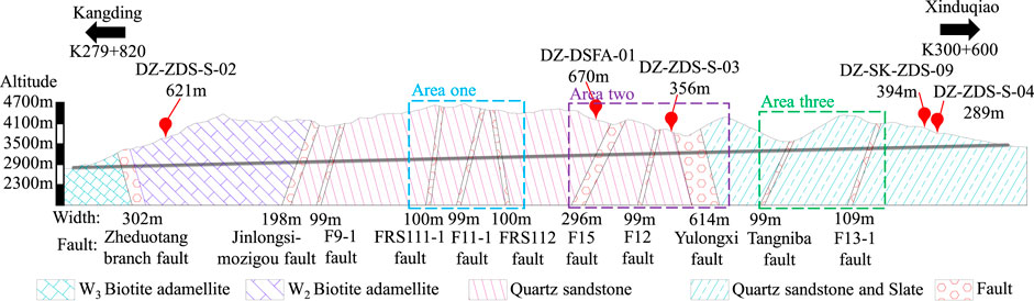
FIGURE 2. Longitudinal profile of the tunnel.
The large buried depth and complex tectonic geological environment are typic features of the tunnel. Generally, in addition to the self-weight stress, there is a nonnegligible horizontal tectonic stress in the strata with active geological movement (Yuan et al., 2022). Furthermore, in this geological environment, the horizontal tectonic stress is even greater than the vertical self-weight stress (Zhao et al., 2021). In order to investigate the in situ stress distribution characteristics in the tunnel site area, field measurement was carried out by the hydraulic fracturing method during the geological exploration stage. There are five in situ stress boreholes in total. Among them, the maximum depth of DZ-ZDS-S-02, DZ-DSFA-01, DZ-ZDS-S-03, DZ-SK-ZDS-09, and DZ-ZDS-S-04 boreholes is 621 m, 670 m, 356 m, 394 m, and 289 m, respectively (Figure 2). Except for the DZ-DSFA-01 borehole, which has five measuring points, the other boreholes have four.
Figure 3 shows the measured in situ stress at different measuring points of each borehole. It can be seen that for a single borehole, the in situ stress of each measuring point increases almost linearly with the increase of the buried depth. Especially the vertical stress (σV), the measured in situ stress of all boreholes maintains the same linear growth relationship. On the other hand, the maximum horizontal principal stress (σH) and the minimum horizontal principal stress (σh) between different boreholes show an apparent nonlinear relationship. Among them, the DZ-ZDS-S-02, DZ-SK-ZDS-09, and DZ-ZDS-S-04 boreholes are particularly significant. Comparing Figure 2, it can be seen that these three boreholes are located on both sides of the tunnel site area and are far away from the two middle boreholes. Therefore, there are certain differences in the distribution characteristics of in situ stress in different local areas.
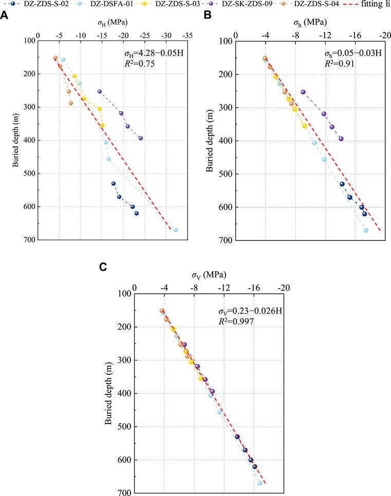
FIGURE 3. Measured in situ stress: (A) maximum horizontal principal stress; (B) minimum horizontal principal stress; (C) vertical stress.
To further demonstrate the linear relationship between each stress component and the buried depth, Figure 3 also shows the linear fitting results of the measured data. Among them, the linear relationship between σV and burial depth (H) is the most significant, and its goodness of fit R2 reaches 0.997. Secondly, σh also has a good linear correlation with buried depth, and the corresponding goodness of fit R2 is 0.91. In addition, the linear correlation between σH and burial depth is the weakest, and the corresponding goodness of fit R2 is only 0.75.
The buried depth range of the DZ-ZDS-S-02, DZ-DSFA-01, DZ-ZDS-S-03, DZ-SK-ZDS-09, and DZ-ZDS-S-04 boreholes is 530–620 m, 157–670 m, 206–355 m, 253–394 m, and 151–288 m, respectively. The corresponding σH range of each borehole is −17.73 ∼ −23.08 MPa, −6.02 ∼ −32.20 MPa, −8.47 ∼ −15.11 MPa, −14.53 ∼ −24.06 MPa, and −4.09 ∼ −7.72 MPa, respectively, the σh range of each borehole is −14.30 ∼ −17.32 MPa, −4.11 ∼ −17.43 MPa, −5.38 ∼ −9.17 MPa, −9.01 ∼ −14.06 MPa, and −3.92 ∼ −7.46 MPa, respectively, and the σV range of each borehole is −13.83 ∼−16.12 MPa, −3.90 ∼−16.84 MPa, −5.18 ∼−8.91 MPa, −6.74 ∼−10.37 MPa, and −3.66 ∼ −7.08 MPa, respectively.
The in situ stress gradient in the tunnel site can be obtained by dividing the stress increment by the buried depth increment. The calculation indicates that the average increment gradients per 100 m buried depth of σH, σh, and σV are 4.32 MPa, 2.81 MPa, and 2.53 MPa, respectively. In other words, σH is 1.54 times σh and 1.71 times σV. Hence, the in situ stress field of the tunnel presents σH > σh > σV. This indicates that the horizontal tectonic movement of the strata in this area is strong, and the in situ stress is dominated by the horizontal principal stress.
Since there is no field condition for measuring in situ stress inside the tunnel, the measurement by the hydraulic fracturing method is the only means in the geological exploration stage (Zhang et al., 2014). The principle of the hydraulic fracturing method indicates that its stress components are derived based on elastic assumptions (Pei et al., 2016). That is to say, the measured in situ stresses obtained by the hydraulic fracturing method are all elastic stresses. Based on this, the multiple linear regression method using the least squares optimization criterion according to the principle of linear superposition is widely used in the field of in situ stress inversion. In short, the inversion principle of the multiple linear regression method is to approximate the observed value through the regression value to solve the regression coefficient. In other words, the residual sum of squares between the regression value and the observed value is minimized based on the least squares method. The regression model of the multiple linear regression method is as follows:
where
The residual sum of squares, i.e.,
where
Furthermore, the regression coefficient can be obtained by taking the minimum value of the residual sum of squares based on the least squares method. The solution equation is as follows:
where the left matrix is a symmetric matrix.
The regression model representing the in situ stress field in the tunnel site area can be obtained by putting
The multiple linear regression method has the characteristics of high computational efficiency and unique output solution, so it is widely used in engineering. However, two issues are not clearly agreed upon in the practical application of this method. One is that the boundary conditions of the calculation conditions have not been unified, and the other is that multiple linear regression can be performed even if the constant term a0 is deleted. Engineering practices show that these two issues are very likely to impact the inversion accuracy. Therefore, the multiple linear regression method urgently needs to be improved in these two aspects.
Import the geological plan of the tunnel site area into Surfer software to obtain the three-dimensional coordinate information of the surface. Input this information into ANSYS finite element software to establish the top surface of the model. The Z direction of the model includes the range of 3000 m below the tunnel portal, the Y direction is 4000 m, and the X direction is 21,000 m. As shown in Figure 4, the tunnel axis is basically located in the central area of the three-dimensional numerical model. In order to avoid the deformed grid caused by the irregular surface, the grid refinement process is carried out in some local areas. In the end, the total number of meshes exceeds six million. The physical and mechanical parameters of rock mass were derived from geological exploration data, as shown in Table 1. Literature researches shows that the value range of rock mass parameters around tunnel areas in previous studies is basically consistent with that in Table 1 (Meng et al., 2021; Zhou et al., 2022). In addition, these rock mass parameters are generally consistent with the recommended values in the Code for Design of Railway Tunnel (National Railway Administration of PRC 2017).
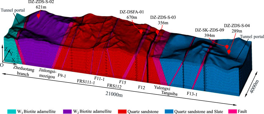
FIGURE 4. Three-dimensional numerical model of the tunnel site area.
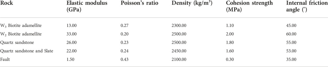
TABLE 1. Physical and mechanical parameters of the rock masses.
For the fault simulation method in the numerical model, the Boolean operation was firstly used to cut the model to form the impact area of the fault fracture zone. Then, the following assumptions were made on the mechanical parameters and contact relationship of the fault based on its genesis. Taking strike-slip faults as an example, Figure 5 shows the genetic mechanism of the fault. When the stress difference exceeds the strength level, the original rock mass begins to fracture. A fault plane, i.e., the fault plane where the two fault walls slide relative to each other, is gradually formed with the development of micro-fractures. Once the fault plane is formed and the stress difference exceeds the frictional resistance, the two fault walls begin to slide relative to each other, forming a fault. With the sliding of the fault, the surrounding rock mass is fractured under the action of friction and shear (Li, 2022). Based on the above mechanism, it was first assumed that the closer to the fault plane, the more fragmented the rock mass. Then the physical and mechanical parameters of the rock mass inside the fault satisfy Eqn. 4.
where
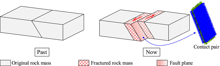
FIGURE 5. Genetic mechanism of the fault: (A) original rock mass; (B) fault.
Secondly, it was assumed that the fault plane was located in the middle of the fractured rock mass (Li et al., 2017), and its frictional constitutive relation adopted the Coulomb friction-slip criterion.
where
The contact pair in ANSYS software was used to simulate the above fault frictional relationship, shown in Figure 5B.
Due to the coordinate system of the measured stress being different from that of the three-dimensional numerical model, the coordinate system of the measured stress needs to be transformed before inversion. The coordinate transformation formula in elastic mechanics is as follows:
where
The measured stress after coordinate transformation is shown in Table 2.
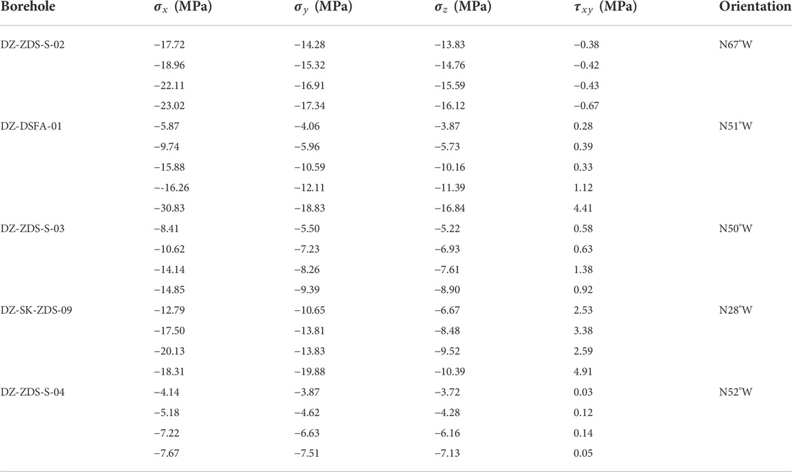
TABLE 2. Measured in situ stresses after coordinate transformation.
Apply boundary conditions simulating self-weight and different tectonic actions to the numerical model to obtain the calculated stress, and then use the inversion principle to obtain the regression model of the in situ stress field in the tunnel site area. Common boundary conditions include self-weight stress (Figure 6A), 1 MPa uniform load in the X direction (Figure 6B), 1 MPa uniform load in the Y direction (Figure 6C), unit shear load in the XOY plane (Figure 6D), triangular gradient load in the X direction (Figure 6E), and triangular gradient load in the Y direction (Figure 6F). Among them, the XOY plane adopts the method of forced displacement to simulate the shear effect of plane structure (Meng et al., 2021), and the triangular load is applied with a gradient of 1 kPa/m.
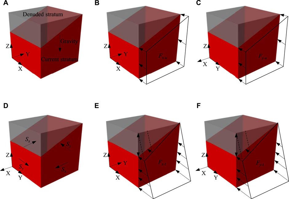
FIGURE 6. Boundary conditions of multiple linear regression method: (A) self-weight stress; (B) uniform load in X direction; (C) uniform load in Y direction; (D) shear load in XOY plane; (E) triangular gradient load in X direction; (F) triangular gradient load in Y direction.
The principle of linear superposition has strict preconditions, one of which is that the material must satisfy Hooke’s law, i.e., the mechanical constitutive model of the material is linear elastic. The second is that the boundary conditions of each load condition need to be consistent. In this way, the stress superposition value of each load condition can be equal to the stress value after all loads are applied simultaneously. However, due to the failure to strictly adhere to the boundary requirements of the linear superposition principle, the error of the multiple linear regression method will increase in practical applications. Specifically, the boundary conditions in Figure 6 were transformed into those in Figure 7A (Li et al., 2015). It can be seen from Figure 7A that the displacement constraints under each calculation condition are different. Nevertheless, the essential requirement of the linear superposition principle is that the displacement constraints of each calculation condition need to be consistent. The main reason for this phenomenon is that some scholars assume that the opposite boundary is fixedly constrained when applying tectonic loads (Meng et al., 2020; Zhou et al., 2022). Then, the boundary conditions strictly following the linear superposition principle are shown in Figure 7B. It can be seen from Figure 7B that the displacement constraint conditions of all calculation conditions are consistent. The displacement constraint range of each working condition includes a boundary surface parallel to the X direction, a boundary surface parallel to the Y direction, and the bottom surface.
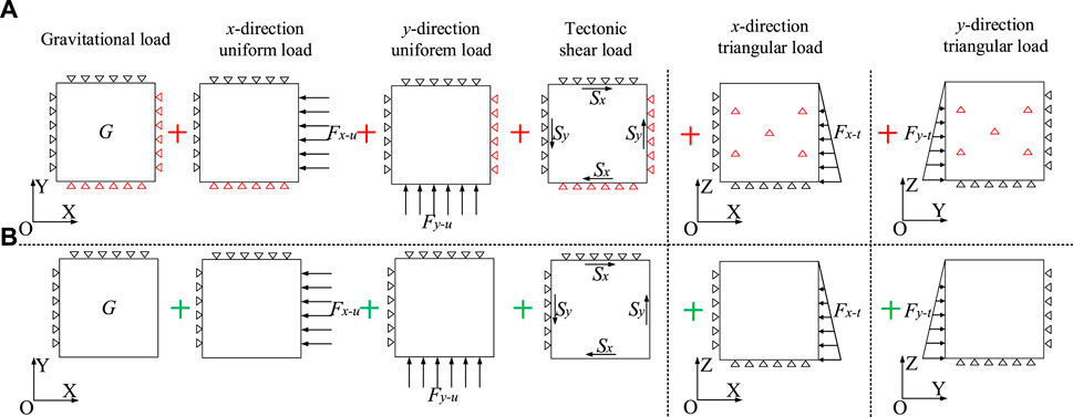
FIGURE 7. Linear superposition principle in multiple linear regression method: (A) not unified displacement constraints; (B) unified displacement constraints.
In order to verify the optimization effect of unified displacement constraints condition on the inversion accuracy, the regression models of two boundary types were solved according to the principle of multiple linear regression. Eqn .9 corresponds to the boundary condition in Figure 7A, i.e., not unified displacement constraints (NUDC-C method), and Eqn. 10 corresponds to the boundary condition in Figure 7B, i.e., unified displacement constraints (UDC-C method). Among them, the last C at the abbreviation represents whether the regression model has a constant term, which will be discussed in the next section.
where
Due to space limitations, only
where
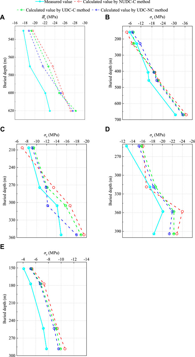
FIGURE 8. Comparison of the measured values and the inversion values: (A) DZ-ZDS-S-02 borehole; (B) DZ-DSFA-01 borehole; (C) DZ-ZDS-S-03 borehole; (D) DZ-SK-ZDS-09 borehole; (E) DZ-ZDS-S-04 borehole.
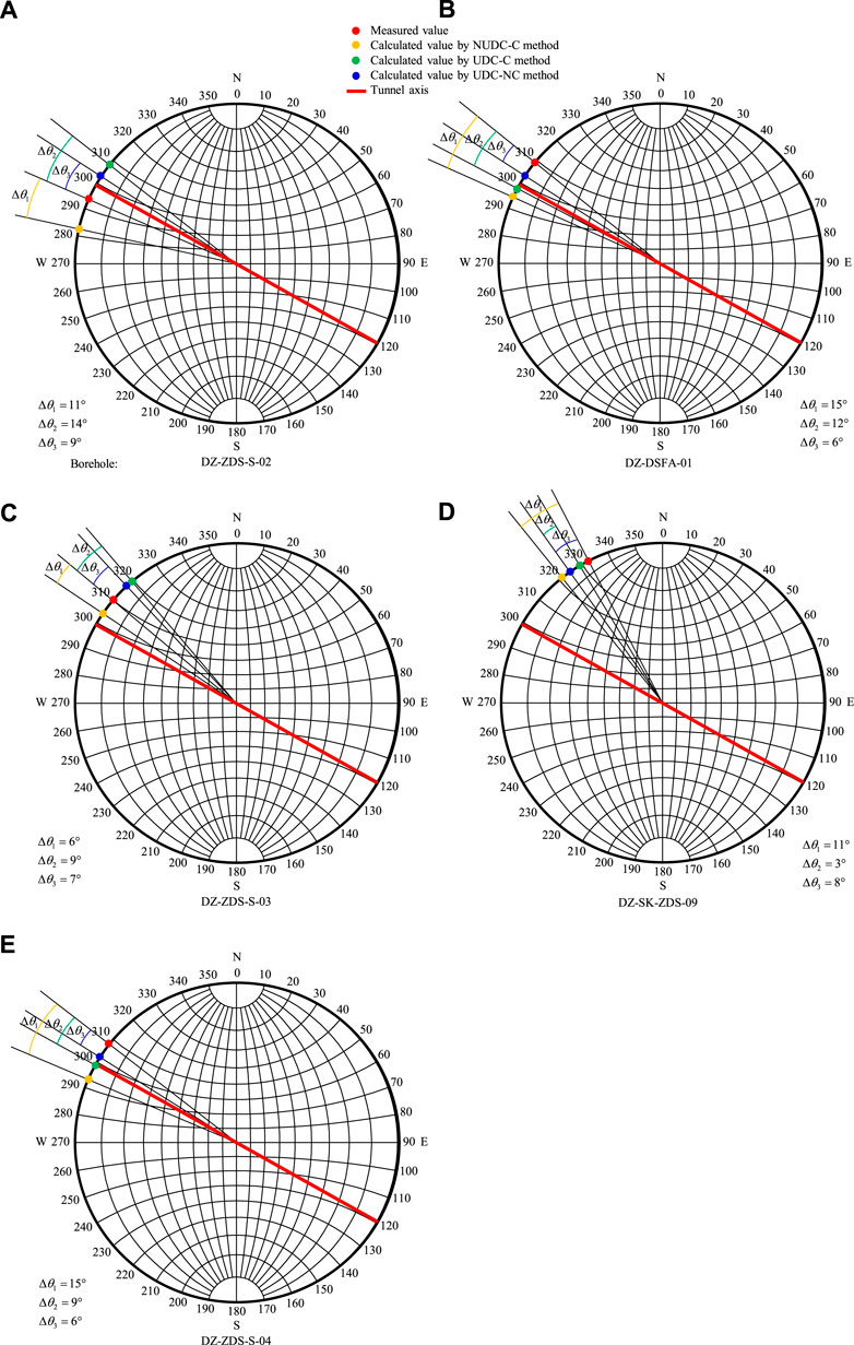
FIGURE 9. Comparison of the measured orientations and the inversion orientations: (A) DZ-ZDS-S-02 borehole; (B) DZ-DSFA-01 borehole; (C) DZ-ZDS-S-03 borehole; (D) DZ-SK-ZDS-09 borehole; (E) DZ-ZDS-S-04 borehole.
It can be seen from Figure 8 that the inversion results of the NUDC-C method and the UDC-C method generally maintain a consistent distribution law with the measured values. However, especially at DZ-ZDS-S-03, DZ-SK-ZDS-09, and DZ-ZDS-S-04 boreholes, the distribution law of the inversion results of the UDC-C method is more similar to the measured values. At the same time, the absolute error of the UDC-C method is smaller than that of the NUDC-C method for all other measuring points except for the measuring points with 620 m buried depth in the DZ-ZDS-S-02 borehole, and 319 m buried depth in the DZ-SK-ZDS-09 borehole. Figure 9 also shows that the inversion effect of the UDC-C method is better than that of the NUDC-C method. Except for the DZ-ZDS-S-02 and DZ-ZDS-S-03 boreholes, where the absolute error of the UDC-C method increases by 3°, the absolute errors of the other boreholes decrease significantly. For example, from the NUDC-C method changed to the NDC-C method, the absolute error of the DZ-DSFA-01 borehole is reduced from 15° to 12°, and that of the DZ-SK-ZDS-09 borehole is reduced from 11° to 3°, and that of the DZ-ZDS-S-04 borehole is reduced from 15° to 9°.
Furthermore, the statistical indicators, including the relative error (
where
where
Table 3 lists the statistical indicators of
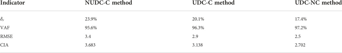
TABLE 3. Statistical indicators of σx for different inversion methods.
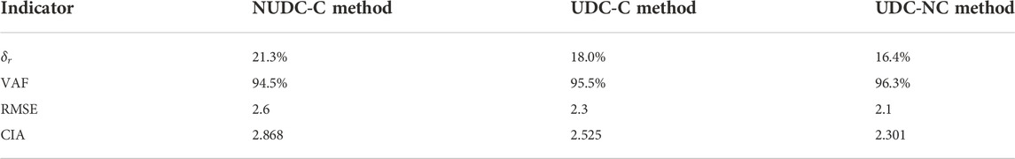
TABLE 4. Overall statistical indicators of the stress value for different inversion methods.
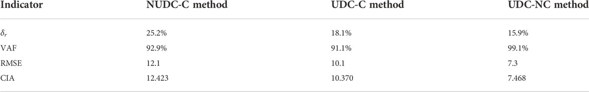
TABLE 5. Overall statistical indicators of the stress orientation for different inversion methods.

TABLE 6. Comprehensive CIA indicators for different inversion methods.
The multiple linear regression method also has an uncertain factor in the data fitting: whether the regression model should contain the constant term a0. Traditional practice generally includes the constant term a0 (Li et al., 2015; Meng et al., 2021; Zhou et al., 2022), in which case the regression model is Eqn. 1. However, some regression models do not contain the constant term (Figueiredo et al., 2014; Meng et al., 2020; Xu et al., 2021), in which case the regression model is Eqn. 17. In fact, whether to include a constant term is just a matter of choice between the two fitting methods. However, this choice will likely affect the accuracy level of the inversion results. Figure 10 shows the effect of the constant term on the data fit. Obviously, the sum of the errors in Figure 10A, i.e., does not contain a constant term, and that in Figure 10B, i.e., contains a constant term, are probably not equal. Moreover, it is impossible to know in advance which method is more accurate. Therefore, it is necessary to judge whether the constant term should be included before determining the final regression model. Based on this, taking the model with the unified displacement constraints as the standard, the accuracy difference between the inversion methods with a constant term (UDC-C method) and with no constant term (UDC-NC method) is further discussed.
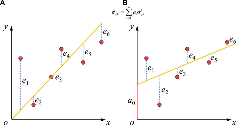
FIGURE 10. Influence of the constant term on data fit: (A) not contain a constant term; (B) contain a constant term.
According to the same inversion principle, the data fitting is performed after removing the constant term, and the obtained regression model is as follows:
The inversion results of
It should be emphasized that although the inversion accuracy of the UDC-NC method in this tunnel engineering is higher than that of the UDC-C method, it does not prove that the fitting method with no constant term will obtain more accurate inversion results. In fact, according to the fitting principle in Figure 10, the influence of the constant term on the inversion accuracy is random. In other words, higher inversion accuracy may appear in regression models with no constant terms or regression models with a constant term. Therefore, it is recommended that the effect of the constant term on the inversion error must be discussed before determining the regression model.
Based on the above improvement measures for the multiple linear regression method in terms of fitting conditions, the optimized process of in situ stress inversion is summarized as follows (Figure 11). The first step is to collect the geological information, geographic information, rock mass mechanical parameters, and measured in situ stresses. The second step is to build a three-dimensional numerical model based on the information. The third step is to keep the displacement constraints of the model consistent under each working condition. The fourth step is to discuss the effect of the constant term on accuracy. The fifth step is to select the regression model with higher inversion accuracy to obtain the in situ stress field in the tunnel site area.
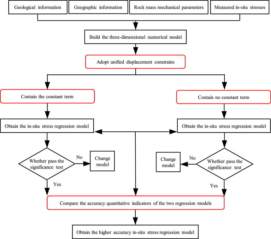
FIGURE 11. Optimized process of the in situ stress inversion.
Affected by the stress concentration effect at the model boundary, the data about 2000 m on both sides of the tunnel axis should be excluded. Figure 12 shows the in situ stress distribution in the range of the tunnel axis K281+620 ∼ K298+820. From a macro perspective, the
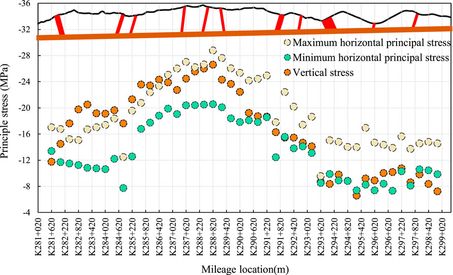
FIGURE 12. Distribution of the in situ stress along tunnel axis.
On the other hand, their distribution laws are different from the perspective of local areas. Taking the mileage K286+420 as the boundary, the stress distribution law on the left side shows that
In addition, Figure 12 also shows that there are large fluctuations in stress near the fault. This phenomenon is particularly significant in mileage K284+820 and mileage K291+620. For example, at mileage K284+820, the
Select the F11-1 fault in Area one, the Yulongxi fault in Area two, and the F13-1 fault in Area three to analyze the in situ stress distribution law in the fault zone (Figure 13). In general, on the outside of the fault, the in situ stress slightly increases as it approaches the fault, and inside the fault, the in situ stress decreases as it approaches the fault plane. For example, while approaching the fault from outside,
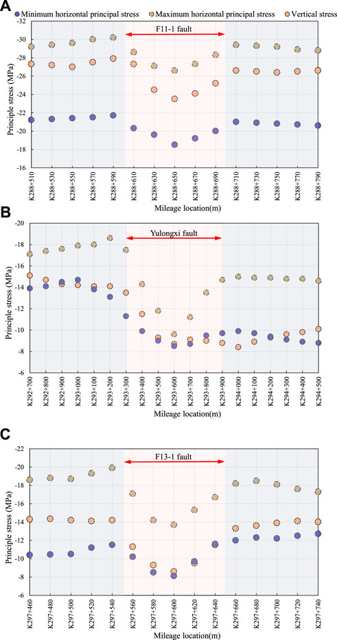
FIGURE 13. Distribution characteristics of in situ stress value inside and outside the fault: (A) F11-1 fault; (B) Yulongxi fault; (C) F13-1 fault.
Figure 14 shows the variation of
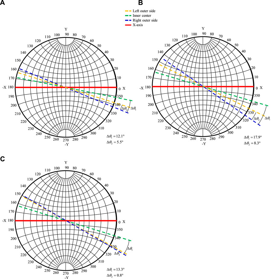
FIGURE 14. Distribution characteristics of in situ stress orientation inside and outside the fault: (A) F11-1 fault; (B) Yulongxi fault; (C) F13-1 fault.
In this paper, an inversion method with unified displacement constraints was proposed to improve the inversion accuracy. On this basis, the influence of the constant term in the regression model on the inversion accuracy was discussed, and the specific process of the inversion method with optimized fitting conditions was proposed. By using this optimized method, the in situ stress field distribution law between the densely distributed faults in the tunnel site area was revealed. The main conclusions are summarized as follows:
1) Combining the statistical indicators with δr, VAF, and RMSE, a CIA indicator that can comprehensively evaluate the in situ stress inversion accuracy is proposed. The smaller the CIA indicator, the higher the inversion accuracy.
2) The inversion method with unified displacement constraints has been verified can improve the inversion accuracy. Before and after the unification of displacement constraints, the CIA indicators between the measured and inversion values at all measuring points are 15.291 and 12.895, respectively.
3) Whether keep the constant term in the regression model has an impact on the inversion error. Therefore, it is recommended to investigate the effect of the constant term before determining the regression model.
4) From the outer side of the fault to the inner side, the in situ stress increases slightly and then decreases significantly. A significant stress drop develops inside the fault. On the other hand, the wider the fault impact zone, the larger the fault distribution distance, and the more significant the amplitude of stress change. When the width of the fault impact zone increases from 99 m to 614 m, the maximum amplitude of stress change increases from 4.4 MPa to 9.0 MPa. When the fault distribution distance increases by 2.0 times, the maximum amplitude of stress change increases from 4.4 MPa to 6.2 MPa.
5) Furthermore, the wider the fault impact zone, the greater the deflection of the in situ stress orientation between inside and outside the fault. When the width of the fault impact zone becomes wider, the variation between the inner and outer sides increases from 12.1° to 17.9°. In addition, the fault distribution distance has no significant effect on the variation between the inner and outer in situ stress orientation. However, after the fault distribution distance increases, the in situ stress orientations on the two outer sides of the fault are basically consistent.
The original contributions presented in the study are included in the article/supplementary material, further inquiries can be directed to the corresponding author.
TL has performed the numerical analysis, data analysis, and draft manuscript. ZC supervised the whole research, performed the data analysis and discussion. ZZ designed the overall structure and innovation and reviewed and did the final editing. YB performed the data processing of some figures and tables.
This research was supported by the National Natural Science Foundation of China (No. 52008351), the Sichuan Science and Technology Program (No. 2021YJ0539), the project funded by China Postdoctoral Science Foundation (No. 2020TQ0250) and the Fundamental Research Funds for the Central Universities (No. 2682021CX013).
TL and YB were employed by the company China Railway 12th Bureau Group Co., Ltd.
The remaining authors declare that the research was conducted in the absence of any commercial or financial relationships that could be construed as a potential conflict of interest.
All claims expressed in this article are solely those of the authors and do not necessarily represent those of their affiliated organizations, or those of the publisher, the editors and the reviewers. Any product that may be evaluated in this article, or claim that may be made by its manufacturer, is not guaranteed or endorsed by the publisher.
Fan, Y., Cui, X. Z., Leng, Z. D., Zheng, J. W., Wang, F., and Xu, X. L. (2021). Rockburst prediction from the perspective of energy release: A case study of a diversion tunnel at jinping II hydropower station. Front. Earth Sci. (Lausanne). 9, 711706. doi:10.3389/feart.2021.711706
Figueiredo, B., Cornet, F. H., Lamas, L., and Muralha, J. (2014). Determination of the stress field in a mountainous granite rock mass. Int. J. Rock Mech. Min. Sci. (1997). 72, 37–48. doi:10.1016/j.ijrmms.2014.07.017
Han, J., Zhang, H. W., Liang, B., Rong, H., Lan, T. W., Liu, Y. Z., and Ren, T. (2016). Influence of large syncline on in situ stress field: A case study of the kaiping coalfield, China. Rock Mech. Rock Eng. 49 (11), 4423–4440. doi:10.1007/s00603-016-1039-4
Hu, D., Liang, X. Q., Li, Y. S., Wu, Y. P., and Jiang, L. (2022). Deformation prediction of tunnel-surrounding rock considering the time effect of the viscosity coefficient: A case of an NATM-excavated tunnel. Front. Earth Sci. (Lausanne). 10, 843545. doi:10.3389/feart.2022.843545
Li, G., Hu, Y., Li, Q. B., Yin, T., Miao, J. X., and Yao, M. D. (2020a). Inversion method of in-situ stress and rock damage characteristics in dam site using neural network and numerical simulation—A case study. IEEE Access 8, 46701–46712. doi:10.1109/access.2020.2979024
Li, P., Guo, Q. F., Miao, S. J., and Cai, M. F. (2017). Comparisons of in-situ stress fields and stability of faults in shallow and deep engineering areas. J. Harbin Inst. Technol. 49 (9), 10–16. doi:10.11918/j.issn.0367-6234.201608057
Li, X. P., Zhou, X. J., Xu, Z. X., Feng, T., Wang, D., Deng, J. H., Zhang, G. Z., Li, C. B., Feng, G., Zhang, R., Zhang, Z. L., and Zhang, Z. T. (2020b). Inversion method of initial in situ stress field based on BP neural network and applying loads to unit body. Adv. Civ. Eng. 2020, 1–15. doi:10.1155/2020/8840940
Li, X. Y. (2022). Investigation of genetic mechanism of the Shigang fault zone in the Northern Jiangsu basin using physical analog sand-box modeling. Energy Rep. 8, 9379–9391. doi:10.1016/j.egyr.2022.07.034
Li, Y., Guo, Y. H., Zhu, W. S., Li, S. C., and Zhou, H. (2015). A modified initial in-situ stress inversion method based on FLAC3D with an engineering application. Open Geosci. 7 (1), 824–835. doi:10.1515/geo-2015-0065
Liu, Y. X., Zhang, Y. Q., Su, P. D., Zhang, G. Z., Qiu, P., and Tang, L. (2022). Risk prediction of rock bursts and large deformations in YL tunnel of the chongqing–kunming high-speed railway. Front. Earth Sci. (Lausanne). 10, 892606. doi:10.3389/feart.2022.892606
Meng, W., and He, C. (2020). Back analysis of the initial geo-stress field of rock masses in high geo-temperature and high geo-stress. Energies 13 (2), 363. doi:10.3390/en13020363
Meng, W., He, C., Zhou, Z. H., Li, Y. Q., Chen, Z. Q., Wu, F. Y., et al. (2021). Application of the ridge regression in the back analysis of a virgin stress field. Bull. Eng. Geol. Environ. 80 (3), 2215–2235. doi:10.1007/s10064-020-02043-y
National Railway Administration of Prc, (2017). Code for design of Railway tunnel. Beijing China: China Railway Press.
Ning, Y., Tang, H., Smith, J. V., Zhang, B., Shen, P., and Zhang, G. (2021). Study of the in situ stress field in a deep valley and its influence on rock slope stability in Southwest China. Bull. Eng. Geol. Environ. 80 (4), 3331–3350. doi:10.1007/s10064-020-02094-1
Pei, Q. T., Ding, X. L., Lu, B., Zhang, Y. T., Huang, S. L., and Dong, Z. H. (2016). An improved method for estimating in situ stress in an elastic rock mass and its engineering application. Open Geosci. 8 (1), 523–537. doi:10.1515/geo-2016-0047
She, L., Zhang, S. R., Wang, C., Du, M., and Yang, P. (2022). A cutting mechanics model of constant cross-section type disc cutter and its application based on dense core theory. Int. J. Rock Mech. Min. Sci. (1997). 150, 105025. doi:10.1016/j.ijrmms.2021.105025
Wang, Z. S., Xiang, H., Wang, L. B., Xie, L., Zhang, Z. G., Gao, L. F., Yan, Z. F., and Li, F. L. (2022). Fracture characteristics and its role in bedrock reservoirs in the Kunbei fault terrace belt of Qaidam basin, China. Front. Earth Sci. (Lausanne). 10, 865534. doi:10.3389/feart.2022.865534
Xu, D. P., Huang, X., Jiang, Q., Li, S. J., Zheng, H., Qiu, S. L., Xu, H. S., Li, Y. H., Li, Z. G., and Ma, X. D. (2021). Estimation of the three-dimensional in situ stress field around a large deep underground cavern group near a valley. J. Rock Mech. Geotechnical Eng. 13 (3), 529–544. doi:10.1016/j.jrmge.2020.11.007
Yuan, D., Zhang, L. B., Liu, X. L., Feng, T., Zhang, G. Z., Xu, Z. X., Wang, Z. W., Yi, X. J., Lin, Z. H., Ren, Y., Zhang, R., and Ren, L. (2022). Influence of the Xianshuihe fault zone on in situ stress field of a deep tunnel and its engineering effect. Front. Earth Sci. (Lausanne). 10, 886876. doi:10.3389/feart.2022.886876
Zhang, C. Q., Feng, X. T., and Zhou, H. (2012). Estimation of in situ stress along deep tunnels buried in complex geological conditions. Int. J. Rock Mech. Min. Sci. (1997). 52, 139–162. doi:10.1016/j.ijrmms.2012.03.016
Zhang, D. L., Sun, Z. Y., and Fang, Q. (2022a). Scientific problems and research proposals for Sichuan-Tibet railway tunnel construction. Undergr. Space 7, 419–439. doi:10.1016/j.undsp.2021.10.002
Zhang, H., Ouyang, Z. H., Li, T., Liu, S., Yi, H. Y., Wang, H. L., Chen, J. Q., and Li, K. (2022b). An investigation into the mechanism of rock bursts in mines for tunnel-cut isolated areas with multiple stress fields. Front. Earth Sci. (Lausanne). 9, 809839. doi:10.3389/feart.2021.809839
Zhang, S. K., and Yin, S. D. (2014). Determination of in situ stresses and elastic parameters from hydraulic fracturing tests by geomechanics modeling and soft computing. J. Pet. Sci. Eng. 124, 484–492. doi:10.1016/j.petrol.2014.09.002
Zhao, T., Hu, W. G., Zhao, R., Yang, M., Wang, Q., Lin, H. X., Ru, Z. X., Bao, D., and Cao, F. (2021). Present in-situ stress distribution characteristics of strike-slip in SH oilfield, Tarim basin. Arab. J. Geosci. 14, 1223. doi:10.1007/s12517-021-07552-y
Keywords: tunnel engineering, deep-buried tunnel, in situ stress, fault zone, inversion method
Citation: Li T, Chen Z, Zhou Z and Bao Y (2023) In situ stress distribution law of fault zone in tunnel site area based on the inversion method with optimized fitting conditions. Front. Earth Sci. 10:1031985. doi: 10.3389/feart.2022.1031985
Received: 30 August 2022; Accepted: 26 October 2022;
Published: 16 January 2023.
Edited by:
Lei-Lei Liu, Central South University, ChinaReviewed by:
Zhendong Leng, Gezhouba Explosive, ChinaCopyright © 2023 Li, Chen, Zhou and Bao. This is an open-access article distributed under the terms of the Creative Commons Attribution License (CC BY). The use, distribution or reproduction in other forums is permitted, provided the original author(s) and the copyright owner(s) are credited and that the original publication in this journal is cited, in accordance with accepted academic practice. No use, distribution or reproduction is permitted which does not comply with these terms.
*Correspondence: Zihan Zhou, emloYW56aG91QG15LnN3anR1LmVkdS5jbg==
Disclaimer: All claims expressed in this article are solely those of the authors and do not necessarily represent those of their affiliated organizations, or those of the publisher, the editors and the reviewers. Any product that may be evaluated in this article or claim that may be made by its manufacturer is not guaranteed or endorsed by the publisher.
Research integrity at Frontiers
Learn more about the work of our research integrity team to safeguard the quality of each article we publish.