 Haiyan Yang1
 Yu Wang
 Gang Chen
- 1School of Mechanical Engineering, Xihua University, Chengdu, Sichuan, China
- 2School of Automation Engineering, University of Electronic Science and Technology of China, Chengdu, Sichuan, China
Aiming at the acoustic attenuation in the salt-cavern environment, this paper established a theoretical relationship of the ultrasonic attenuation in the salt-cavern gas storage, based on the wave equation of the acoustic wave propagating in a non-ideal medium, and considering the specific environment of gas storage, and analyzes how the wall roughness of the gas storage affects the acoustic attenuation. The results show that the inner wall roughness of the salt-cavern gas storage has an effect on the acoustic attenuation. The inner wall surface is at the solid-liquid interface, where the change of the medium will affect the attenuation of the acoustic wave, and the effective reflection coefficient of the inner wall will cause the acoustic wave to attenuate at a lower frequency. On this basis, the characteristics of insoluble particles in the salt-cavern gas storage were also studied, and the main components of different media in salt-cavern cavities and the diameter distribution of different particles were obtained, and an experimental platform was established. According to the experimental results, the roughness of a reflective surface significantly affects the attenuation coefficient of the acoustic wave, and the acoustic wave will suffer two energy losses on a rough wall surface. In addition, the insoluble particles also affect the acoustic attenuation significantly, and scattering attenuation increases with the particle size. The research conclusions provide theoretical basis for the variation characteristics of ultrasonic attenuation with the environmental medium and ultrasonic excitation frequency of the salt-cavern gas storage.
Introduction
With the world vigorously implementing strategic energy reserves, storing resources like oil or natural gas in natural or artificially modified underground storage groups or surface storage tanks should be one of the effective ways to respond to this strategy. At present, most of the underground storage groups are salt-cavern-type underground gas storages. The underground gas storages are mainly located in underground rock formations with extremely low porosity, permeability and stable mechanical properties such as salt rocks (Zhang et al. 2021). Rock salt is internationally recognized as the optimal place to stockpile energy sources (Liang, 2004), which has become an important development direction of underground natural gas storage in the future (Wu et al., 2019). The data shows that the main risks of safe operation of the gas storage are: wellhead normalization under pressure (Zhao, 2019) wellhead gas leakage (Zhao et al., 2020), internal cavity creep and collapse caused by frequent gas injection and production (Ma et al., 2021). Therefore, salt-cavern gas storage requires regular safety exploration and evaluation on the shapes of the cavities (Pfeifle et al., 1998). A salt-cavern gas storage has a complex internal environment and is located at a deep underground position, so it cannot be detected or observed with conventional detection methods. The internal environment of salt cavern gas storage is extremely complex and far from the bottom, acoustic wave is one of the best carriers for long-distance transmission in complex media, and has been proved to be an effective way to detect the shape of salt cavern gas storage. It is a challenge to obtain the shape of the salt cavern in real-time through the variation characteristics of acoustic attenuation in the gas storage medium.
Some scholars have studied the effects of reflection wall roughness on the scattering field and coherent field of acoustic waves through simulation methods, and obtained the statistical distribution information on the amplitude of the scattering field of acoustic waves (Ogilvy, 1988), but the applicability of the calculation results is limited by the valid range of Kirchhoff approximation. The propagation process of ultrasonic waves in a salt-cavern gas storage is complex, involving the interactions between ultrasonic waves and insoluble particles (Liu, 2019; Zhou et al., 2017), the reflection and transmission of vertically incident acoustic waves at the interface between the two media (Tao, 1996), and the changes in the acoustic radiation force of the particles in the liquid medium caused by the changes in the oblique incidence angle of the acoustic wave; (Wang and Zhang, 2018; Fu et al., 2010). Chen et al. (2001) also studied the ultrasonic reflection and transmission of the double rough interfaces; Hutchins et al. (2020) used piezoelectric composite transducers and pulse compression processing technology in their experiments to weaken the attenuation of acoustic signals; Tsuji et al., 2021 built a multiple echo reflection ultrasonic spectroscopy based on the ECAH scattering model; Yu et al., 2020 established the ultrasonic scattering attenuation mechanism of multiple scattering effect by measuring the particle concentration in natural gas hydrate with multi frequency ultrasound, the calculation results show that the multi frequency ultrasonic attenuation method in the range of 1–5 MHz has a good effect on the measurement of liquid concentration; Wang et al., 2020 established the acoustic attenuation expression in the tailings slurry through the acoustic wave equation, which accurately describes the propagation characteristics of the acoustic wave.
Through review and analysis of the above research, it can be seen that the propagation process of acoustic waves in the salt-cavern environment is relatively complex. To understand the attenuation changes of acoustic waves in this environmental medium, it is necessary to carry out specific analysis according to the actual operational environment of the acoustic wave detection equipment. There are relatively few studies on acoustic attenuation in gas storages. Therefore, it is urgent to study the effects of the topographic characteristics of salt-cavern gas storages on ultrasonic attenuation, so as to provide theoretical basis for the accuracy of sonar detection.
In this paper, based on the specific environment of the gas storage, the theoretical relationship of the ultrasonic attenuation in the salt-cavern gas storage was established, and the effects of wall roughness and insoluble particles on the acoustic attenuation were also studied in detail, and through an experiment, the characteristics of ultrasonic attenuation with the changes in the salt-cavern gas storage environment were verified.
Analysis of the complex salt-cavern environment
The cavities in salt caverns are usually built by injection of fresh water and drainage of brine, and the final salt-cavern gas storage formed is shown in Figure 1, the single volume is required to be more than 80000 m3 usually. The method will dissolve the soluble salt and other media in the cavities of the salt cavern, resulting in changes in the water-solid interface of the cavity. Generally speaking, brine contains large amount of soluble salts, which change in the vertical direction of the cavities (Jiang et al., 2014). Due to the high density of brine and its flowing, the brine often contains a large amount of insoluble particles, which leads to complexity and uncertainty in the propagation of acoustic waves in the medium, so it is necessary to carefully study and accurately understand the attenuation characteristics of the acoustic waves in the brine medium.
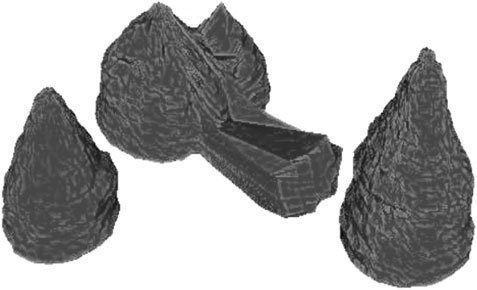
FIGURE 1. Example of multi-topology reconstructed cave in the mining area.
The detection targets inside the gas storage are mainly the walls of the gas storage and the changes in the distances between the sonar detection equipment and the walls of the gas storage. Due to the different solubility of different salt minerals in the gas storage formed by brine mining, the wall roughness of the gas storage has a great impact on the sonar detection (Wen et al., 2012).
Study on the effects of rough walls on acoustic attenuation
In this paper, the approximate three-dimensional modeling of the salt cavern was carried out using the parametric surface, and the wall surfaces of the salt cavern with different roughness were obtained. The rough surfaces of the three-dimensional model were constructed by the following double sum function:
where, x and y are the spatial coordinates; m and n are the spatial frequencies;
where, β represents the speed of high frequency attenuation, which controls the changes in the surface roughness.
When the frequency of the detected acoustic wave is high enough, on the irradiated interface of the local acoustic wave, as shown in Figure 2, the problem can be approximately regarded as a wave scattering problem with a large-scale uneven surface (Wen et al., 2012). Considering the calculation of the scattering field by Kirchhoff approximation, the concept of the effective reflection coefficient was introduced in this paper. Through the effective reflection coefficient, the walls of the salt cavern and the medium in it can form a whole, and the sound field computation model can be established by the acoustic wave transmission and reflection on the walls of the salt cavern.

FIGURE 2. Schematic diagram of sound wave incidence under non-ideal conditions.
Due to the concavo-convex surface boundaries of the salt-cavern cavities, the roughness is different at different positions. The sound field can be divided into two parts, with one being the most effective area participating in the formation of the reflected signal, where the acoustic wave will form the coherent component of the reflected signal, and the other being the incoherent component generated by the uneven surfaces of the sound field, which will form the acoustic scattering of the acoustic wave (Wen et al., 2012).
When the acoustic wave is vertically incident and received vertically, the received RMS sound pressure value can be expressed as follows (Wen et al., 2012):
where,
The maximum irradiated area of the scattering surface is determined by the directional effective half-opening angle
where,
In general, the scattering coefficient
If the effective opening angle
According to the scattering field theory:
where,
where,
When the wall surface of the salt-cavern gas storage is gently undulating, the scattering coefficient of the small-scale uneven surface can be expressed with the Kirchhoff approximation:
where,
Through Eqs 10, 11, the relationship between the effective reflection coefficient and the actual one can be obtained:
It can be seen from the above formula that, the effective reflection coefficient of the acoustic wave is related to the frequency of the acoustic wave and the root mean square of the inclination angle of the rock wall unevenness. In order to study the direct relationships between the three, the effective reflection coefficient was calculated using MATLAB. Take the sonar detector parameters currently used in Jintan, Jiangsu Province, China as an example, let the frequency of the acoustic wave be 500 KHz–4 MHz, the actual reflection coefficient 1, the root mean square of the inclination angle 0.4, 0.5, 0.6 and 0.7, the sound speed 1400 m/s, 1500 m/s, 1600 m/s and 1700 m/s, the emitted sound intensity 100 dB, and the variance of the unevenness of the rock wall 10–3. The calculation results of the effect of the effective reflection coefficient are shown in Figure 3.
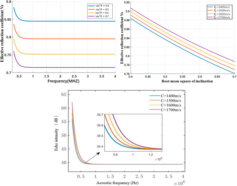
FIGURE 3. Relationship between sound frequency and echo intensity at different sound speeds.
It can be seen from Figure 3 that when the sound speed was 1400 m/s, at the acoustic wave frequency of about 500 kHz, the effective reflection coefficient decreased with the increase of frequency; at a frequency between 500 kHz and 4 MHz, the effective reflection coefficient decreased with the root mean square of the inclination angle increasing; and at a frequency above 500 kHz, the increase of the acoustic wave frequency will not affect the effective reflection coefficient, indicating that when the acoustic wave frequency increases to a certain value, the reflected energy of the acoustic wave will not be affected by the frequency. It can be seen from Figures 4, 5 that the higher the sound speed, the greater the effective reflection coefficient, and the higher the sound intensity of the acoustic echo.
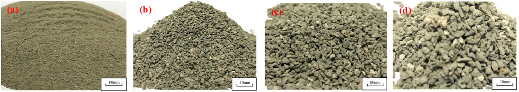
FIGURE 4. Physical images of insoluble particles in salt cavern gas storage with different diameters. (A) (<0.5 mm); (B) (0.5–1.0 mm); (C) (1.0–2.0 mm); (D) (2.0–3.0 mm).
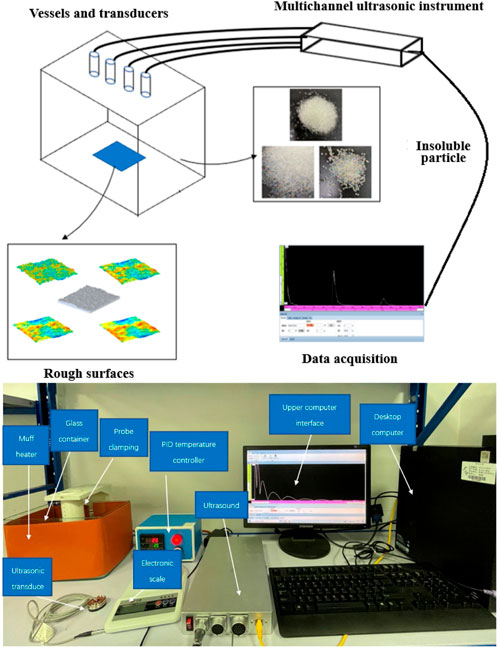
FIGURE 5. Overall experimental platform and schematic diagram.
Physical properties of insoluble particles
The cavities in salt caverns are usually built by injection of fresh water and drainage of brine. This method will dissolve the soluble salt and other media in the cavities of the salt cavern, resulting in changes in the water-solid interface of the cavity. Generally speaking, brine contains large amount of soluble salts, which change in the vertical direction of the cavities (Jiang et al., 2014). Due to the high density of brine and its flowing, the brine often contains a large amount of insoluble particles, which leads to complexity and uncertainty in the propagationof acoustic waves in the medium, so it is necessary to study how the insoluble particles affect the attenuation characteristics of the acoustic waves in the brine medium.
When the diameter of the insoluble particles is small, the particles are usually cubic or spherical. When the particle diameter increases to a certain value, the shape of the particles gradually becomes irregular, often with a honeycomb structure. The larger the particle diameter is, the more obvious the honeycomb structure and the rougher the particle surfaces will be, and the stronger the scattering of acoustic waves will be (Shi, 2015). The actual physical forms of insoluble particles in a salt-cavern gas storage are shown in Figure 4 (Li et al., 2021).
It can be seen from Table 1 that the diameters of insoluble particles are mainly concentrated between 0.25 mm and 10 mm, and the particle porosity increases with the increase of the diameter.
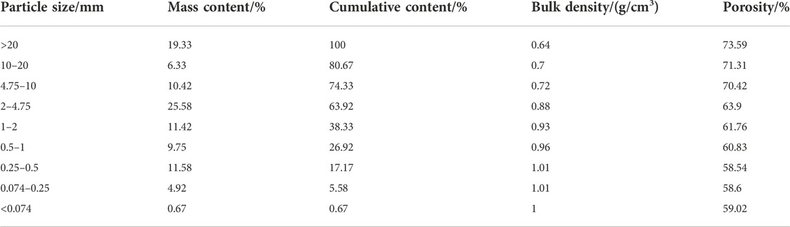
TABLE 1. Jintan insoluble particle distribution table.
In this paper, Jintan gas storage in Zhejiang was taken as the object, where the related parameters of insoluble particles were investigated and analyzed. The investigation results are shown in Table 1.
Experimental study
Experimental setup and materials
In order to simulate the propagation process of acoustic waves in the complex environment of the salt-cavern gas storage, an experimental platform was built, as shown in Figure 5, which was used to drive the ultrasonic transducer to transmit and receive acoustic waves through the ultrasonic instrument. The acoustic data were obtained through external equipment. The experimental data were recorded, and finally processed. External heating equipment and foam were used to thermally insulate the container to ensure that the experimental temperature would not change near the set value, so as to study the changes in acoustic attenuation.
The measurement of the ultrasonic attenuation coefficient was obtained by calculating the relationship between the two ultrasonic wave amplitudes and the acoustic propagation distance according to the following formula:
where,
With Eq. 2, a 3D models with 4 different rough surfaces was established in the 3D software, as shown in Figure 6, and also 3D printed, as shown in Figure 7. The size of the experimental model was 100 mm × 100 mm × 17 mm. Since the roughness of the model surfaces cannot be accurately defined, the factor
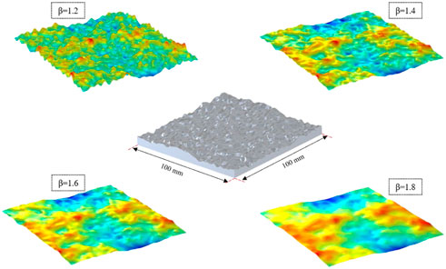
FIGURE 6. 3D models of four different rough surfaces.
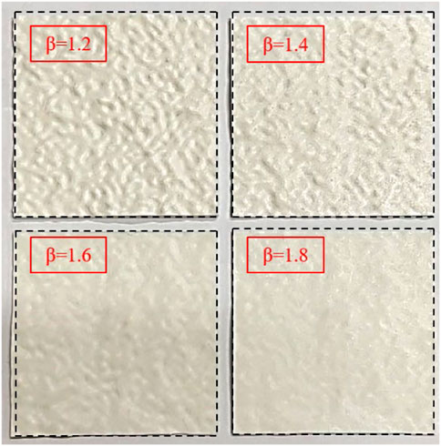
FIGURE 7. Four models of 3D printing.
As can be seen from Figures 6, 7, with
According to the survey results in Table 1 above, the diameter of the insoluble particles ranges from 0.25 mm to 10 mm. In this experiment, spherical glass beads as shown in Figure 8 were used as the insoluble particles in the salt cavern, with a diameter of 1 mm, 1.5 mm and 2 mm. The related physical parameters of glass beads are shown in Table 2. As glass beads do not dissolve, whose physical parameters are close to the insoluble particles in a salt cavern, so they can be used as the substitutes in the experiment.
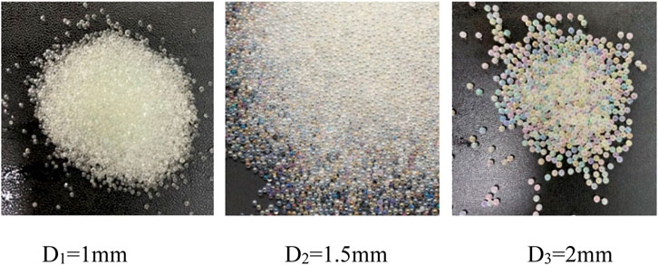
FIGURE 8. Insoluble particle diameter distribution.
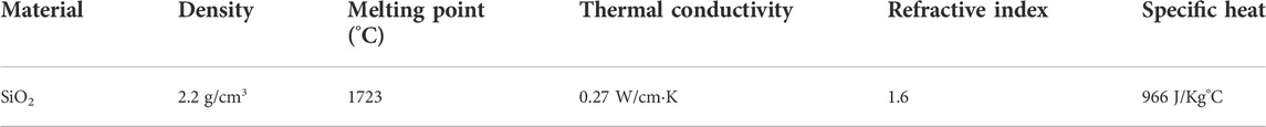
TABLE 2. Physical parameters related to glass beads.
Experimental research on wall roughness
In the experiment, pure water was used as the acoustic propagation medium, with a height of 160 mm, and the distances between the ultrasonic transducer and the reflecting walls were 145 mm, 117 mm, 127 mm, 127 mm, 129 mm, and 114 mm, respectively. The temperature of the solution was measured to be 30°C. According to the existing sold equipment parameters, the excitation voltage of the ultrasonic transducer 150 V, the sampling frequency 2 MHz, the RPF 2 KHz, and the signal gain set according to the specific conditions in the experiment. Mean filtering was performed on the received waveforms. The excitation frequencies of the ultrasonic transducer were 0.5 MHz, 1 MHz, 2 MHz, 3.1 MHz, 4 MHz and 5 MHz, and the obtained operating frequencies of the ultrasonic transducer 0.5 MHz, 1 MHz, 2 MHz, 3.1 MHz, 4 MHz and 5 MHz, respectively. The average of multiple measurements was taken, with the measurement results shown in Figure 9.
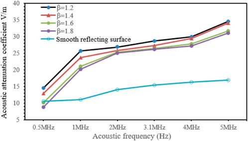
FIGURE 9. Variation of the acoustic attenuation coefficient with the roughness of the reflecting wall.
It can be seen from Figure 9 that the roughness of the reflective surface had a great effect on the acoustic attenuation coefficient, in which the acoustic frequency was the main influencing factor. As the roughness of the reflecting surface increased, the acoustic attenuation coefficient tended to increase. The acoustic attenuation coefficient of each reflecting wall differed greatly at 1 MHz, and less at 5 MHz. The experimental measurements were carried out on reflecting surfaces with different roughness using different acoustic frequencies. In the same medium environment, the acoustic attenuation coefficients measured at different acoustic frequencies were different. Specifically, the acoustic attenuation coefficient increased with the increase of the acoustic frequency, indicating that the roughness of the reflecting surface has a great impact on the acoustic attenuation coefficient.
Effect of insoluble particles on sound attenuation
Glass beads with a diameter of 0.1 mm, 0.15 mm, and 2 mm were placed in the container, and then stirred to make them evenly distributed on the bottom surface of the container. At the same time, the solution temperature was measured to make sure it was 30°C. After the solution temperature was stabilized and the glass beads evenly distributed, the experiment was carried out. The solution was sodium chloride solution with a mass fraction of 2%. In the same way, the parameters of the particles with other diameters were measured. The excitation voltage of the ultrasonic transducer was 150 V, the sampling frequency 2 MHz, and the RPF 2 KHz. The received waveforms were average filtered. The excitation frequency of the ultrasonic transducer was 0.5 MHz, 1 MHz, 2 MHz, 3.1 MHz, 4 MHz and 5 MHz, and the obtained operating frequencies of the ultrasonic transducers were 0.5 MHz, 1 MHz, 2 MHz, 3.1 MHz, 4 MHz, and 5 MHz. The heights of the ultrasonic transducers from the bottom of the containers were 145 mm, 117 mm, 127 mm, 127 mm, 129 mm, and 114 mm, respectively. The time and voltages of the echoes were measured multiple times and averaged, with the measurement results shown in Figure 10.
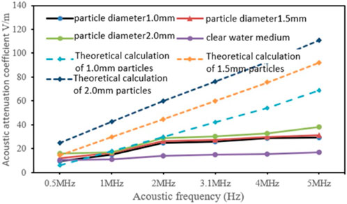
FIGURE 10. Variation of sound wave attenuation coefficient with diameter of insoluble matter.
It can be seen from Figure 10 that, after the particles were added, the acoustic attenuation coefficient increased significantly. At the same acoustic frequency, the larger the particle diameter, the stronger the acoustic scattering, and the larger the acoustic attenuation coefficient, indicating that the particle diameter has a positive correlation with the acoustic attenuation coefficient; with the same particle diameter, the higher the acoustic frequency, the greater the acoustic attenuation coefficient, indicating that the acoustic frequency and the particle diameter have obvious effects on the acoustic attenuation coefficient of the sodium chloride solution with the same concentration and temperature. When the acoustic frequency was high, the difference between the experimental result and the theoretical calculation was large. The reason is that in the acoustic attenuation experiment of insoluble particles, the particles were distributed on the bottom surface of the container because they were heavier than the solution, and accordingly, acoustic waves only came into contact with the particles at the bottom of the container and generated the scattering effect, while in the Urick model, the calculation of the scattering attenuation was carried out on the assumption that the particles were uniformly distributed in the solution, and that the acoustic waves interacted with the insoluble particles in the process of emission and reception and generated the scattering effect multiple times instead of generating it only at the bottom of the container.
Conclusion
This paper carried out theoretical analysis on the ultrasonic attenuation in the salt-cavern cavities, focusing on the effects of propagation distance, wall roughness, and insoluble particles on the acoustic attenuation, obtained the relationships between the acoustic frequency, sound speed and effective reflection coefficient, and theoretically verified the feasibility of ground simulation experiments. The main conclusions are as follows:
(1) At the same acoustic frequency, the larger the particle diameter, the stronger the acoustic scattering, and the larger the acoustic attenuation coefficient; the same particle diameter, the higher the acoustic frequency, the greater the acoustic attenuation coefficient.
(2) The roughness of the inner wall surfaces in the salt-cavern gas storage also has an effect on the acoustic attenuation. The inner wall surfaces are at the solid-liquid interface, where the acoustic impedance changes due to the change of the propagation medium; too much difference in acoustic impedance will cause serious attenuation of acoustic waves.
Data availability statement
The original contributions presented in the study are included in the article/Supplementary Material, further inquiries can be directed to the corresponding author.
Author contributions
Al authors listed have made a substantial, direct, and intellectual contribution to the work and approved it for publication.
Conflict of interest
The authors declare that the research was conducted in the absence of any commercial or financial relationships that could be construed as a potential conflict of interest.
Publisher’s note
All claims expressed in this article are solely those of the authors and do not necessarily represent those of their affiliated organizations, or those of the publisher, the editors and the reviewers. Any product that may be evaluated in this article, or claim that may be made by its manufacturer, is not guaranteed or endorsed by the publisher.
References
Chen, Z. Q., Mei, L., Wang, Y. W., Chen, L. G., and Ni, C. L. (2001). Reflection and transmission of ultrasonic waves from double rough surfaces. J. Mech. Strength (01), 98–101.
Fu, W. H., Jin, T., and Tian, X. P. (2010). A finite element model of sound propagation in regions with non-uniform temperature. J. Fudan Univ. Nat. Sci. 49 (01), 132–136.
Hutchins, D. A., Watson, R. L., Davis, L. A. J., Akanji, L., Billson, D. R., Burrascano, P., et al. (2020). Ultrasonic propagation in highly attenuating insulation materials. Sensors 20 (8), 2285. doi:10.3390/s20082285
Jiang, D. Y., Yi, L., Chen, J., Ren, S., Zhang, J. W., and Li, Y. P. (2014). Similar experiment of the concentration field in layered salt-rock cavity in construction period. J. Sichuan Univ. Eng. Sci. Ed. 05 (033), 14–21.
Li, P., Li, Y., Shi, X., Zhao, K., Liu, X., Ma, H., et al. (2021). Prediction method for calculating the porosity of insoluble sediments for salt cavern gas storage applications. Energy 221 (8), 119815. doi:10.1016/j.energy.2021.119815
Li, Y. P., Shi, X. L., Liu, W., Wang, B. W., Ma, X. Q., and Yang, C. H. (2016). Motion of insoluble subsidence during leaching sump for salt cavern storage. Chin. J. Rock Mech. Eng. 35 (01), 23–31.
Liang, W. G. (2004). Study on multi-field coupling theory and its application of hydraulic fracturing and solution mining for salt deposits. Taiyuan, China: Taiyuan University of Technology.
Liu, J. (2019). Propagation characteristics of ultrasound in non-uniform gas-solid two-phase medium. Nanjing, China: Nanjing University of Science & Technology.
Ma, X. Q., Xu, Z. J., Chen, L. P., and Shi, X. L. (2021). Creep deformation analysis of gas storage in salt caverns. Int. J. Rock Mech. Min. Sci. 139, 104635. doi:10.1016/j.ijrmms.2021.104635
Ogilvy, J. A. (1988). Computer simulation of acoustic wave scattering from rough surfaces. J.phys.d Appl.phys 21 (2), 260–277. doi:10.1088/0022-3727/21/2/006
Pfeifle, T. W., Brodsky, N. S., Munson, D. E., and Munson, D. (1998). Experimental determination of the relationship between permeability and microfracture-induced damage in bedded salt. Int. J. Rock Mech. Min. Sci. 35 (4–5), 593–594. doi:10.1016/s0148-9062(98)00058-8
Shi, L. Y. (2015). Acoustic measurements of the water column suspended particles. Hangzhou, China: Zhejiang University.
Tao, X. D. (1996). Reflection and transmission of sound wave perpendicular to the interface between two media. Mod. Phys. Knowl. (S1), 55–56.
Tsuji, K., Nakanishi, H., and Norisuye, T. (2021). Viscoelastic ECAH: Scattering analysis of spherical particles in suspension with viscoelasticity. Ultrasonics 115, 106463. doi:10.1016/j.ultras.2021.106463
Wang, J. X., and Cheng, J. H. (2020). Research on relationship between tailings slurry concentration and ultrasonic attenuation coefficient. Industrial Mine Automation 6 (2), 5.
Wang, Y., and Zhang, X. F. (2018). Acoustic radiation force of a fluid cylindrical particle in obliquely incident plane wave. J. Shaanxi Normal Univ. Sci. Ed. 46 (5), 51–55.
Wen, W., Chen, J., and Wang, Y. (2012). Research on the technology of three-dimensional surface topological reconstruction of salt caverns supported by 3D GIS[J]. Land Resour. Inf.
Wu, Z. D., Zheng, D. W., Li, D. G., and Deng, X. J. (2019). Feasibility study and suggestions on constructing underground gas storage in abandoned mines in China. Coal Econ. Res. 39 (5), 15–19.
Yu, H., Tan, C., and Dong, F. (2020). Measurement of particle concentration by multi-frequency ultrasound attenuation in liquid-solid dispersion. IEEE Trans. Ultrasonics Ferroelectr. Freq. Control 68 (99), 843–853. doi:10.1109/tuffc.2020.3020361
Zhang, B., An, G. Y., and Liu, T. H. (2021). Prediction of Salt horizon distribution for Pingding salt cavern underground gas storage. J. Salt Sci. Chem. Industry 50 (02), 5-9–13.
Zhao, J. (2019). Desulfurization operation technology of underground gas storage containing hydrogen sulfide in North China. Chem. Eng. oil gas 48 (06), 1–6.
Zhao, J., Xie, J., Sun, G. H., Song, Y. N., and Zhao, Q. (2020). Operation risks and technical countermeasures of underground gas storage containing hydrogen sulfide in north China. Storage Transp. Eng. 39 (03), 56–63.
Keywords: salt-cavern gas storage, sonar detection, acoustic attenuation, wall roughness, insoluble particles
Citation: Yang H, Wang Y, Dai Y, Zhang J and Chen G (2023) On the acoustic attenuation characteristics of sonar detection in the salt-cavern gas storage environment. Front. Earth Sci. 10:1029946. doi: 10.3389/feart.2022.1029946
Received: 28 August 2022; Accepted: 22 September 2022;
Published: 04 January 2023.
Edited by:
Hongtu Zhang, Henan Polytechnic University, ChinaReviewed by:
Feng Du, China University of Mining and Technology, Beijing, ChinaZhibo Zhang, University of Science and Technology Beijing, China
Chaojun Fan, Liaoning Technical University, China
Copyright © 2023 Yang, Wang, Dai, Zhang and Chen. This is an open-access article distributed under the terms of the Creative Commons Attribution License (CC BY). The use, distribution or reproduction in other forums is permitted, provided the original author(s) and the copyright owner(s) are credited and that the original publication in this journal is cited, in accordance with accepted academic practice. No use, distribution or reproduction is permitted which does not comply with these terms.
*Correspondence: Yu Wang, eGh3YW5neXVAeWVhaC5uZXQ=