 Dingqi Li1
 Yubo Chen
- 1Collaborative Innovation Center of Coal Work Safety and Clean High Efficiency Utilization, Henan Polytechnic University, Jiaozuo, China
- 2International Joint Research Laboratory of Henan Province for Underground Space Development and Disaster Prevention, Henan Polytechnic University, Jiaozuo, China
Efficient gas extraction technology is an important topic for low permeability and high gas outburst coal seam. Based on the engineering background of Hudi Coal Mine with the soft and hard coal seams and the existing hydraulic permeability enhancement technology, a new construction process to improve coal seam permeability was proposed to effectively reduce coal seam gas content and the risk of coal and gas outburst. In this measure, the roadway in floor was replaced with a directional main borehole, directional branch boreholes were used to replace crossing holes, and soft coal was mined along soft sub layers via the directional drilling machine and directional hydraulic jet. Main boreholes are drilled parallel to the seam in the coal seam floor, and branch boreholes are drilled through the floor and coal seam. The numerical simulation was used to study the permeability improvement effect of different mining diameters by the proposed measure. The result showed that, as the mining diameter increased from 2 m to 4 m, the average influence diameter of coal seam porosity increased from 15.44 m to 19.65 m, and the average influence diameter of the permeability increased from 15.75 m to 20.07 m, which is three times the influence range of the ordinary borehole. The application of the proposed measure and its supporting equipment was carried out under the special coal seam and gas conditions of Hudi Coal Mine. Results show that the soft coal was mined efficiently along the soft sub layer using the main borehole, branch boreholes, and directional hydraulic jet. Compared the traditional hydraulic flushing in the borehole with the ordinary drilling machine, the average speed of mining soft sub layers increased from 0.5 t/h to 3.6 t/h, the equivalent mining diameter of soft sub layers increased from 1.2 m to 7.6 m, and the average flow of gas extraction increased from 0.41 m3/d to 6.25 m3/d. The conclusions obtained in this study can provide a reference for coal mine gas extraction with similar coal seam conditions.
1 Introduction
As the depth of coal mining increases, ground stress, gas pressure and coal seam gas content continue to increase, making coal mine gas control increasingly difficult. Coal mine gas disaster is a major accident affecting the safety of coal mining (Yuan, 2021). Some coal seams in China are deep buried, tectonic stress concentration and low permeability, which lead to low gas extraction efficiency and difficulty to eliminate the danger of coal and gas outbursts. High depth of cover, concentrated tectonic stress (Lei et al., 2019), and low permeability of some coal beds in China cause low gas extraction efficiency and high difficulty in eliminating the danger of coal and gas outbursts. Many methods have been proposed to control and prevent such disasters (Wang et al., 2021).
Research has shown that stress relief in coal seams can significantly increase the permeability of coal seams (Zhang et al., 2017). In order to improve the permeability of coal seams more effectively, researchers have conducted a lot of research on different stress relief methods and rock mechanics (Wang et al., 2022; Xia et al., 2022). The effective stress relief and improvement of permeability can primarily control and prevent coal and gas outbursts in the coal seam with tectonic soft coal and thus increase the efficiency of gas drainage (Zhang et al., 2019). Protective layer exploitation can effectively reduce stress and improve permeability under the condition of multiple coal seams (Cheng et al., 2018; Jia et al., 2022; Fang et al., 2021; Fang et al., 2022; Niu et al., 2021; Ma et al., 2021). Hydraulic measures, gas fracturing, and other measures are adopted to improve the permeability of coal seams and the efficiency of gas pre-extraction in single low-permeability coal seams (Lu et al., 2017; Xue et al., 2017; Feng and Shi, 2019; Guo et al., 2019; Lu et al., 2021). Hydraulic flushing in borehole has been widely applied to realize permeability improvement and rapid elimination of coal and gas outbursts in soft coal seams with low permeability (Feng et al., 2017; Li, 2019; Chen et al., 2020; Cao et al., 2021).
However, the effect of pressure relief and permeability enhancement via traditional hydraulic punching technology has limitations, such as small stress relief range, easy formation of stress concentration and existence of gas extraction blank zone (Wang et al., 2020). In addition, the traditional hydraulic flushing method is not well for stress relief and permeability improvement of special coal seams: soft-hard composite coal seams. Therefore, a safe and efficient alternative method of self-protective layer mining was proposed (Li, 2014). In this method, directional hydraulic flushing along soft sub layers of the coal seam was implemented using directional water jets and crossing holes. The gas content of coal seam was reduced and the stress concentration gradually decreases with the creep deformation of the residual soft coals in sub layers. However, directional hydraulic flushing along soft sub layers of the coal seam is more difficult using directional water jets and crossing holes, and gas extraction is a large project with the specialized rock roadway and crossing holes, which long construction period and high cost.
Based on traditional hydraulic flushing, a new construction process to improve coal seam permeability was proposed to effectively reduce coal seam gas content and the risk of coal and gas outburst. The directional main borehole is used to replace the rock roadway in coal floor and directional branch boreholes are utilized to replace crossing holes to reduce the cost of gas extraction. At the same time, soft coal is mined along soft sub layers using the main borehole, branch boreholes, and directional hydraulic jet to relieve the stress and improve the permeability of the coal seam. By taking the special gas geological conditions of Hudi Coal Mine as an example, the evolution characteristics of porosity and permeability of coal seam before and after hydraulic mining along soft sub layers were simulated with COMSOL software. And the related equipment, processes, and effects of the proposed method were introduced and compared with the application in Hudi Coal Mine.
2 Engineering background and measures
2.1 Engineering background
The 1,305 working face of No. 3 coal seam in Hudi Coal Mine was taken as engineering background of the research for numerical simulation and field test. Hudi Coal Mine is located at Qinshui Basin in Shanxi province, China, with geographical coordinates of east longitude 112°34′06″ to 112°36′14″ and north latitude 35°42′38″ to 35°44′33″, with a field area of 5.1253 km2. The location of Hudi Coal Mine is shown in Figure 1A.
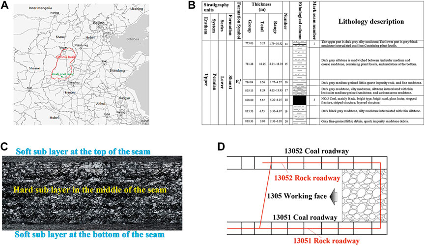
FIGURE 1. Engineering background of Hudi Coal Mine. (A) Coal mine location. (B) Column diagram of coal seam. (C) No.3 coal seam structure. (D) Test site.
The designed production capacity of Hudi Coal Mine is 60 × 104 t/a, and the No. 3 coal seam was currently mined with the risk of coal and gas outbursts. The column diagram of coal seams in Hudi Coal Mine is shown in Figure 1B. The gas content and pressure of No. 3 coal seam is 14.48–24.56 m3/t and 1.24–3.83 MPa, respectively. Due to the influence of gliding tectonics, tectonic soft coal mainly distributed in the top and bottom of No. 3 coal seam in Hudi Coal Mine, which is illustrated in Figure 1C. The average thickness of each tectonic soft sub layer is 0.3 m. The difficulty in relief of gas pressure for soft sub layers causes low efficiency in gas extraction, mining, and tunneling in the coal mine. The test site is located at the 1,305 working face and the roadway at the bottom of No. 3 coal seam of Hudi Coal Mine, which is illustrated in Figure 1D.
The gas of 1,305 working face was extracted using drilling boreholes in the coal seam for 6 months before the test. However, ordinary drilling cannot satisfy the gas extraction in low permeability coal seam, and the gas content of the coal seam was still above the standard of gas extraction, and the hazard of coal and gas outburst still exists. Therefore, it is necessary to take pressure relief and permeability enhancement measures for the coal seam in 1,305 working face.
2.2 Introduction of measure and equipment
2.2.1 Process of the measure
Based on the special engineering background of the soft hard composite coal seam, and combined with the protective layer mining and hydraulic punching technology, the new measure is proposed to mine out soft coal from soft sub layer via specific construction techniques. Different from traditional hydraulic punching technology, the directional drilling machine and hydraulic jet are used to mine soft sub layers. So as to achieve the effect of mining self-protective layers, and realize rapid stress relief and permeability improvement of the coal seam with soft sub layers. The surrounding rock stress reduces and gas desorption and permeability of the residual layer of coal seam improve rapidly after directional hydraulic mining along soft sub layers to realize the efficient regional gas extraction and risk elimination of coal and gas outbursts. Theory on permeability improvement with the directional drilling machine and hydraulic jet is shown in Figure 2A. This method has the advantages of satisfactory reliability, high efficiency, and low cost. A uniform area of pressure relief can be formed within the entire mining range of the coal seam in a short time after directional hydraulic mining and the creep of the residual soft coal in soft sub layers to solve the stress concentration phenomenon caused by hydraulic measures, such as hydraulic punching and fracturing.
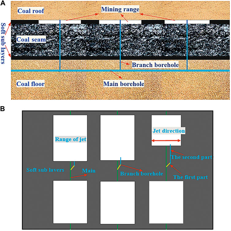
FIGURE 2. Permeability improvement by directional drilling machine and hydraulic jet. (A) Profile for permeability improvement by directional drilling machine and hydraulic jet. (B) Plan for permeability improvement by directional drilling machine and hydraulic jet.
Main boreholes are constructed parallel to the seam in the coal seam floor, and branch boreholes are drilled in the floor and coal seam. The branch borehole consists of two parts, namely, the crossing hole and the soft sub layer parallel to the seam. Both main and branch boreholes are constructed using a high-power directional drilling machine. The directional hydraulic jet is used for hydraulic mining during the process of retracting drill pipes in the second part of branch boreholes. Figure 2B shows the layout of directional hydraulic mining with the high-power directional drilling machine along the soft sub layer.
2.2.2 Technical equipment
As shown in Figure 3A, the equipment used in the test of mining soft sub layers in Hudi Coal Mine mainly includes the ordinary drilling machine, directional drilling machine, high-pressure water pump, high-pressure sealing rotary device, high-pressure pipes, high-pressure valves, high-pressure sealing drill pipes, directional jet device along soft sub layers, and gas-water separation device.
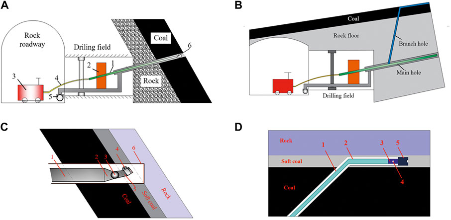
FIGURE 3. Equipment and device used in the test. (A) Equipment for directional jet with ordinary drilling machine. (B) Equipment for directional jet with ordinary drilling machine. (C) Device for directional jet with ordinary drilling machine. (D) Device for directional jet with directional drilling machine.
The directional jet with the ordinary drilling machine is mainly composed of plug-type sealed steel tubes, reducer union, universal joint, and hydraulic spin sprinkler with jet torque, as shown in Figure 3B. The angle between universal joint and nozzle is adjusted according to the angle between the crossing borehole and the coal seam before mining soft sub layers to ensure that the jet direction of the nozzle is nearly parallel to the coal seam. The ordinary drilling machine is used to send the device for directional jet into the soft sub layer of the coal seam, and the direction of the hydraulic spin sprinkler with jet torque is adjusted according to the azimuth calibrated in plug-type sealed steel tubes to ensure that the direction of the rotating jet is nearly parallel to the coal seam, as shown in Figure 3C.
Two directional nozzles are fixed on both sides of the transfer joint for high and low water pressure and the transfer joint for high and low water pressure is connected between the directional drill and directional drilling pipe, as shown in Figure 3D. The pressure of water in the directional drilling pipe is increased, the water channel at the front of the transfer joint is closed, directional nozzles are opened, and the soft coal is mined by jets, which are produced by directional nozzles and parallel to the soft sub layer of the coal seam when the branch borehole in the soft sub layer is completed.
ZDY4200LPS(A) is the ordinary drilling machine used for directional hydraulic mining along the soft sub layer of the coal seam. The high-power directional drilling machine ZYL15000D is also used in the 1.5 km-long borehole to improve the efficiency of directional hydraulic mining along the soft sub layer of the coal seam. High-pressure water pumps BRW 200/31.5 and BRW 400/31.5 used in the test were fitted with caterpillars to allow self-mobility. The rated flow of pumps is 200 and 400 L/min and their rated pressure is 31.5 MPa.
3 Theoretical and numerical simulation
3.1 Mathematical evolution model
3.1.1 The mathematical model for porosity of coal
In order to establish the numerical model of flow-solid coupling theory, the following assumptions are made:
(1) The coal seam is assumed to be homogeneous and that the physical properties of all parts in the coal seam model are the same and do not change with position.
(2) The gas-bearing coal is assumed to be an isotropic linear elastic medium, and the deformation of the coal obeys the generalized Hooke’s law.
(3) The temperature of the coal seam is always constant.
(4) The gas in the coal seam is only in two states, free and adsorbed, and the adsorbed coal obeys the Langmuir equation.
(5) The gas contained in the coal seam can be regarded as an ideal gas and obeys the ideal-gas equation.
According to the definition of porosity (Ding et al., 2021):
where, φ is the porosity of coal, φ0 is the initial porosity of coal, Vp is the pore volume of coal, Vp0 is the initial pore volume of coal, ΔVp is the increment of pore volume of coal, Vb is the total apparent volume of coal, Vb0 is the initial total apparent volume of coal, ΔVb is the increment of total apparent volume of coal, Vs is the skeleton volume of coal, Vs0 is the initial skeleton volume of coal, ΔVs is the increment of skeleton volume of coal, e is the volumetric strain of coal, Vp= Vb-Vs.
ΔVs is composed of three parts: ΔVsp, the volume increment caused by the change of pore gas pressure; ΔVsf, the volume increment caused by the expansion of gas adsorbed by coal particles; ΔVst the volume increment caused by the thermoelastic expansion. The volume strain of coal skeleton can be written as
where
Assuming the temperature of the coal seam is constant, so the value for
In Eq. 3,
By combining Eqs. 3, 4, 5, the total strain of coal particle’s own deformation volume can be written as
ξp is the expansion strain of unit volume of coal after gas adsorption
where, T is the temperature of coal seam, a and b are the adsorption constant of coal, R is the universal gas constant, ρ is the density of coal, Vm is the molar volume of gas, Ks is the bulk modulus of coal skeleton.
Substituting Eqs 6, 7 into Eq. 1, the mathematical model of dynamic evolution of porosity can be obtained as follow (Tao et al., 2010):
3.1.2 Mathematical model for permeability of coal
The mathematical relationship between porosity and permeability is established by the Kozeny-Carman equation as follow (Guo et al., 2012):
In Eq. 9,
where, k is the permeability, kZ is the dimensionless constant, Sp is the unit surface area of pore volume, and AS is the total surface area of coal pores.
The permeability in the initial state is
In Eq. 11,
By the definition of porosity, the porosity can be obtained as
The new pore surface area is obtained as
where, ∂ is the increase coefficient of coal pore surface area.
By combining Eqs. 9, 10, 11, the ratio of the new permeability to the original permeability is obtained as
During the stress and strain of coal, the total surface area of coal particle per unit volume can be regarded as unchanged and ignored, so ∂≈0. Then Eq. 15 can be simplified as
In Eq. 16,
By combining Eqs. 6, 7, 15, 17, the mathematical model for permeability of coal containing gas is obtained as
3.2 Numerical simulation analysis
3.2.1 Geometric model
In order to analyze the effect of different punching positions and punching sizes on the porosity and permeability of coal seam, the COMSOL software was used to simulate the porosity and permeability after directional mining of soft sub layers. The geometric model of simulation was built according to the geological conditions of 1,305 working face in Hudi Coal Mine. The average thickness of No. 3 coal seam is approximately 5.7 m at the 1,305 working face. Stable soft sub layers with a thickness of 0.3 m can be found at the top and bottom of No.3 coal seam. The roof and floor of the coal seam are composed of mudstone and sandstone. The length, width, and height of the calculation model in the simulation were set to 25, 25, and 49.6 m, respectively, to avoid the influence of boundary effect. The height of the roof and floor is 22 m. The length of the crossing hole in the model is 24.6 m, and the mining diameter in soft sub layers is set to 2, 2.5, 3, 3.5, and 4 m. The geometric model of the numerical simulation is illustrated in Figure 4A.
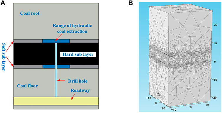
FIGURE 4. The computational model. (A) Geometric model of numerical simulation. (B) Mesh generation of geometric model.
In order to speed up the calculation process, the “extremely coarse” unit size of the model roof and floor in the software and the “finer” unit size of the coal seam in the software were used for meshing grids. The numerical model network partition is shown in Figure 4B. The experimental procedure was transient, the study step length was 1 day, and the numerical simulation ran for 180 days.
3.2.2 Parameters of numerical simulation
These parameters of the numerical simulation include density, Poisson’s ratio, initial porosity, and initial permeability of coal as well as adsorption constants, gas dynamic viscosity coefficient, coal moisture, and coal ash. Specific physical parameters are listed in Table 1.
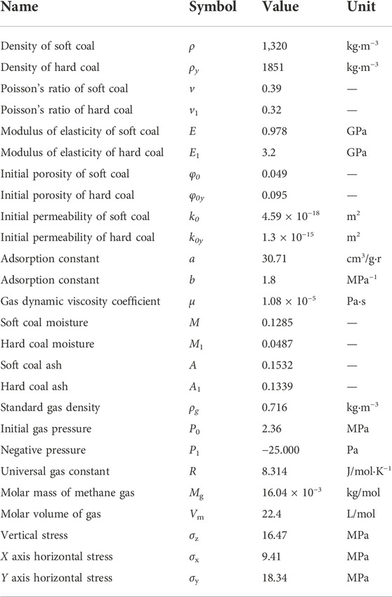
TABLE 1. Physical parameters of gas-bearing coal.
3.2.3 Numerical results analysis
In order to simulate the evolution characteristics of porosity and permeability in coal seams after directional hydraulic mining along soft sub layers, the mathematical model of coal porosity and coal permeability are input into the corresponding setting module of COMSOL multi-physics simulation. The corresponding setting module is shown in Figure 5.
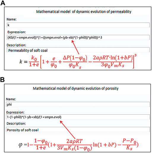
FIGURE 5. (A) Corresponding setting module for permeability of coal containing gas. (B) Corresponding setting module for porosity of coal containing gas.
The results of numerical simulation are shown in Figure 6. The gas extraction time is 180 days, the borehole diameter is 0.095 m, and the diameter of hydraulic mining in the soft sub layer at the bottom and top of the coal seam is 2.0, 2.5, 3.0, 3.5, and 4.0 m. The porosity and permeability of coal seams improve significantly after hydraulic mining in the soft sub layer and increase with the increase of the diameter of hydraulic mining in the soft sub layer.
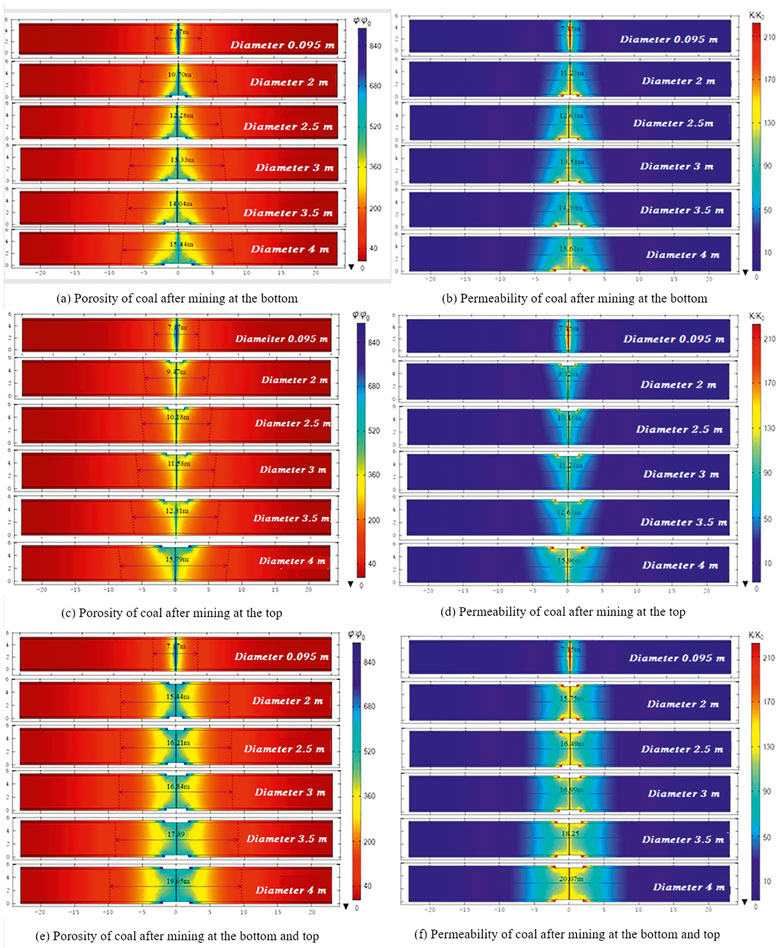
FIGURE 6. Porosity and permeability of coal seams.
The numerical simulation was conducted to analyze the improvement of the porosity and permeability after hydraulic mining in the soft sub layer. The range of porosity increasing to 40 times of initial porosity is defined as the influence diameter of porosity, and the range of permeability increased to 10 times of initial permeability is defined as the influence diameter of permeability. The average influence diameter of porosity and permeability of the crossing hole without hydraulic flushing in the soft sub layer are 7.17 and 7.15 m, respectively. The average influence diameter of porosity and permeability of hydraulic flushing in the soft sub layer at the bottom of the coal seam is 15.44 and 15.61 m, at the top bottom of coal seam are 15.79 and 15.96 m, and at the top and bottom of the coal seam are respectively 19.65 and 20.07 m, respectively, when the diameter of hydraulic flushing in the soft sub layer is 4 m. The influence diameter of porosity and permeability are larger after hydraulic flushing at the bottom and top soft sub layers.
4 Field tests
4.1 Test scheme
According to the results of numerical simulation, two soft sub layers were mining as the self-protective seam in the directional hydraulic mining scheme of No. 3 coal seam in Hudi Coal Mine. The thickness of each soft sub layer is 0.5 m, and the hardness coefficient of the soft sub layer is 0.1–0.2. The spacing of boreholes is set to 5–10 m for the comparison of gas extraction data. The pressure and flow of water jet are set to 10–28 MPa and 70–280 L/min, respectively.
As shown in Figure 7, the test site was divided into three zones, A, B, and C. Directional hydraulic mining with the common drilling machine was tested in zone A, and the spacing of boreholes was set to 7 m. Conventional hydraulic flushing in boreholes was tested in zone B, and the spacing of boreholes was set to 5 m. Directional hydraulic mining with the directional drilling machine was tested in zone C, and the spacing of boreholes was set to 5–10 m. Gas extraction data from conventional hydraulic flushing in boreholes, directional hydraulic mining with a common drilling machine and directional hydraulic mining with a directional drilling machine were compared and analyzed.
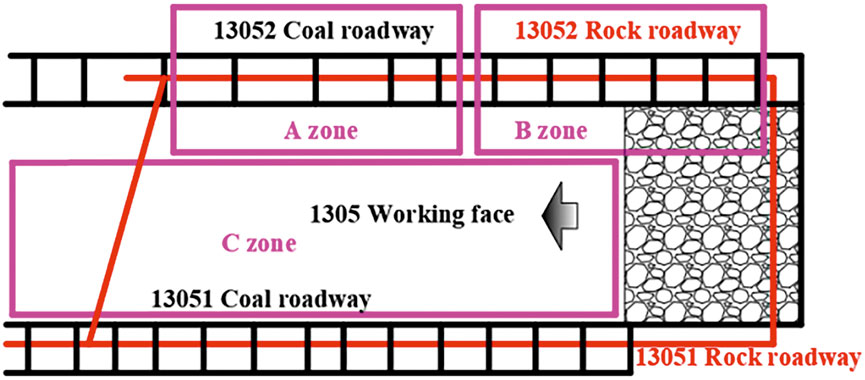
FIGURE 7. Test zone.
4.1.1 Test with the common drilling machine
Test with the common drilling machine in zones A and B of the 1,305 working face and rock roadway began on 1 August 2018. The jet pressure and flow rate of the test were set to10-28 MPa and 70–180 L/min, respectively. As shown in Figure 8A, boreholes are symmetrically arranged in the 1,305 working face and rock roadway.
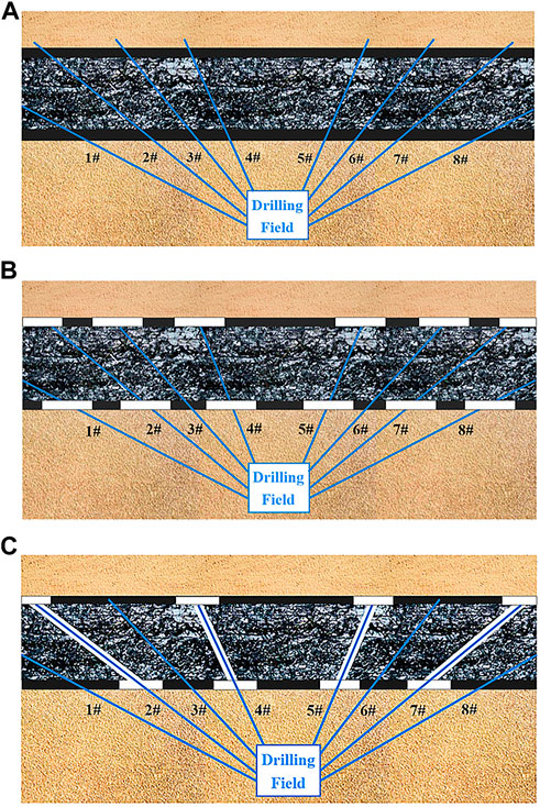
FIGURE 8. Test in zone A and B. (A) arrangement of crossing boreholes. (B) test in zone A. (C) test in zone B.
Directional hydraulic mining in zone A is only carried out in soft sub layers, and the direction of water jet is parallel to soft sub layers. The range of directional hydraulic mining is presented in Figure 8B. The upper soft layer was mined in #3 and #6 boreholes, and both soft layers were mined in #1, #2, #4, #5, #7, and #8 boreholes. Zone A has 100 groups of crossing boreholes, parallel spacing between groups is 7 m, and the average distance between crossing boreholes in the coal seam is 7 m. The device for the directional jet was sent to soft sub layers, and directional mining along the soft sub layer was carried out after retracting drill pipes.
The residual soft coal in soft sub layers appeared to creep under the action of concentrated stress, the thickness of the residual soft coal reduced, the hard sub layer of the coal seam expanded and thickened, the stress reduced, and cracks increased after directional hydraulic mining in Zone A.
The traditional hydraulic flushing was carried out in every other ordinary borehole in the coal seam of zone B. The scope of traditional hydraulic flushing in boreholes with the common drilling machine in zone B is shown in Figure 8C. The water jet perpendicular to the crossing hole was used for hydraulic flushing in #2, #4, #5, and #7 boreholes. There are 100 groups of crossing boreholes in zone B. The parallel spacing between groups is 5 m, and the average distance between crossing boreholes in the coal seam is 5 m. And the traditional hydraulic flushing was carried out in the process of drill pipe retreating.
4.1.2 Test with the directional drilling machine
The test with directional drilling machine in zone C of 1,305 working face began on 12 May 2019. The jet pressure and flow rate were set to 10-28 MPa and 120–380 L/min, respectively. Main boreholes were constructed in the rock under the coal seam, and crossing holes were manufactured as branch boreholes using the high-power directional drilling machine. The main borehole is spaced 10 m apart, and the branch borehole is 5–10 m in length along the soft sub layer. The arrangement of boreholes in directional hydraulic mining in zone C is illustrated in Figure 9A. Directional mining was carried out in branch boreholes along the soft sub layer while retracting drill pipes. The residual soft coal in soft sub layers is shown in Figure 9B. The residual soft coal crept and thinned, the pressure of the hard sub layer was relieved, and permeability increased after directional mining in the soft sub layer, as shown in Figure 9C.
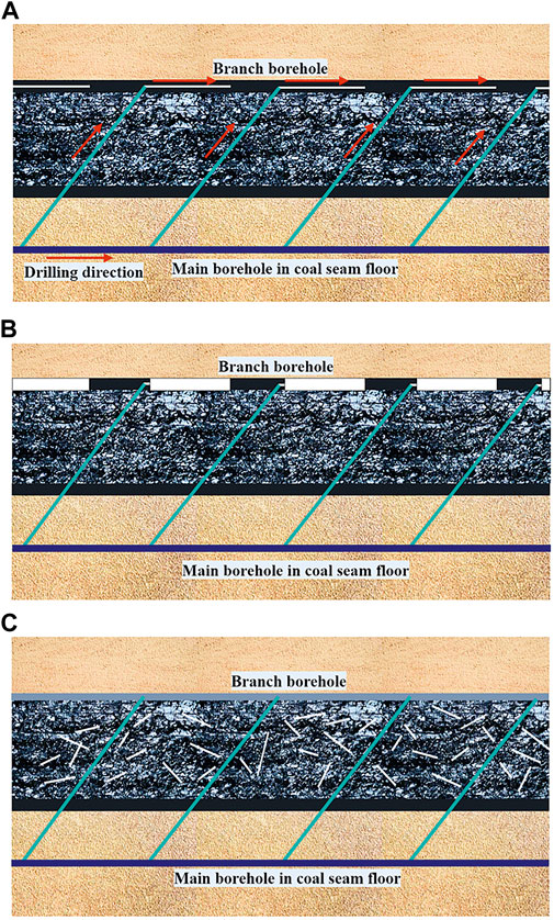
FIGURE 9. Test in zone C. (A) Boreholes of directional hydraulic mining; (B) Scope of directional hydraulic mining; (C) Effect of pressure relief and permeability improvement.
4.2 Test results
The test data for 3 months in zones A, B, and C are listed in Table 2. The comparison showed that the efficiency of hydraulic punching in the borehole with the ordinary drilling machine is very low and that of directional hydraulic mining along soft layers is high, especially in the directional hydraulic mining of the coal seam with soft sub layers using the directional drilling machine. The average speed of mining soft sub layers reached 3.6 t/h, which is 7.2 times that of conventional hydraulic punching in the borehole with the ordinary drilling machine.
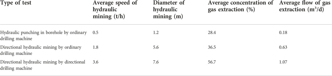
TABLE 2. Test data.
The concentration and flow of gas extraction of directional hydraulic mining with the directional drilling machine are higher, the average concentration is 56.7%, and the average flow is 6.25 m3/d. By comparison, the concentration and flow of gas extraction of conventional hydraulic punching in the borehole with the ordinary drilling machine are lower, the average concentration is 28.4%, and the average flow is 0.41 m3/d.
The excavation speed of the 13,052 coal roadway is used for comparative analysis to investigate the effect of directional hydraulic mining of the soft sub layer, as shown in Figure 10. The long square blue column represents the excavation speed after conventional extraction for 180 days without any hydraulic measures. The long square green column represents the excavation speed after conventional extraction for 90 days with conventional hydraulic punching in the borehole using the ordinary drilling machine. The long square tawny column represents the excavation speed after the special extraction for 30 days with directional hydraulic mining in the borehole with the ordinary drilling machine. Figure 10 presents that directional hydraulic mining improves the excavation speed of the coal roadway. The residual soft coal crept and the stress of the coal seam reduced evenly in the working face of the 13,052 coal roadway after 30 days of directional hydraulic mining in the soft sub layer, thereby causing even gas desorption and permeability improvement. Hence, the uniform and efficient extraction of gas in the 13,052 coal roadway significantly reduced the time of gas extraction and improved the excavation speed.
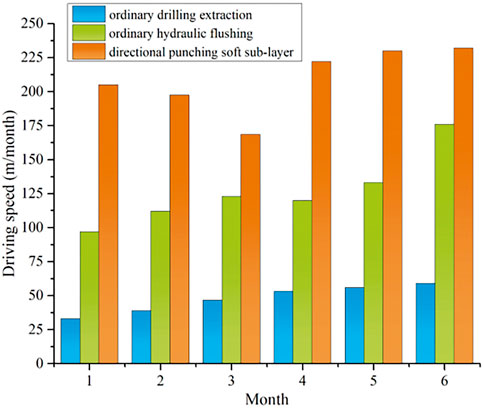
FIGURE 10. Excavation speed of coal 13,052 roadway.
Based on the gas extraction data of ordinary borehole in 1,305 working face, the effect of pressure relief and permeability enhancement of the measures proposed in this paper is compared and analyzed. In addition, the gas extraction data of 13,052 coal roadway was used for comparative analysis to investigate the effect of directional hydraulic mining of the soft sub layer, as shown in Figure 11. The black square, red ball, and blue triangle represent the average flow of gas extraction for a single borehole without any hydraulic measures, with traditional hydraulic flushing in the borehole, and with directional hydraulic mining in soft sub layers, respectively. Figure 11 shows that directional hydraulic mining significantly improves the average flow of gas extraction. Compared with that of hydraulic punching in the borehole, the average flow of gas extraction increased from 0.41 m3/d to 6.25 m3/d with directional hydraulic mining in soft sub layers. According to the verification of the actual coal roadway excavation in Hudi Coal Mine, the regional drainage standard is achieved in 30 days after the completion of directional hydraulic mining. Hence, the risk of coal and gas outbursts is effectively eliminated and the safety requirements of coal roadway driving are met.
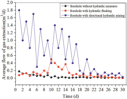
FIGURE 11. Comparative analysis of gas extraction data.
4.3 Analysis of influencing factors
The test result from zones A and C were used to analyze the influence of creep time, water jet parameters, and width of residual soft coal on pressure relief and gas drainage of the coal seam.
4.3.1 Influence of creep time on pressure relief
The permeability of the coal seam before and after directional hydraulic mining was measured in test area A to discuss the influence of directional hydraulic mining in soft layers on pressure relief and permeability improvement of the coal seam. The average initial permeability of the coal seam in the experimental area is 25 m2/(MPa2·d), which increased to 408 m2/(MPa2·d) after 30 days of directional hydraulic mining. Analysis of the coal seam exposed by the working face demonstrated that boreholes are absent in soft sub layers, the thickness of soft sub layers significantly reduce during tunneling in zones A and C, and a portion of boreholes in soft sub layers is filled during tunneling in zone B, and the change in thickness of soft sub layers is non-significant after 90 days of directional hydraulic mining in the 1,305 working face. The residual pillar is relatively wide and the creep deformation and stress relief are unclear after conventional hydraulic punching in the borehole with the ordinary drilling machine in zone B.
The average thickness of the residual soft coal with different creep times was measured after directional hydraulic mining during the process of working face mining in zone C to verify the influence of time on the creep of soft coal and the stress relief of the coal seam. The equivalent width of the residual soft coal is 2.4 m, the average initial thickness is 0.52 m, and the final average thickness is 0.22 m after 90 days of directional hydraulic mining, as shown in Figure 12A. The average thickness of the residual soft coal significantly reduced after 20 days of directional hydraulic mining of soft coal; hence, the stress of the coal seam will reduce rapidly in 20 days. The creep of the residual soft coal between boreholes in the soft sub layer increased, the soft coal thinned, and the permeability of the coal seam further increased with the increase of time.
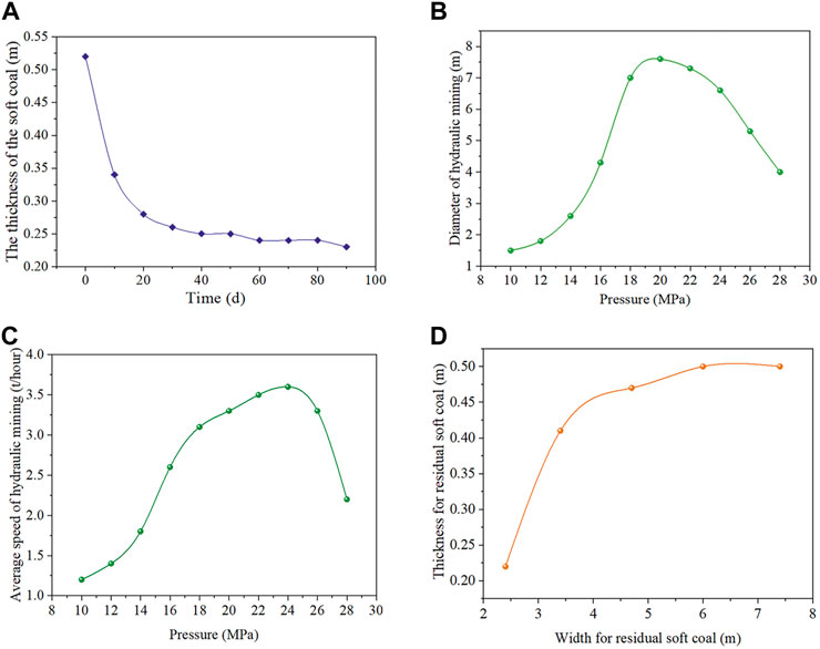
FIGURE 12. Influence of residual soft coal and jet on the test. (A) Thickness of residual soft coal with different creep time. (B) Influence of jet pressure rate on efficiency of directional hydraulic mining. (C) Influence of flow rate on efficiency of directional hydraulic mining. (D) Influence of residual soft coal width on thickness of residual soft coal.
4.3.2 Influence of jet on the efficiency of directional hydraulic mining
The effects of jet pressure and flow rate on directional hydraulic mining efficiency were analyzed by different jet pressure (10–28 MPa) with the high-pressure water pump BRW four in zone C. This high-pressure pump is variable, and the effective flow rate of output decreases with the increase of pressure. As shown in Figures 12B,C, the efficiency of directional hydraulic mining first increases with the increase of jet pressure and decrease of flow rate and then reaches the optimal efficiency at 20 MPa. The effective range of the jet begins to decrease when the jet flow is insufficient, and the efficiency of directional hydraulic mining decreases with the increase of pressure.
4.3.3 Influence of residual soft coal width on stress relief
As different jet pressure and boreholes spacing would form the residual soft coal with different width. The spacing of drilling holes is 10 m, the jet pressure is 10–28 MPa, the equivalent diameter of the residual soft coal is 1.5–7.6 m, and the equivalent width of the residual soft coal is 2.4–8.5 m for directional hydraulic mining in zone C. The residual soft coal with different equivalent widths is used to verify its influence on the stress relief of the coal seam, as shown in Figure 12D. The large width of the residual soft coal increases its average thickness under the condition of the same time. Therefore, the width of the residual soft coal should be appropriately reduced to improve the relief effect of the coal seam.
5 Conclusion
In order to effectively solve the problem of gas control in Hudi Coal Mine and the existence of special coal seams with soft and hard composite coal seams. A new measure, which can effectively improve the permeability of coal seam, was proposed based on traditional hydraulic flushing. The effect of pressure relief and permeability improvement of directional hydraulic mining is studied by numerical simulation and field tests. The following conclusions were obtained from this study:
The numerical simulation results showed that the porosity and permeability of coal seams significantly improve after hydraulic mining in soft sub layers. In addition, the porosity and permeability increase with the increased diameter of hydraulic mining in soft sub layers. The average influence diameter of porosity and permeability for hydraulic mining in soft sub layers at the top and bottom of the coal seam was 19.65 and 20.07 m, while the diameter of mining soft sub layers at the top and bottom of the coal seam was 4 m.
The directional hydraulic mining and associated technical equipment were applied in Hudi Coal Mine. The field test results showed that the soft coal in soft sub layers was mined out effectively by the directional drilling machine, the directional hydraulic jet, main boreholes, and branch boreholes under the proposed measure. The stress was relieved and the permeability was increased in the coal seam after mining out the soft coal from soft sub layers. The directional main borehole can be used to replace the rock roadway in the coal floor and directional branch boreholes can be utilized to replace crossing holes to reduce the cost of gas extraction.
Compared with hydraulic punching with the ordinary drilling machine, the permeability of coal seam, gas extraction efficiency, and excavation speed of the coal roadway were significantly improved. The average speed of mining soft sub layers increased from 0.5 to 3.6 t/h, the equivalent diameter of mining soft sub layers increased from 1.2 to 7.6 m, the average flow of gas extraction increased from 0.41 to 6.25 m3/d, and the excavation speed of the coal roadway increased from 123 to 211 m/month by the proposed measure.
The effect of stress relief and permeability improvement is related to the creep time of residual soft coal, the width of residual soft coal, and the pressure of directional jet in Hudi Coal Mine. The effect of stress relief increased with the increase of creep time of the residual soft coal and decreased with the increase of the width of residual soft coal. In addition, the moderate pressure of the directional jet enhanced the efficiency of stress relief. The conclusions obtained in this study can provide a reference for coal mine gas extraction with similar coal seam conditions.
Data availability statement
The original contributions presented in the study are included in the article/supplementary material, further inquiries can be directed to the corresponding author.
Author contributions
YC: Writting-original draft; software; JZ: Methodology and formal analysis; DL: Supervision and conceptualization; Writing-review and editing; MW: Investigation.
Funding
This work was financially supported by the National Natural Science Foundation of China (51404094), and the Fundamental Research Funds for the Universities of Henan Province (NSFRF200202), China.
Acknowledgments
The authors also acknowledge the field data was provided by Hudi Coal Mine of Shanxi Province, China.
Conflict of interest
The authors declare that the research was conducted in the absence of any commercial or financial relationships that could be construed as a potential conflict of interest.
Publisher’s note
All claims expressed in this article are solely those of the authors and do not necessarily represent those of their affiliated organizations, or those of the publisher, the editors and the reviewers. Any product that may be evaluated in this article, or claim that may be made by its manufacturer, is not guaranteed or endorsed by the publisher.
References
Cao, Z. Y., Wang, E. Y., He, X. Q., Wang, H., Liu, Q. L., Zhang, G. H., et al. (2021). Effectiveness of pressure relief and gas drainage of hydraulic punching in short-distance coal seam group with the risk of outburst. J. Min. Saf. Eng. 38, 634–642. doi:10.13545/j.cnki.jmse.2020.0206
Chen, D. D., He, W. R., Xie, S. R., He, F. L., Zhang, Q., and Qin, B. B. (2020). Increased permeability and coal and gas outburst prevention using hydraulic flushing technology with cross-seam borehole. J. Nat. Gas. Sci. Eng. 73, 103067. doi:10.1016/j.jngse.2019.103067
Cheng, X., Zhao, G. M., Li, Y. M., Meng, X. R., Dong, C. L., and Xu, W. S. (2018). Study on relief-pressure antireflective effect and gas extraction technology for mining soft rock protective seam. J. Min. Saf. Eng. 35, 1045–1053. doi:10.13545/j.cnki.jmse.2018.05.023
Ding, X., Xiao, X. C., Wu, D., Lyu, X. F., Pan, Y. S., and Bai, R. X. (2021). Study on mechanical constitutive relationship and damage evolution of gas-bearing coal based on initial pore-cracks. Mater. Rep. 35, 18096–18103. doi:10.11896/cldb.20080083
Fang, S. H., Zhu, H. Q., Huo, Y. J., Zhang, Y. L., Wang, H. R., Li, F., et al. (2021). The pressure relief protection effect of different strip widths, dip angles and pillar widths of an underside protective seam. Plos One 16, e0246199. doi:10.1371/journal.pone.0246199
Fang, S. J., Liang, B., Sun, W. J., Shi, Z. S., Hao, J. F., Wang, B. F., et al. (2022). Study on stress evolution law of overburden under repeated mining in long-distance double upper protective layer. Energies (Basel). 15, 4459. doi:10.3390/en15124459
Feng, A. X., and Shi, W. B. (2019). Permeability increasing mechanism of hydraulic repeated fracturing in crossing-hole drilling. Coal Eng. 51, 87–90. doi:10.11799/ce201909020
Feng, D. X, J., Tao, Y. Q., Peng, S. J., Wu, X. F., and Zhang, X. M. (2017). Development of hydraulic punching test system and its application. J. Min. Saf. Eng. 7, 782–788. doi:10.13545/j.cnki.jmse.2017.04.025
Guo, P., Cao, S. G., Zhang, Z. G., Li, Y., Liu, Y. B., and Li, Y. (2012). Analysis of solid-gas coupling model and simulation of coal containing gas. J. China Coal. Soc. 37, 330–335. doi:10.13225/j.cnki.jccs.2012.s2.038
Guo, T. K., Gong, F. C., Shen, L., Qu, Z. Q., Qi, N., and Wang, T. (2019). Multi-fractured stimulation technique of hydraulic fracturing assisted by radial slim holes. J. Pet. Sci. Eng. 174, 572–583. doi:10.1016/j.petrol.2018.11.064
Jia, H. Y., Wang, K., Xu, C., and Fu, Q. (2022). Permeability distribution characteristics of underlying coal seam disturbed by mining activity. Energy Sources Part A Recovery Util. Environ. Eff. 44, 5032–5047. doi:10.1080/15567036.2019.1657207
Lei, C. K., Deng, J., Cao, K., Xiao, Y., Ma, L., Wang, W. F., et al. (2019). A comparison of random forest and support vector machine approaches to predict coal spontaneous combustion in gob. Fuel 239, 297–311. doi:10.1016/j.fuel.2018.11.006
Li, D. Q. (2019). Hydraulic drill hole reaming technology with large flow and draining of coal mine gas. Int. J. Min. Sci. Technol. 29, 925–932. doi:10.1016/j.ijmst.2018.06.003
Li, D. Q. (2014). Underground hydraulic mining of thin sub-layer as protective coal seam in coal mines. Int. J. Rock Mech. Min. Sci. (1997). 67, 145–154. doi:10.1016/j.ijrmms.2014.01.014
Lu, Y. Y., Ge, Z. L., Yang, F., Xia, B. W., and Tang, J. R. (2017). Progress on the hydraulic measures for grid slotting and fracking to enhance coal seam permeability. Int. J. Min. Sci. Technol. 27, 867–871. doi:10.1016/j.ijmst.2017.07.011
Lu, Y. Y., Li, R., Xian, X. F., Ge, Z. L., and Xia, B. W. (2021). Discussion on efficient development of deep coalbed methane by surface directional well + hydraulic slotting. J. China Coal. Soc. 46, 876–884. doi:10.13225/j.cnki.jccs.yt21.0089
Ma, J. H., Hou, C., and Hou, J. T. (2021). Numerical and similarity simulation study on the protection effect of composite protective layer mining with gently inclined thick coal seam. Shock Vib. 2021, 1–15. doi:10.1155/2021/6679199
Niu, X. G., Shi, B. M., Zhang, Z. G., and Zhang, Y. J. (2021). Stress distribution and gas concentration Evolution during protective coal seam mining. Adv. Civ. Eng. 2021, 1–12. doi:10.1155/2021/6644142
Tao, Y. Q., Xu, J., Peng, S. J., and Yuan, M. (2010). Experimental study of influencing factor of porosity and effective stress of gas-filled coal. Rock Soil Mech. 31, 3417–3422. doi:10.16285/j.rsm.2010.11.006
Wang, E. Y., Wang, H., Liu, X. F., Shen, R. X., and Zhang, C. L. (2020). Spatio temporal evolution of geostress and gas field around hydraulic punching borehole in coal seam. Coal. Sci. Techno. 48, 39–45. doi:10.13199/j.cnki.cst.2020.01.005
Wang, E. Y., Zhang, G. R., Zhang, C. L., and Li, Z. H. (2022). Research progress and prospect on theory and technology for coal and gas outburst control and protection in China. J. China. Coal Soc. 47, 297–322. doi:10.13225/j.cnki.jccs.yg21.1846
Wang, H., Wang, E. Y., Li, Z. G., Shen, R. X., and Liu, X. F. (2021). Study and application of a new gas pressure inversion model in coal seam while drilling based on directional drilling technology. Fuel 306, 121679. doi:10.1016/j.fuel.2021.121679
Xia, K. Z., Chen, C. X., Wang, T. L., Zheng, Y., and Wang, Y. (2022). Estimating the geological strength index and disturbance factor in the Hoek–Brown criterion using the acoustic wave velocity in the rock mass. Eng. Geol. 306, 106745. doi:10.1016/j.enggeo.2022.106745
Xue, Y., Gao, F., Gao, Y. N., Liang, X., Zhang, Z. Z., and Xing, Y. (2017). Thermo-hydro-mechanical coupled mathematical model for controlling the pre-mining coal seam gas extraction with slotted boreholes. Int. J. Min. Sci. Technol. 27, 473–479. doi:10.1016/j.ijmst.2017.03.012
Yuan, L. (2021). Research progress of mining response and disaster prevention and control in deep coal mines. J. China. Coal. Soc. 46, 716–725. doi:10.13225/j.cnki.jccs
Zhang, Q. G., Fan, X. Y., Liang, Y. C., Li, M. H., Li, G. Z., Ma, T. S., et al. (2017). Mechanical behavior and permeability evolution of reconstituted coal samples under various unloading confining pressures-implications for wellbore stability analysis. Energies (Basel). 10, 292. doi:10.3390/en10030292
Keywords: coal mine, directional drilling, directional jet, permeability, stress relief
Citation: Li D, Chen Y, Zhang J and Wang M (2023) Research and application of pressure relief and permeability improvement in high gas outburst mines by directional drilling and hydraulic jet. Front. Earth Sci. 10:1029429. doi: 10.3389/feart.2022.1029429
Received: 27 August 2022; Accepted: 28 October 2022;
Published: 11 January 2023.
Edited by:
Tianshou Ma, Southwest Petroleum University, ChinaReviewed by:
Qiangui Zhang, Southwest Petroleum University, ChinaKaizong Xia, Institute of Rock and Soil Mechanics, (CAS), China
Copyright © 2023 Li, Chen, Zhang and Wang. This is an open-access article distributed under the terms of the Creative Commons Attribution License (CC BY). The use, distribution or reproduction in other forums is permitted, provided the original author(s) and the copyright owner(s) are credited and that the original publication in this journal is cited, in accordance with accepted academic practice. No use, distribution or reproduction is permitted which does not comply with these terms.
*Correspondence: Yubo Chen, MTEyMDA4MDEwMDAxQGhvbWUuaHB1LmVkdS5jbg==