 Erhu Liu1
 Haiyang Wang
94% of researchers rate our articles as excellent or good
Learn more about the work of our research integrity team to safeguard the quality of each article we publish.
Find out more
ORIGINAL RESEARCH article
Front. Earth Sci., 23 September 2022
Sec. Environmental Informatics and Remote Sensing
Volume 10 - 2022 | https://doi.org/10.3389/feart.2022.1026551
This article is part of the Research TopicAdvances in Reservoir Modeling and SimulationView all 12 articles
In recent years, infill horizontal well technology has been used to develop oil and gas in the remaining oil areas of unconventional low-permeability reservoirs. However, the initial fractures in parent wells will affect the hydraulic fractures formed by fracturing infilling horizontal wells. The interaction mechanisms between initial fractures and artificial fractures in infill horizontal wells are still unclear. Combined with the boundary element method and the maximum circumferential tensile stress criterion, a numerical model of hydraulic fracturing that can simulate the evolution of fracture trajectory and stress field was established. The analytical solution of the hydraulic fracture-induced stress field was used to verify the accuracy of the model. Using this model, propagation of hydraulic fractures in infill horizontal wells under different conditions was analyzed. Simulation results show that both the fracture spacing and well spacing have a significant impact on the propagation trajectory of hydraulic fractures in infill horizontal wells. The shorter the fracture spacing and well spacing is, the stronger the inter-fracture stress interference between the initial fractures and hydraulic fractures is. Reasonable fracture spacing and well spacing can enhance the induced stress field and form a complex fracture network in the reservoir. Too small well spacing may cause artificial fractures to communicate with initial fractures, thereby reducing hydraulic fracturing efficiency and limiting the stimulation volume of the reservoir.
With the large-scale development of unconventional low-permeability oil and gas reservoirs, staged fracturing technology for horizontal wells has become one of the main reservoir stimulation technologies at present (Wang et al., 2021; Zhou et al., 2020). It is of great significance to study the fracture initiation and propagation law of volume fracturing in horizontal wells and analyze the interaction between hydraulic fractures and natural fractures for predicting the fracture network shape and optimizing the design of hydraulic fracturing construction plans.
Numerical simulation methods such as finite element, boundary element and discrete element are widely used to simulate and study the initiation and propagation process of hydraulic fracturing. Lam et al. considered the plane strain multi-fracture problem and proposed a method to study the effect of the interaction between micro-fractures on the stress intensity factor (Lam and Phua, 1991). The results show that different micro-fracture positions and directions determine the enhancement or shielding of the fracture interaction on the stress intensity factor effect. Wu et al. established a numerical model for simulating complex fracture propagation (Wu et al., 2012). Their study found that when there are multiple branched fractures, the fractures can expand at the same time, and there is a cross phenomenon during the expansion process, and the stress shadow area will have a significant impact on the fracture width. Kresse et al. established a method to calculate the stress shadow area around the fracture based on the displacement discontinuity method, and simulated the influence of the stress shadow area generated by the hydraulic fracture in the previous stage on the extension trajectory of the new fracture (Kresse et al., 2012). Huang et al. predicted the interaction between hydraulic fractures and natural fractures in complex environments through geomechanical simulation (Huang et al., 2014). The study found that natural fractures were reactivated to form complex and high-yield fracture networks after fracturing. He et al. established a three-dimensional horizontal well model, and found that hydraulic fracturing will form wide and short vertical fractures under the influence of in-situ stress of normal faults, and slender turning fractures will be formed under the influence of in-situ stress of reverse faults (He et al., 2015). Ding et al. established an embedded discrete fracture model for shale and tight oil reservoirs with multiple natural fractures (Ding et al., 2018). This model improves the shortcomings of the traditional dual-porosity medium model and can deal with multiphase flow problems with long-term fracture interaction. Wu et al. studied how the inter-well interference phenomenon occurred in two horizontal wells, and analyzed the fracture propagation and stress field change process of the horizontal wells (Wu et al., 2018). The research results showed that fracture propagation is controlled by stress field and fluid pressure in fractures, and inter-well interference was caused by fracture interaction, and staggered arrangement can be used to prevent fracture communication. Heng et al. established a simulation model for the interaction between natural fractures and hydraulic fractures based on the XFEM method, and quantitatively analyzed the fracture deflection angle (Zheng et al., 2020). The results showed that the smaller the deflection angle of natural fractures, the smaller the horizontal stress difference and the greater the degree of fracture opening. Duan et al. used the discrete element method to evaluate the fracture trajectory and fracturing effect of two horizontal wells (Duan et al., 2021). The study found that the local stress state was changed after the fracture initiation, so that the fractures were redirected and dominant fractures appeared. Yao et al. established a discrete element model of methane hydrate-bearing sediments (MHBSs), and based on the model, they analyzed the fracture propagation behavior of hydraulic fracturing under fluid-solid coupling (Yao et al., 2021). The results showed that the saturation of hydrate directly affects fractures initiation and propagation behavior. Yang et al. simulated and analyzed the fracture propagation of two wells with simultaneous fracturing based on discrete element method (Yang et al., 2021). The study found that the increase of injection rate and the decrease of principal stress difference are conducive to the formation of fracture network. The stress shadow effect between two wellbore easily induces hydraulic fracture migration.
The true triaxial simulation experiment of indoor hydraulic fracturing is an important means to study fracture propagation. Bieniawski et al. studied the fracture of specimens under different loading conditions and shapes, and established the brittle fracture mechanism of rock in tension and compression (Bieniawski, 1967). Lorenz et al. found through experiments that low confining pressure and brittle rock were favorable conditions for fracturing, and the stress difference required for regional fracture initiation and extension was much lower than that required for shear failure (Lorenz et al., 1991). Beugelsdijk et al. observed the expansion geometry of hydraulic fractures through experiments and found that the greater the horizontal stress difference, the smoother the fracture surface (Beugelsdijk et al., 2000). Yan et al. found through experimental research that stress concentration occurs around the pores of the reservoir, resulting in an increase in rock fracture initiation pressure, while the existence of natural fractures will weaken the stress concentration (Yan et al., 2011). Zhou et al. revealed the interaction mechanism between multiple natural fractures and hydraulic fractures through physical experiments, and analyzed the effect of in-situ stress on fracture geometry (Zhou and Xue, 2011). In the case of high in-situ stress difference, fractures are more likely to generate multiple random branch fractures; in the case of low in-situ stress difference, natural fractures can control the geometry of hydraulic fractures. Wang et al. evaluated the effects of natural fracture approach angle, inclusion strength, and inclusion thickness on fracture propagation in a series of experiments (Wang et al., 2013). The results showed that fractures tend to pass through natural fractures with large approach angles and turn towards natural fractures with low approach angles. The thickness of natural fracture inclusions does not alter the crossing and turning behavior of orthogonally approached samples. Dehghan et al. found that in fractured reservoirs, pre-existing natural fractures reduce the stress concentration around the wellbore, greatly reducing the pressure required for fracture initiation and fracture propagation (Dehghan et al., 2016). Hou et al. conducted large-scale true triaxial hydraulic fracturing experiments (Hou et al., 2018). The study showed that a high level of stress difference will make the main fracture extend longer, but it is not conducive to the formation of complex fracture networks. Well operation can form a complex fracture network. He et al. used DIC digital image processing technology and a high-speed photography system to photograph the dynamic propagation process of fractures, and proposed two types of fracturing mechanisms: particle fracturing and pore-filling fracturing (He and Hayatdavoudi, 2018). Guo et al. found that the fracturing pressure of slick water is the lowest, and the low-viscosity fracturing fluid is easy to activate weak natural fractures or fill fractures, resulting in the opening of micro-fractures, which can effectively reduce the fracturing pressure (Guo et al., 2018). Based on experimental studies, Tan et al. found that too small or too large fracturing fluid viscosity and injection rate are not conducive to the vertical extension of induced fractures and the improvement of reservoir stimulation volume (Tan et al., 2019). Based on laboratory experiments, Liu et al. found that with the increase of fracturing fluid viscosity, formation fracture pressure and fracture propagation distance also increased (Liu et al., 2021).
In order to exploit the remaining oil areas of low-permeability reservoirs and the dead oil areas under the parent well pattern as much as possible, the stimulation technology of drilling parallel infilling horizontal wells near the parent wells has been gradually applied. Although the above-mentioned literatures have carried out a lot of research on the propagation of hydraulic fractures, the interaction mechanisms between hydraulic fractures in infill horizontal wells and hydraulic fractures in parent wells are still unclear.
Combined with the maximum circumferential tensile stress criterion and the displacement discontinuity boundary element method, a boundary element simulation program is developed in this paper to simulate and study the fracture propagation process and the inter-fracture interference mechanism of hydraulic fracturing. The analytical solution is used to validate the hydraulic fracturing simulation program. By establishing a fracture propagation model for infilling horizontal wells, a series of fracturing numerical simulations are carried out, and the influence mechanism of different factors on the inter-fracture interference and the effect of natural fractures on the fracture network morphology are studied.
In 1976, Crouch proposed that in an infinite elastic body, the element can be discretized to simulate the discontinuous distribution of fracture displacement, and the fracture length can be discretized into multiple small elements (Crouch, 1976). As shown in Figure 1, a fracture segment with a length of 2a is placed in an infinite formation, and the upper and lower discontinuous surfaces are denoted as y = 0+ and y = 0–. Dx and Dy represent the discontinuous displacement along the x and y directions, and ux and uy represent the displacement along the x and y directions. The positive sign “+” represents the upper surface of the fracture element, and the negative sign “–“ represents the lower and upper surface of the fracture element.
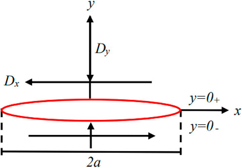
FIGURE 1. Discontinuity of constant displacement of fracture surface.
The displacement and stress caused by the displacement discontinuity (Dx, Dy) of the fracture to any point i in the two-dimensional plane are expressed as follows:
where f(x,y) is:
where σxx, σyy, σxy represent the normal stress along the x, y, and x-y plane directions; ν represents Poisson’s ratio; G represents shear modulus; f(x,y) represents the analytical solution to the constant displacement discontinuity problem, f′x and f′y are the first-order derivatives of f(x,y), f′xx, f′xy, and f′yy are the second-order derivatives of f(x,y), and f′xyy and f′yyy are The third derivative of f(x,y).
The fracture curve in the plane is discretely and uniformly divided into N small units, and the boundary units are represented by two quantities, s-n and x-y, as shown in Figure 2.
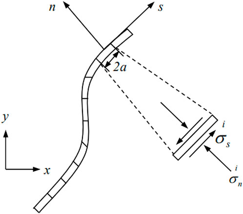
FIGURE 2. Stress and displacement components of the boundary element of the curved fracture segment.
The fracture is subjected to a certain pressure, and the displacement discontinuity component is expressed as follows:
The expressions of stress and displacement at the midpoint of element i are as follows:
For the 4 boundary element components, we need to obtain 2 components at the same time to solve, giving 2 N linear algebraic equations based on N discretized elements. The stress component is represented by Eq. 7, and the displacement component is represented by Eq. 8, thereby obtaining 2 N displacement discontinuities.
Compared with finite element and discrete element methods, the displacement discontinuous boundary element method has higher computational efficiency, and the numerical simulation accuracy is not affected by the complexity of the natural fracture network. Unfortunately, the displacement discontinuous boundary element method cannot consider the effect of non-uniform pore pressure when simulating fracture propagation. This study focuses on the mechanism of the interaction between hydraulic fractures in parent and child wells, so the model is solved using the displacement discontinuity boundary element method, ignoring the effect of pore pressure.
To judge the fracture propagation of rock fractures, it is the key to determine the stress intensity factor. The rock is fractured by an external force, which will cause stress concentration at the fracture tip. Rock fractures can be divided into three types: open type (type I), slip type (type II), and tear type (type III) (Zhou et al., 2019). The stress intensity factor can be used to characterize the stress field and displacement field at the fracture tip (Irwin, 1957). KI, KII, and KIII are the stress intensity factors of three types of fracture tips, respectively, where KI and KII can be expressed as:
The maximum circumferential stress criterion is used to judge the direction of fracture initiation and extension (Erdogan and Sih, 1963), where the stress expression is as follows:
According to the maximum circumferential stress criterion, the fracture will start in the direction of the maximum circumferential stress σθ, where the maximum circumferential stress is:
When the circumferential stress in the direction of the fracture initiation angle θ reaches the maximum value, that is, the critical value σc, the fracture starts to propagate forward. From this, it can be obtained that the conditions for judging fracture propagation according to the maximum circumferential stress criterion are:
Sneddon et al. deduced the induced stress field generated by a single elliptical fracture around a two-dimensional uniform elastic medium under the action of uniform water pressure without considering the fluid loss in the fracture and the pressure drop loss of the plate flow (Sneddon, 1946; Sneddon and Elliot, 1946). As shown in Figure 3, The analytical solution of the induced stress field generated by hydraulic fractures can be expressed as:
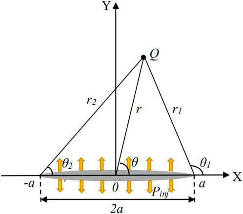
FIGURE 3. Schematic diagram of the calculation of the induced stress field around the fracture.
Pinj represents the fluid pressure in the fracture; σx, σy, τxy represent the x-direction stress component, the y-direction stress component, and the shear stress component in the induced stress field.
(Pinj=-4MPa; a = 1 m; x = 0.8 m; y = 0 m∼10 m).
It can be seen from Figure 4 that the numerical model of hydraulic fracture propagation established in this paper is basically consistent with the numerical simulation results of the stress field and the calculation results of the analytical solution, thus verifying the accuracy of the model.

FIGURE 4. Comparison of simulation results between analytical and numerical solutions.
The reservoir is assumed to be infinite and isotropic. Infill horizontal well technology refers to drilling a new horizontal well parallel to a parent well, and performing hydraulic fracturing reservoir reconstruction on the child well, to exploit the remaining oil areas in low-permeability reservoirs and dead oil under the parent well pattern as much as possible. According to the characteristics of infill horizontal wells, this paper establishes a two-dimensional plane hydraulic fracture propagation model as shown in Figure 5 The initial fractures of parent wells are blue, and the artificial fractures generated by hydraulic fracturing of child wells, that is, infill horizontal wells, are orange, the natural fractures in the reservoir are green. The maximum and minimum horizontal principal stresses are uniformly and symmetrically applied to the model boundary, and the simulation parameters used for hydraulic fracturing fracture propagation are shown in Table 1. The simulation parameters in Table 1 are determined according to the field operation characteristics of infill horizontal wells and concerning previous studies (Lindsay et al., 2018; Roussel et al., 2013; Wang et al., 2022). Note that the compressive stress is assumed to be negative and the tensile stress to be positive.
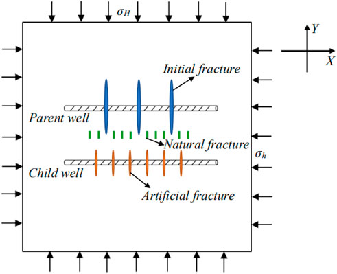
FIGURE 5. Simulation model of hydraulic fracture propagation in infill horizontal wells.
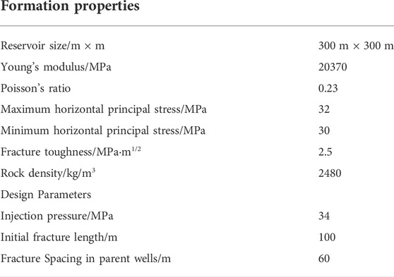
TABLE 1. Hydraulic fracturing simulation parameters.
Fracture spacing is an important parameter for staged multi-cluster fracturing. Keeping the initial fracture parameters of the parent well unchanged, by changing the distance between the artificial fracture and the initial fracture, the propagation of a single artificial fracture in the child well is firstly studied. Figure 6 shows the fracture propagation trajectory of a single fracture in a child well at different positions, and the corresponding stress field is shown in Figure 7 and Figure 8. It can be seen from Figure 6 that the distance between the initial fracture and the artificial fracture will affect the propagation trajectory of the fracture. When the distance is small, the initial fracture will attract the artificial fracture, causing the artificial fracture to deflect to the side of the initial fracture.
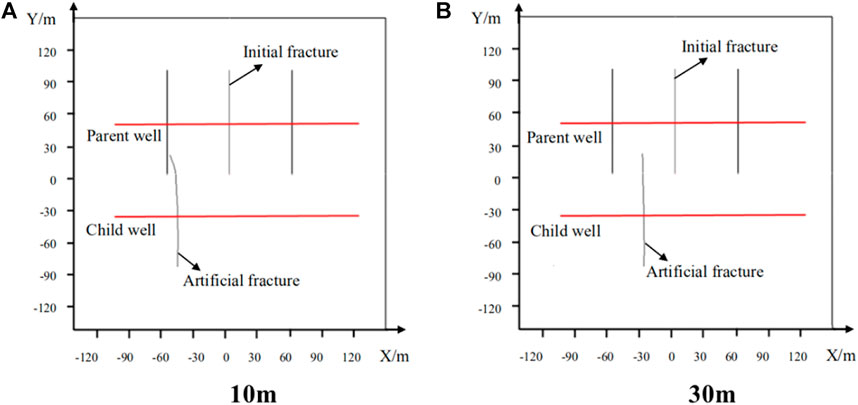
FIGURE 6. The propagation trajectory of a single artificial fracture at different positions.

FIGURE 7. Normal stress field distribution in X-axis direction of single artificial fracture propagation.
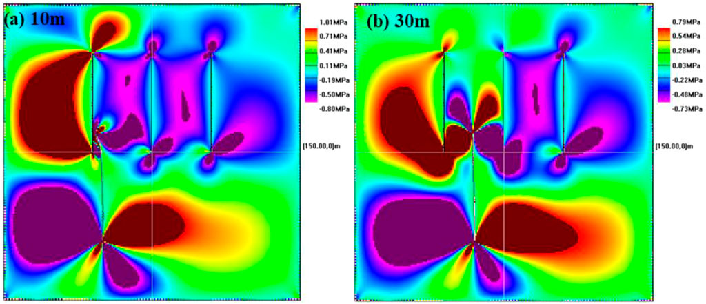
FIGURE 8. Distribution of shear stress field for single artificial fracture propagation.
Figure 7 and Figure 8 show that the distribution of the normal stress field and shear stress field around the fracture shows that when the fracture distance is relatively short, the weak surface of the initial fracture of the parent well will induce the artificial fracture of the child well, and the tensile stress concentration area at the tip of the artificial fracture will decrease, and the shear stress at the fracture tip is enhanced, which causes the artificial fracture to approach the weak surface of the original fracture in the parent well, and the two fractures have easily colluded with each other. Therefore, when infilling horizontal wells and fracturing, the relative positions of artificial fractures and initial fractures should be judged to avoid communication between fractures.
By changing the fracture spacing of hydraulic fractures in infilling horizontal wells, the propagation of hydraulic fractures in the case of multi-cluster fracturing in child wells is analyzed. The fracturing sequence of child wells is set to fracturing from left to right. Figure 9 shows the fracture trajectory under the competitive expansion of multiple artificial fractures, and the corresponding stress field is shown in Figure 10 and Figure 11 of which Figure 9C is the initial fracture of no parent well comparison group. Figure 9 shows that the fracture spacing has a great influence on the propagation trajectory of hydraulic fractures. Compared with the control group without initial fractures, a complex interaction occurs between the initial fractures in the parent well and the hydraulic fractures in the child well, leading to the fact that the originally mutually exclusive artificial fractures may be induced by the initial fractures to approach each other (Figure 9B and Figure 9C). The smaller the fracture spacing, the more obvious the mutual interference between the hydraulic fractures and the initial fractures, and the larger the hydraulic fracture deflection angle. When the fracture spacing is too small, the hydraulic fractures will communicate with each other near the wellbore (Figure 9D).
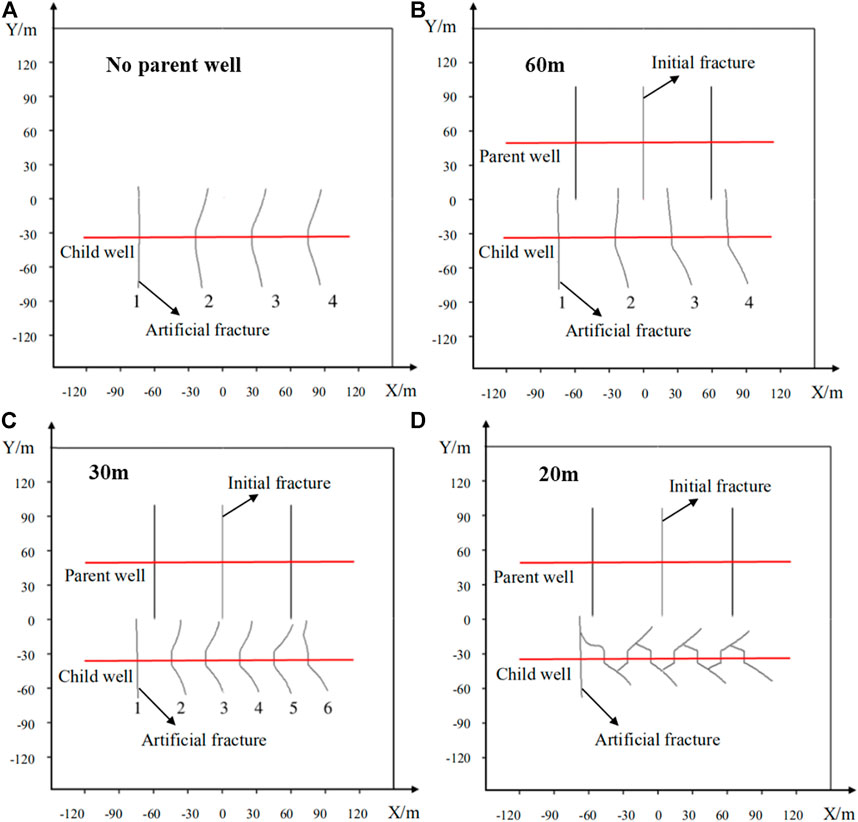
FIGURE 9. Hydraulic fracture propagation trajectories under different fracture spacings.
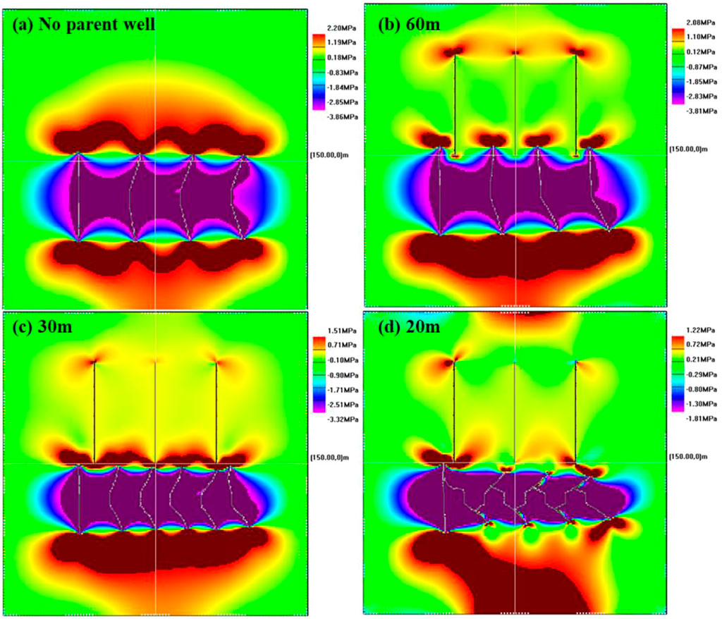
FIGURE 10. Normal stress field distribution in X-axis direction around artificial fractures under different fracture spacings.
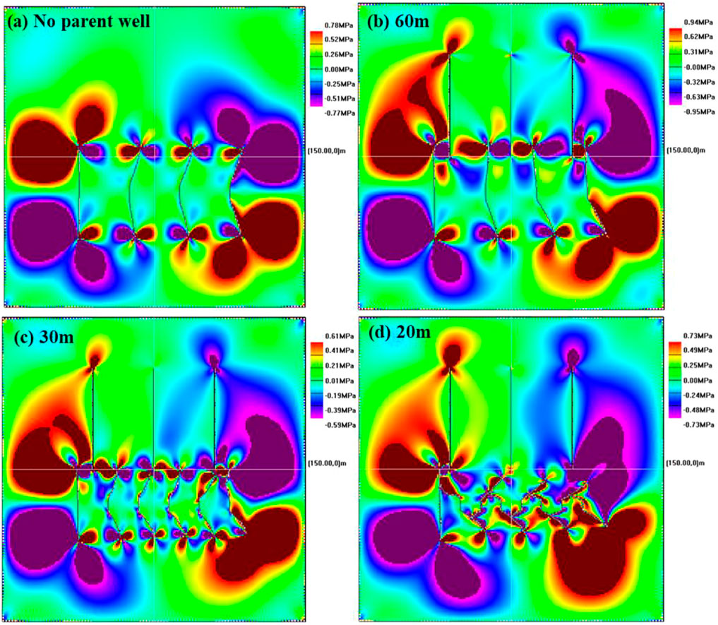
FIGURE 11. Distribution of shear stress field around artificial fractures with different fracture spacings.
Figure 10 and Figure 11 show that the smaller the hydraulic fracture spacing, the greater the stress interference effect, and the rational use of the stress interference effect can increase the complexity of the fracture network. If the fracture spacing is too small, the tensile stress at the tip of the hydraulic fracture decreases, and the compressive stress on both sides increases, which is not conducive to the extension and expansion of the fracture, and the fractures are easy to attract and communicate with each other. When the fracture spacing in Figure 10D and Figure 11D is 20 m, the normal stress and shear stress at the tip of the artificial fracture in the middle is small, and the mutual interference between fractures hinders the fracture extension. Therefore, reasonable fracture spacing during staged multi-cluster fracturing in child wells will maximize the complexity of the artificial fracture network and improve oil recovery.
The distance between the child well and the parent well may affect the inter-fracture interference. The fracture spacing is fixed, and the fracture propagation under different well spacing is analyzed. The simulation results of fracture trajectory are shown in Figure 12 and the simulation results of stress field are shown in Figure 13 and Figure 14. Comparing Figure 12A and Figure 12D, it can be seen that when the well spacing is large, the initial fracture of the parent well will not affect the fracture of the child well. With the shortening of well spacing, the initial fractures of parent wells begin to interfere with the propagation trajectory of hydraulic fractures in child wells. The shorter the well spacing, the stronger the interference effect, the easier it is for hydraulic fractures to attract each other, and even the phenomenon of inter-fracture communication. Reducing the well spacing can increase the stress interference between wells and make the fractures interact, which is conducive to the formation of complex fracture network between wells.
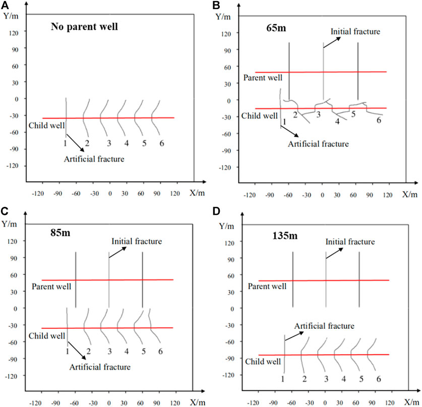
FIGURE 12. Fracture propagation trajectories at different well spacings.
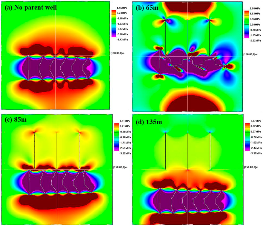
FIGURE 13. Normal stress distribution in the X-axis direction at different well spacings.
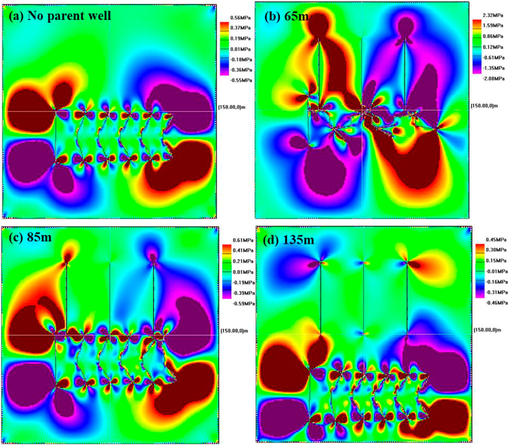
FIGURE 14. Distribution of shear stress under different well spacing.
Figure 13 and Figure 14 show that when the well spacing is small, the stress field distribution around the hydraulic fracture is greatly interfered with by the initial fracture of the parent well. The tensile stress concentration area at the tip of the artificial fracture is greatly reduced, and the fractures communicate with each other in the compressive stress area, so it may be difficult for fracture initiation and extension. When the two wells are far apart, compared with the control group without initial fractures, the stress zone where the hydraulic fractures are located is hardly affected by the initial fracture stress field of the parent well.
Assuming that the natural fractures are closed in the initial state, the pressure inside the fractures is zero, and the fracture spacing is 10 m, the effect of the natural fracture length on the propagation law of hydraulic fractures in child wells is studied by changing the initial length of the natural fractures.
Figure 15 shows the initiation and extension of hydraulic fractures with different initial lengths of natural fractures. It can be seen that the propagation of artificial fractures can induce the initiation and extension of nearby natural micro-fractures, and some natural fractures will communicate with artificial fractures. Since the fracturing sequence is set from left to right, the stress interference area first changes from the left area, so the natural fractures in the left first fracturing area extend longer, and the right rear fracturing area may induce insufficient stress, resulting in natural fractures. The fracture extension distance is getting shorter and shorter, even without fracture initiation. The comparison shows that the longer the initial length of the natural fracture is, the longer the final length of the natural fracture that initiates and extends, and the extension of the natural fracture is divergent toward the parent well.
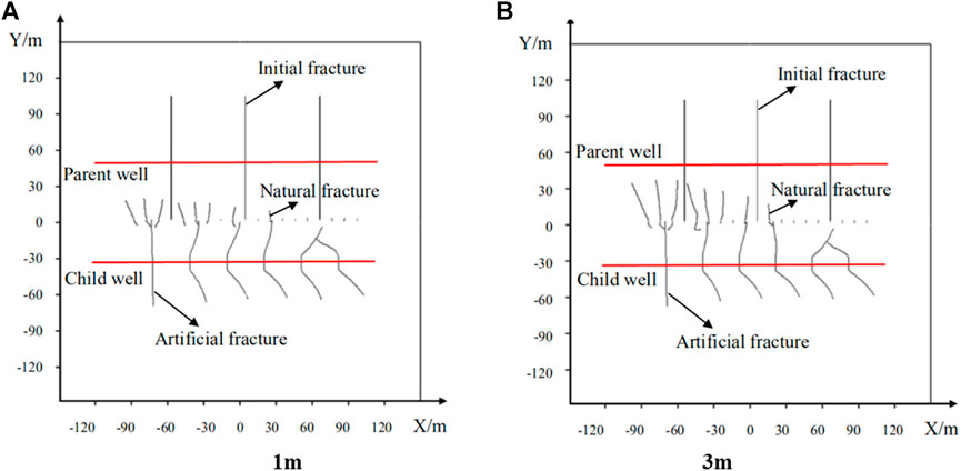
FIGURE 15. Fracture propagation trajectories under different initial lengths of natural fractures.
Figure 16 shows the stress field distribution when the natural fracture length is 1 m. It can be seen that the two tips of natural fractures are located in the stress concentration area, and the upper end is mainly located in the tensile stress concentration area. The natural fracture continues to expand upward and is prone to shear tensile failure. The lower end is located in the compressive stress concentration area. It is difficult to initiate fractures and extend, and it is easier to extend in the direction of the initial fractures in a divergent manner, while the stress values around the fractures without fracture initiation are close to the in-situ stress state.
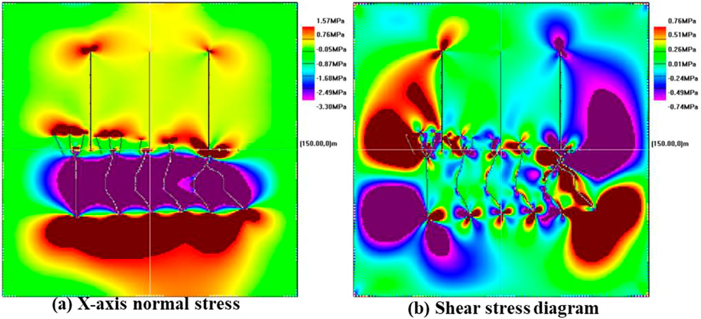
FIGURE 16. Stress field distribution of natural fractures with an initial length of 1 m.
The length of natural fractures is fixed, and the natural fractures are densely arranged by changing the fracture spacing, and the influence of natural fracture density on the propagation of hydraulic fractures is analyzed. From Figure 17 of the fracture propagation trajectory, it can be seen that regardless of the density of natural fractures, the natural fractures in the pre-pressurized area on the left can initiate and extend, while most of the natural fractures in the post-pressurized area on the right do not initiate and extend. The length of natural fracture extension is not greatly affected by the density of natural fractures. As shown in Figure 17A, when natural fractures are densely distributed, individual fractures will stop extending after a certain distance due to the influence of surrounding natural fractures, while some natural fractures will communicate with initial fractures and hydraulic fractures, resulting in child wells communicate between wells, thereby reducing fracturing efficiency.
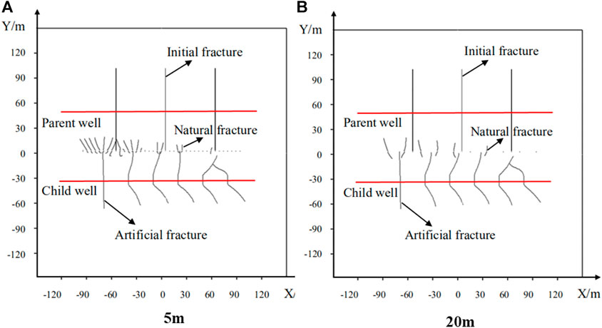
FIGURE 17. Fracture propagation trajectories under different natural fracture densities.
From the stress field distribution results in Figure 18 and Figure 19, it can be seen that the tensile stress area at the tip of the natural fracture in the pre-pressed area on the left is larger, so the natural fracture is more likely to initiate and expand to the parent well under the effect of the induced stress field. However, the natural fracture induced stress in the right back pressure region is obviously insufficient, so most of them do not initiate and propagate.
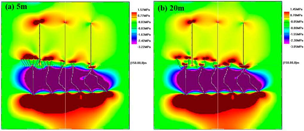
FIGURE 18. Normal stress in the X-axis direction under different natural fracture densities.
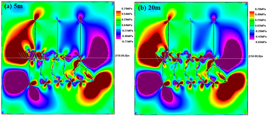
FIGURE 19. Distribution of shear stress under different natural fracture densities.
Based on the theory of linear elasticity and rock fracture mechanics, combined with the boundary element displacement discontinuity method, a simulation model of hydraulic fracturing fracture propagation in infill horizontal wells is established. Using this model, this paper analyze different factors on the propagation of hydraulic fractures in infill horizontal wells. The main simulation results are as follows:
1) The fracture spacing and relative position of hydraulic fractures in infill horizontal wells will have a significant impact on the fracture propagation trajectory. The smaller the fracture spacing is, the larger the hydraulic fracture deflection angle is. Too small fracture spacing may cause hydraulic fractures to communicate with each other in the near-wellbore zone. Reasonable fracture spacing of infilling horizontal wells can increase the complexity of the fracture network.
2) The shorter the well spacing between the infill horizontal well and the parent well is, the stronger the inter-fracture stress interference effect is. Reasonable reduction of well spacing can increase the effect of stress interference and is conducive to the formation of complex fracture networks. Too small well spacing may cause fracture communication between wells and reduce hydraulic fracturing efficiency.
3) Under the action of induced stress, natural fractures will initiate and extend and communicate with hydraulic fractures, and the fracture propagation pattern is divergent along the initial fracture direction of the parent well. The natural fractures in the pre-compression area are more likely to initiate and propagate under the action of induced stress.
4) Under the action of hydraulic fracture-induced stress, the longer the initial length of natural fractures is, the longer the final length of natural fractures is. The natural fracture density has little effect on the natural fracture extension length and fracture shape.
The original contributions presented in the study are included in the article/supplementary material, further inquiries can be directed to the corresponding author.
HW: Writing—original draft, Formal analysis, Conceptualization. EL: Methodology, Software. TY: Methodology, Investigation. LQ: Writing—review and editing, Resources. JL: Conceptualization, Methodology.
This work was supported by the National Natural Science Foundation of China (Grant Nos. 51934005, 51874242, 52174029).
The authors EL, LQ, and JL were employed by Shaanxi Yanchang Petroleum (Group) Co., Ltd. The author TY was employed by Xi’an Changqing Chemical Group Co., Ltd.
The remaining authors declare that the research was conducted in the absence of any commercial or financial relationships that could be construed as a potential conflict of interest.
All claims expressed in this article are solely those of the authors and do not necessarily represent those of their affiliated organizations, or those of the publisher, the editors and the reviewers. Any product that may be evaluated in this article, or claim that may be made by its manufacturer, is not guaranteed or endorsed by the publisher.
Beugelsdijk, L. J. L., De Pater, C. J., and Sato, K. (2000). “Experimental hydraulic fracture propagation in a multifracture medium,” in SPE Asia Pacific conference on integrated modelling for asset management. One Petro.
Bieniawski, Z. T. (1967). Mechanism of brittle fracture of rock: Part I—theory of the fracture process[C]. Int. J. Rock Mech. Min. Sci. Geomechanics Abstr. 4 (4), 395–406. doi:10.1016/0148-9062(67)90030-7
Crouch, S. (1976). Solution of plane elasticity problems by the displacement discontinuity method, Infinite body solution. J. Numer. Methods Eng. 10 (2), 301–343. doi:10.1002/nme.1620100206
Dehghan, A. N., Goshtasbi, K., Ahangari, K., and Jin, Y. (2016). Mechanism of fracture initiation and propagation using a tri-axial hydraulic fracturing test system in naturally fractured reservoirs. Eur. J. Environ. Civ. Eng. 20 (5), 560–585. doi:10.1080/19648189.2015.1056384
Ding, D. Y., Farah, N., Bourbiaux, B., Wu, Y., and Mestiri, I. (2018). Simulation of matrix/fracture interaction in low-permeability fractured unconventional reservoirs. SPE J. 23 (04), 1389–1411. doi:10.2118/182608-pa
Duan, K., Li, Y., and Yang, W. (2021). Discrete element method simulation of the growth and efficiency of multiple hydraulic fractures simultaneously-induced from two horizontal wells[J]. Geomechanics Geophys. Geo-Energy Geo-Resources 7 (1), 1–20. doi:10.1007/s40948-020-00196-4
Erdogan, F., and Sih, G. C. (1963). On the crack extension in plates under plane loading and transverse shear. J. Basic Eng. 85, 519–525. doi:10.1115/1.3656897
Guo, Y., Deng, P., Yang, C., Chang, X., Wang, L., and Zhou, J. (2018). Experimental investigation on hydraulic fracture propagation of carbonate rocks under different fracturing fluids. Energies 11 (12), 3502. doi:10.3390/en11123502
He, L., Zhongxiao, L., Suling, W., Xu, J., and Zhao, C. (2015). Hydraulic fracture initiation mechanism in the definite plane perforating technology of horizontal well[J]. Petroleum Explor. Dev. 42 (6), 869–875. doi:10.1016/S1876-3804(15)30084-7
He, W., and Hayatdavoudi, A. (2018). A comprehensive analysis of fracture initiation and propagation in sandstones based on micro-level observation and digital imaging correlation. J. Petroleum Sci. Eng. 164, 75–86. doi:10.1016/j.petrol.2018.01.041
Hou, B., Zhang, R., Zeng, Y., Fu, W., Muhadasi, Y., and Chen, M. (2018). Analysis of hydraulic fracture initiation and propagation in deep shale formation with high horizontal stress difference. J. Petroleum Sci. Eng. 170, 231–243. doi:10.1016/j.petrol.2018.06.060
Huang, J., Safari, R., Mutlu, U., Kevin, B., Ingo, G., and Mark, M. (2014). “Natural-hydraulic fracture interaction: Microseismic observations and geomechanical predictions[C],” in SPE/AAPG/SEG Unconventional Resources Technology Conference. One Petro.
Irwin, G. (1957). Analysis of stresses and strains near the end of a crack traversing a plate. J. Appl. Mech. 243, 361–364. doi:10.115/1.4011547
Kresse, O., Weng, X., Wu, R., and Gu, H. (2012). “Numerical modeling of hydraulic fractures interaction in complex naturally fractured formations[C],” in 46th US rock mechanics/geomechanics symposium. One Petro.
Lam, K. Y., and Phua, S. P. (1991). Multiple crack interaction and its effect on stress intensity factor. Eng. Fract. Mech. 40 (3), 585–592. doi:10.1016/0013-7944(91)90152-q
Lindsay, G., Miller, G., Xu, T., Shan, D., and Baihly, J. (2018). “Production performance of infill horizontal wells vs. pre-existing wells in the major US unconventional basins[C],” in SPE hydraulic fracturing technology conference and exhibition. OnePetro.
Liu, Z., Wang, S., Ye, H., Yang, L., Fan, F., Lian, H., et al. (2021). Experimental study on the effects of pre-cracks, fracturing fluid, and rock mechanical characteristics on directional hydraulic fracturing with axial pre-cracks[J]. Geomechanics Geophys. Geo-Energy Geo-Resources 7 (2), 1–14. doi:10.1007/s40948-021-00225-w
Lorenz, J. C., Teufel, L. W., and Warpinski, N. R. (1991). Regional fractures I: A mechanism for the formation of regional fractures at depth in flat-lying reservoirs[J]. AAPG Bull. 75 (11), 1714–1737. doi:10.1306/0C9B29E3-1710-11D7-864000102C1865D
Roussel, N. P., Florez, H. A., and Rodriguez, A. A. (2013). “Hydraulic fracture propagation from infill horizontal wells[C],” in SPE annual technical conference and exhibition. OnePetro.
Sneddon, I. N., and Elliot, H. A. (1946). The opening of a Griffith crack under internal pressure. Q. Appl. Math. 4 (3), 262–267. doi:10.1090/qam/17161
Sneddon, I. N. (1946). The distribution of stress in the neighbourhood of a crack in an elastic solid[J]. Proc. R. Soc. Lond. Ser. A. Math. Phys. Sci. 187 (1009), 229–260. doi:10.1098/rspa.1946.0077
Tan, P., Jin, Y., Yuan, L., Xiong, Z. Y., Hou, B., Chen, M., et al. (2019). Understanding hydraulic fracture propagation behavior in tight sandstone–coal interbedded formations: An experimental investigation. Pet. Sci. 16 (1), 148–160. doi:10.1007/s12182-018-0297-z
Wang, H. Y., Zhou, D., Xu, J., Liu, S., Liu, E., and Gao, Q. (2021). “An optimal design algorithm for proppant placement in slickwater fracturing[C],” in Abu Dhabi International Petroleum Exhibition & Conference. OnePetro.
Wang, H., Zhou, D., Liu, S., Wang, X., Ma, X., and Yao, T. (2022). Hydraulic fracture initiation for perforated wellbore coupled with the effect of fluid seepage. Energy Rep. 8, 10290–10298. doi:10.1016/j.egyr.2022.08.011
Wang, W., Olson, J. E., and Prodanovic, M. (2013). “Natural and hydraulic fracture interaction study based on semi-circular bending experiments[C],” in SPE/AAPG/SEG Unconventional Resources Technology Conference. One Petro.
Wu, K., Wu, B., and Yu, W. (2018). Mechanism analysis of well interference in unconventional reservoirs: Insights from fracture-geometry simulation between two horizontal wells. SPE Prod. Operations 33 (01), 12–20. doi:10.2118/186091-pa
Wu, R., Kresse, O., Weng, X., Cohen, C., and Gu, H. (2012). “Modeling of interaction of hydraulic fractures in complex fracture networks[C],” in SPE Hydraulic Fracturing Technology Conference. One Petro.
Yan, T., Li, W., and Bi, X. (2011). An experimental study of fracture initiation mechanisms during hydraulic fracturing. Pet. Sci. 8 (1), 87–92. doi:10.1007/s12182-011-0119-z
Yang, W., Li, S., Geng, Y., Zhou, Z., Li, L., Gao, C., et al. (2021). Discrete element numerical simulation of two-hole synchronous hydraulic fracturing[J]. Geomechanics Geophys. Geo-Energy Geo-Resources 7 (3), 1–15. doi:10.1007/s40948-021-00257-2
Yao, Y., Guo, Z., Zeng, J., Li, D., Lu, J., Liang, D., et al. (2021). Discrete element analysis of hydraulic fracturing of methane hydrate-bearing sediments. Energy fuels. 35 (8), 6644–6657. doi:10.1021/acs.energyfuels.1c00248
Zheng, H., Pu, C., and Sun, C. (2020). Study on the interaction between hydraulic fracture and natural fracture based on extended finite element method[J]. Eng. Fract. Mech. 230, 106981. doi:10.1016/j.engfracmech.2020.106981
Zhou, D., Wang, H., He, Z. X., Liu, Y., Liu, S., Ma, X., et al. (2020). Numerical study of the influence of seepage force on the stress field around a vertical wellbore. Eng. Appl. Comput. Fluid Mech. 14 (1), 1489–1500. doi:10.1080/19942060.2020.1835733
Zhou, D., Zheng, P., Yang, J., Li, M., Xia, Y., Cai, W., et al. (2019). Optimizing the construction parameters of modified zipper fracs in multiple horizontal wells. J. Nat. Gas Sci. Eng. 71, 102966. doi:10.1016/j.jngse.2019.102966
Keywords: hydraulic fracturing, boundary element method, numerical simulation, infill horizontal wells, fracture propagation
Citation: Liu E, Yao T, Qiao L, Li J, Wang H and Gao Q (2022) Research on the propagation mechanism of hydraulic fractures in infill horizontal wells. Front. Earth Sci. 10:1026551. doi: 10.3389/feart.2022.1026551
Received: 24 August 2022; Accepted: 05 September 2022;
Published: 23 September 2022.
Edited by:
Jinze Xu, University of Calgary, CanadaReviewed by:
Ran Li, University of Calgary, CanadaCopyright © 2022 Liu, Yao, Qiao, Li, Wang and Gao. This is an open-access article distributed under the terms of the Creative Commons Attribution License (CC BY). The use, distribution or reproduction in other forums is permitted, provided the original author(s) and the copyright owner(s) are credited and that the original publication in this journal is cited, in accordance with accepted academic practice. No use, distribution or reproduction is permitted which does not comply with these terms.
*Correspondence: Haiyang Wang, d2FuZ19oYWlfeWFuZ0AxMjYuY29t
Disclaimer: All claims expressed in this article are solely those of the authors and do not necessarily represent those of their affiliated organizations, or those of the publisher, the editors and the reviewers. Any product that may be evaluated in this article or claim that may be made by its manufacturer is not guaranteed or endorsed by the publisher.
Research integrity at Frontiers
Learn more about the work of our research integrity team to safeguard the quality of each article we publish.