 Huaibin Li
 Xingdong Zhao
 Bibo Dai2
 Qiankun Zhu
95% of researchers rate our articles as excellent or good
Learn more about the work of our research integrity team to safeguard the quality of each article we publish.
Find out more
ORIGINAL RESEARCH article
Front. Earth Sci. , 28 September 2022
Sec. Geohazards and Georisks
Volume 10 - 2022 | https://doi.org/10.3389/feart.2022.1024240
This article is part of the Research Topic Geological Disasters and Its Prevention in Deep Mining View all 16 articles
The failure of surrounding rock in deep hard rock roadway is closely related to mining disturbance. In this study, the 13# stope ramp of −767 m level (at a buried depth of 1,197 m) at Hongtoushan copper mine was taken as the engineering background, a comprehensive analysis method of numerical analysis and borehole detection was put forward, and the evolution law of fracture depth of the ramp surrounding rock under the mining influence was obtained. The results show that the maximum tangential stress and fracture depth of the ramp surrounding rock on both sidewalls increase slowly at the initial mining stage. When the ore body above the ramp is mined, the maximum tangential stress and fracture depth of the ramp surrounding rock on both sidewalls increase rapidly, and the two parameters are positively correlated. Based on this, the ratio of the maximum tangential stress of the surrounding rock to the uniaxial compressive strength of intact rock (σθmax/σc) and the equivalent radius (a) of the roadway were used as parameters, and an equation for the fracture depth of the roadway surrounding rock was proposed. Through the case analysis, the results show that the proposed equation of fracture depth of the roadway surrounding rock has good prediction accuracy. This study enriches the research on the stability and failure mechanism of the roadway surrounding rock under the mining disturbance, and provides new basis for the support design of mining roadways.
The overhand cut-and-fill mining method has been widely used in deep metal deposits, and the transportation roadway has generally been arranged at the footwall of the ore body. The deep stope and the roadway surrounding rock are often in a complex stress environment (i.e., high ground stress, high ground temperature, high osmotic pressure, and strong mining disturbance). When the mining stress is greater than the strength of the surrounding rock of the stope (roadway), the spalling, rockburst and other failures of the surrounding rock can be induced easily. As a result, the ore loss and dilution, equipment damage and personnel casualties can be caused, which seriously hinders the normal production of the mine (Read, 2004; Zhao et al., 2013; Abdellah et al., 2014; Zheng et al., 2015; Wei et al., 2022).
At present, research on the failure of the surrounding rock of stope (roadway) induced by deep mining has been widely conducted, and some progress in the mechanics and mining engineering has been obtained. Through borehole television monitoring and acoustic testing, Wang et al. (2015) studied the damage range of roadway surrounding rock, and concluded that the damage range of the roadway surrounding rock under the mining influence is larger than that without mining influence. Based on the numerical simulation method, Zhang and Mitri (2008) explored the key factors affecting the plastic zone of the surrounding rock in the footwall transport roadway. It was found that under the mining influence, the plastic zone of the surrounding rock of the footwall transport roadway increases with the increase of the buried depth of the roadway, and it also increases with the decrease of the distance between roadway and stope. Through the numerical simulation method, Jia et al. (2017) studied the mechanical mechanism and distribution characteristics of the plastic zone of roadway surrounding rock under the non-uniform stress field. The results showed that when the stress around the roadway is greater than the strength of the surrounding rock and the ratio of principal stress around the roadway is large, the shear failure occurs in the surrounding rock, and a butterfly-shaped plastic zone can be formed. Abdellah et al. (2011) evaluated the issue of haulage drift safety in mining activities using probabilistic methods. Aiming at the Linglong gold mine in China, Cai and Lai (2003) investigated the main influencing factors of the stability of the transport roadway by the coupled data mining techniques, and analyzed the acoustic emission signals and monitoring results. Liu et al. (2019) simulated coal seams with different dip angles through the FALC3D software, and discussed the characteristics of floor failure under the mining influence. Waclawik et al. (2017) monitored the stress of the surrounding rock of the roadway under long-wall mining. It was concluded that the stress of surrounding rock changes with the advance of the working face.
The stress change of the surrounding rock in underground engineering is closely related to rock failure. Researchers have conducted many studies on the relationship between stress and failure of surrounding rock in engineering. Based on the damage situation of the gold mine in South Africa, Ortlepp and Stacey (1994), Ortlepp (2000) divided the damage degree of the roadway by using the ratio of the maximum principal stress to the uniaxial compressive strength. Specifically, when the maximum principal stress is equal to 0.2σf, the spalling failure occurs in the surrounding rock, when it exceeds 0.4σf, rockburst occurs in the surrounding rock. By using maximum principal stress, minimum principal stress and peak strength σf, Wagner and Wiseman (1980) proposed a concept of stress concentration factor. It is concluded that when the stress concentration factor SF is equal to or greater than 0.8, the spalling failure occurs in the roadway surrounding rock. Hoek and Brown (1980) made a more detailed classification of the damage degree of the roadway by using the ratio of the maximum tangential stress of surrounding rock to the uniaxial compressive strength of rock (σθmax/σc). When σθmax/σc is equal to 0.34, slight spalling failure occurs in the surrounding rock, when σθmax/σc is equal to 0.42, severe spalling failure occurs in the surrounding rock. Dowding and Andersson (1986) analyzed five typical cases of spalling failure of surrounding rock in tunnels. It is believed that when the ratio of the maximum tangential stress of surrounding rock caused by tunnel excavation to the uniaxial compressive strength of rock (σθmax/σc) exceeds 0.35, the spalling failure of surrounding rock occurs, when σθmax/σc exceeds 0.5, the weak or medium rockburst occurs in surrounding rock, when σθmax/σc exceeds 1.0, the strong rock burst occurs in surrounding rock. Based on field-measured data, Martin (1993), Martini et al. (1997), and MartinChristiansson (2009) and Diederichs (2007) fitted empirical formulas with stress intensity ratio and roadway size as parameters, and calculated the fracture depth of the roadway surrounding rock. Perras and Diederichs (2016) predicted the excavation damage zones of the brittle surrounding rock of the underground tunnel by the empirical method and numerical simulation method. Cai and Kaiser (2014) employed numerical simulation and field comparison methods to study the spalling failure strength at the excavation boundary in the field. The results showed that the spalling strength of rock mass at the project site is not 0.4 ± 0.1 times of the uniaxial compressive strength of rock, but generally 0.8 ± 0.05 times of the uniaxial compressive strength of rock. The above research results provide a valuable reference for analyzing the stress, displacement and distribution characteristics of the failure zone of the roadway surrounding rocks under the mining influence. However, there are few studies on the evolution and prediction of the fracture depth of roadway surrounding rock under the influence of deep mining.
The 13# stope ramp of −767 m level (at a buried depth of 1,197 m) at Hongtoushan copper mine, a wide range of spalling failures under the mining influence occurred. Based on this engineering background, the failure mechanism of the ramp surrounding rock was analyzed, and the evolution process of the maximum tangential stress of the ramp surrounding rock during the overhand cut-and-fill mining was obtained by the FLAC3D software. Besides, the fracture depth of the surrounding rock was measured by the borehole detection, the stress-fracture depth evolution process of surrounding rock under the mining influence was comprehensively analyzed, and the equation of rock fracture depth of mining roadway was proposed by using the ratio of the maximum tangential stress of surrounding rock of the roadway to the uniaxial compressive strength of the intact rock (σθmax/σc) and the equivalent radius (a) of the roadway. This study provides a basis for supporting design and judgment of the fracture depth of roadway surrounding rock under the mining influence.
Hongtoushan copper mine is located in the northeast of Liaoning Province, China (Figure 1). At present, it is one of the deepest non-ferrous metal mine in China, with an exploration depth of 1,657 m and a mining depth of 1,257 m. In this mine, the overhand cut-and-fill mining method was adopted. The 13# stope ramp of −767 m level (at a buried depth of 1,197 m) had a stage height of 60 m, a strike length of 50 m, and a stope span of 30 m, and the dip of the stope is 70°. Parallel blast hole rings were fired at a 3 m extracting height in the horizontal panel and using multiple ring sequences. The stope is backfilled with tailings and cement after every slice mined. Access to cut-and-fill stopes is through ramp located in footwall of each stope and inclined at the same dip as the ore body. The horizontal distance between the ramp and 13# stope is about 20 m. The horse-shoe-shaped ramp is a cross-section of 3.0 m width and 2.8 m height. To obtain the distribution of the structural planes in the stope and surrounding rock, the on-site engineering geological survey of the hanging wall, footwall and ore body of the stope was carried out by using the scan line method. The rock samples were taken on-site and the rock mechanical experiments were carried out. The quality of the surrounding rock of the stope was classified by rock mass rating (RMR) and rock mass quality (Q) methods. The results showed that the quality of rock mass was generally good. The mechanical parameters of the ramp surrounding rock were estimated based on the Hoke-Brown strength criterion, as shown in Table 1.
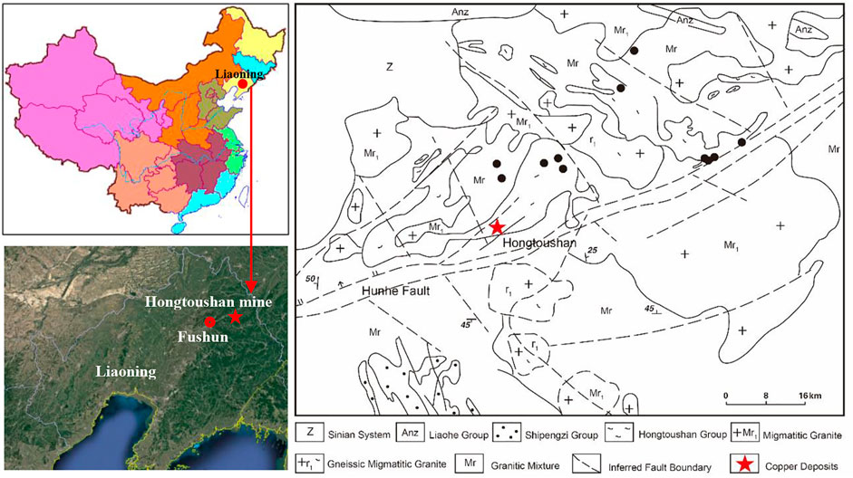
FIGURE 1. Location and regional geology of the Hongtoushan mine.
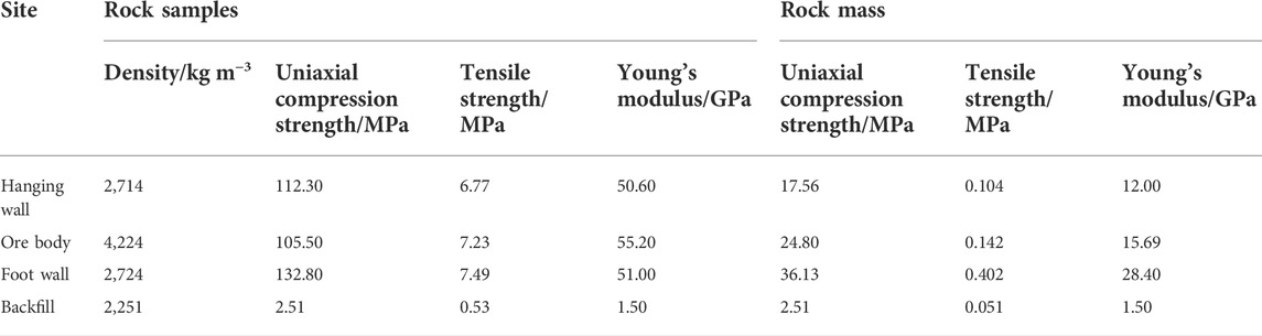
TABLE 1. Mechanical parameters of rock samples and rock mass.
The regression equations of the maximum horizontal principal stress, minimum horizontal principal stress and vertical stress are obtained by hollow inclusion stress relief method in the field as follows (Zhao et al., 2019).
where σh,max, σh,min, and σv (MPa) are the maximum horizontal principal stress, minimum horizontal principal stress, and vertical principal stress, and H is the depth (m). According to Eq. 1, the maximum horizontal principal stress σh,max at −767 m (at a buried depth of 1,197 m) reaches 32.2 MPa with a direction of NW, the minor horizontal principal stress σh,min is 24.4 MPa in the 167°/60° plane, and the vertical principal stress σv is 32.2 MPa.
The ramp of 13# stope was arranged in the hard rock mass of the footwall. Due to its large buried depth and close distance to the stope, this ramp was seriously affected by mining. Figure 2 shows the typical spalling failure of the 13# stope ramp under the mining influence. The ramp excavation breaks the balance of the initial stress field, the stress begins to redistribute, the tangential stress of the ramp surrounding rock increases, the radial stress decreases. As a result, the ramp is in a bidirectional stress state. Under the mining influence, the ramp surrounding rock undergoes several stress adjustments. When the maximum tangential stress in surrounding rock exceeds the strength of the rock mass, the stress-induced brittle failure of surrounding rock can be caused. As it is difficult to obtain the strength of rock mass on-site, Hoek and Brown (1980), Dowding and Andersson (1986), Martin et al. (1999), Cai and Kaiser (2014), and Wang et al. (2012) took the ratio of the maximum tangential stress σθmax to the uniaxial compressive strength σc of intact rock as the basis of brittle failure of hard rock. It can be seen that the brittle failure of hard rock can be described by σθmax/σc. Based on the empirical relationship between σθmax/σc and fracture depth, the maximum tangential stress of the surrounding rock under the mining influence can be obtained by numerical calculation, and the fracture depth of the surrounding rock of the mining roadway can be quickly calculated with the empirical formula. This equation can provide a reference for the support design.
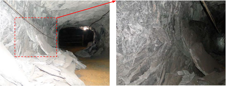
FIGURE 2. Spalling failure of the ramp surrounding rock in the 13# stope.
According to the engineering geological conditions of the 13# stope ramp of −767 m level (at a buried depth of 1,197 m), a numerical simulation model was established. It was assumed that the calculation model was a plane strain model, and the rock mass was homogeneous and isotropic. The size of the model was 200 m × 200 m (width × high), and the model was divided into 87,520 units, as shown in Figure 3. To ensure the calculation accuracy, the grid at the ramp position was encrypted. The dip angle of the ore body was 70° and the thickness was 30 m. The mixed boundary conditions were adopted in the model. The vertical and horizontal displacements were restricted on both sidewalls and the bottom of the model. Stress constraints were applied on both sidewalls and the top of the model, and the linear-elastic model was used for simulation.
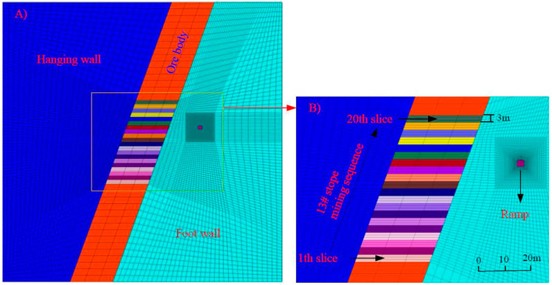
FIGURE 3. Numerical model of the 13# stope and ramp.
The FLAC3D software was used to analyze the evolution process of the tangential stress of the ramp surrounding rock of the stope under the mining influence. During the model calculation, the ramp was excavated first, and then the 13# stope was mined from the bottom to the top layers by layers. There were 20 layers in total, and each layer was 3 m high. After the stress balance was reached after the mining of the previous layer, the backfilling of the next layer was conducted.
Borehole detection technology is an intuitive detection method, which can quickly and accurately identify the development of cracks in surrounding rock. At present, the borehole detection method has been rarely used to observe the failure evolution process of the roadway surrounding rock under the deep mining influence in the existing studies. It is necessary to use the borehole detection method to further reveal the mining-induced failure evolution of roadway surrounding rock.
The ZKXG100-type borehole camera detection device was used on site to detect the fracture depth of the ramp surrounding rock in the 13# stope. Three detection boreholes with a depth of 4 m and a diameter of 40 mm were drilled on the both sidewalls and roof of the ramp. The both sidewalls of the detection boreholes were 1 m high from the floor, with an upward horizontal inclination of 5°. The roof detection boreholes were set perpendicular to the roof. Figure 4 shows the specific layout of the borehole detection. The field observation is from the first layer mining until the end of the 13# stope mining. When mining the ore body below the 14th layer in the 13# stope, the cracks in the ramp surrounding rock were not significantly developed and damaged. Therefore, Figure 9 only shows the detection results when mining the ore body above the 14th layer in the 13# stope.
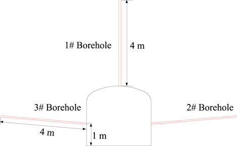
FIGURE 4. Layout of borehole detection.
To analyze the failure evolution process of surrounding rock of the 13# stope ramp under the mining influence, a comprehensive analysis method combining field investigation, numerical analysis and borehole detection was proposed (see Figure 5). In the field investigation, the failure characteristics and occurrence mechanism of the ramp surrounding rock were mainly analyzed to provide detailed data for the establishment of the numerical calculation model and the location of the borehole detection. The numerical analysis was used to study the evolution law of the tangential stress of the ramp surrounding rock under the mining influence. Borehole detection recorded the fracture depth of the ramp surrounding rock when different layers were mined.
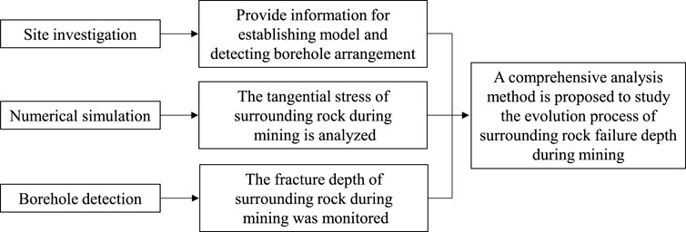
FIGURE 5. Comprehensive analysis method for the fracture depth evolution of the ramp surrounding rock under the mining influence.
To analyze the evolution process of tangential stress of the surrounding rock under mining, measuring points were arranged every 0.2 m along the radial direction 10 m at the left, right and roof of the ramp, and the change of tangential stress at this point was monitored, as shown in Figures 6–8. For simplicity, the compressive stress was set as a positive value and the tensile stress as a negative value.
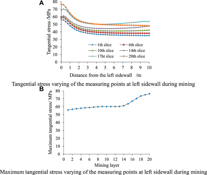
FIGURE 6. Tangential stress varying at left sidewall during mining.
As shown in Figure 6A, with the increase of radial depth, the tangential stress value of the left sidewall first increases slightly, and then begins to decrease. When the depth is about twice the roadway span from the left sidewall, the tangential stress value of this point tends to be stable. As can be seen from Figure 6B, when mining the ore body at the lower part of the ramp, the maximum tangential stress at the left sidewall increases slowly. When mining exceeds the level of the ramp (i.e., the ore body above the 14th layer), the maximum tangential stress increases rapidly, and then tends to be stable. The maximum tangential stress is 76.4 MPa.
As shown in Figure 7, the tangential stress of the right sidewall has the same evolution law as that of the left sidewall. The difference is that the tangential stress of the right sidewall is slightly smaller than that of the left sidewall during the mining of the same layer. After mining the 20th layer, the maximum tangential stress peak value of the right sidewall is 72.4 MPa.
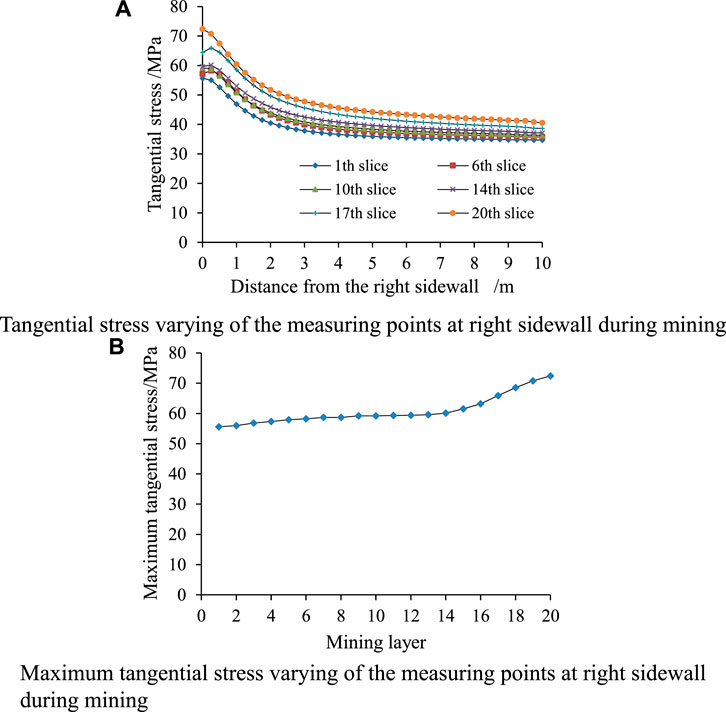
FIGURE 7. Tangential stress varying at right sidewall during mining.
As shown in Figure 8, the tangential stress value is negative near the roof, and the roof is in the tensile stress zone. With the increase of radial depth, the tangential stress value of the roof changes from negative to positive, and then begins to decrease. When the depth is about twice the roadway span from the roof, the tangential stress value at this point tends to be stable. At the initial stage of mining, there is a tension zone on the ramp roof. When mining to the level near the ramp, the tension zone disappears. With the development of mining, the roof tension zone appears again. The maximum tangential stress value of the ramp surrounding rock during the whole mining process is listed in Table 2.
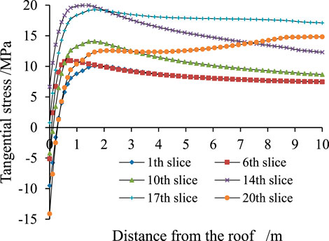
FIGURE 8. Tangential stress varying of roof during mining.
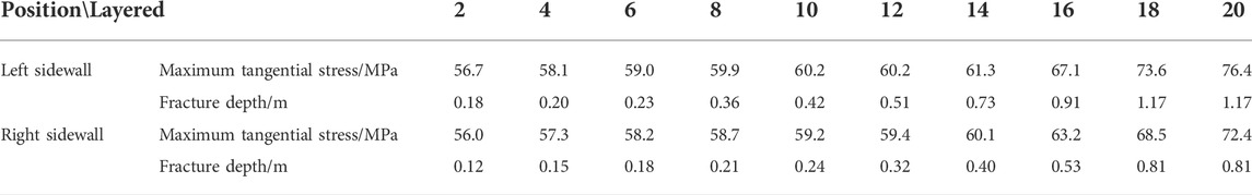
TABLE 2. Comparative analysis of the maximum tangential stress and fracture depth of the ramp surrounding rock.
The damage degree of surrounding rock is mainly judged by observing the development of cracks. The development range of cracks can be regarded as the fracture depth of the surrounding rock. The spalling fracture depth of surrounding rock generally refers to the depth of continuous failure or serious failure of rock mass (Wagner and Wiseman, 1980). Through the borehole detection of the ramp surrounding rock, the failure of surrounding rock in different periods of mining was obtained, as shown in Figure 9. The red line in the figure indicates the crack, the green area indicates the spalling of the borehole wall, and the gray area indicates the spalling of surrounding rock.
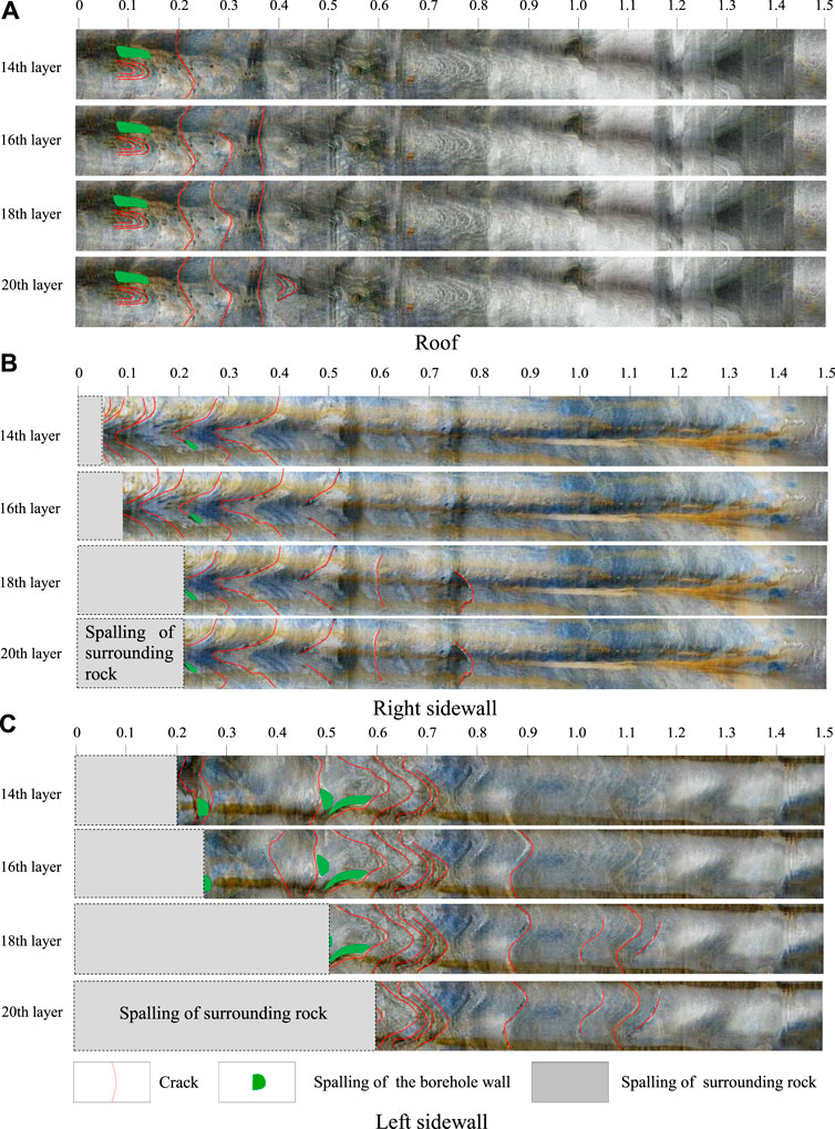
FIGURE 9. Failure of surrounding rock in the 13# stope ramp at different mining layers.
When mining the 14th layer, the mining layers are at the same level as the ramp. There are a few cracks on the inner wall of the 1# borehole (in the roof) from the orifice to the position of 0.24 m, and the cracks above the position of 0.24 m are not obvious. A large number of cracks are developed on the inner wall of the 2# borehole (in the right sidewall) from the orifice to the position of 0.4 m. The spalling with a thickness of 0.05 m in the orifice can be observed, and a small range of spalling appears on the borehole wall at the position of 0.22 m. The cracks above the position of 0.4 m are not developed. A large number of cracks are developed on the inner wall of the 3# borehole (in the left sidewall) from the orifice to the position of 0.73 m. The spalling with a thickness of 0.2 m in the orifice can be observed, and a small range of spalling appears on the borehole wall at 0.25, 0.5, and 0.55 m, respectively. The cracks above the position of 0.73 m are not obvious.
When the 16th layer is mined, the mining layers exceed the level of the ramp. New cracks appear in both sidewalls of the ramp and the roof borehole. Besides, the maximum depth of crack development in the 1# borehole (in the roof) is increased to 0.39 m, and the length of some original cracks is increased slightly. The maximum depth of the failure development in the 2# borehole (in the right sidewall) is increased to 0.53 m, and the depth of spalling failure is increased to 0.09 m. In the 3# borehole (on the left sidewall), the maximum depth of crack development in the 3# borehole is increased to 0.91 m, and the depth of spalling failure is increased to 0.26 m.
When the 18th layer is mined, no new cracks are found in the 1# borehole (in the roof), and only the length of some original cracks is slightly increased. Compared with the previous detection results, new cracks are generated in 2# and 3# boreholes (in the right and left sidewalls), and the crack development depth increases slowly, with the maximum depth of 0.81 and 1.17 m. The new spalling failure occurs in 2# and 3# boreholes (in right and left sidewalls), and the spalling fracture depth is 0.21 and 0.5 m, respectively.
When the 20th layer is mined, new cracks are produced again in the 1# borehole (in the roof), and the maximum depth of crack development increases to 0.44 m. There is no new crack in 2# borehole (in the right sidewall). No new cracks are found in the 3# borehole (in the left sidewall), but the spalling fracture depth is increased to 0.6 m. The fracture depth of the ramp surrounding rock during the whole mining process is summarized in Table 2.
Through the comprehensive analysis method of numerical analysis and borehole detection, the evolution process of the fracture depth of the surrounding rock under the mining influence is analyzed. As shown in Table 2, the fracture depth of the surrounding rock in the stope increases gradually with the increase of the maximum tangential stress of the surrounding rock, and the mining has a greater influence on the fracture depth of the left sidewall than the right sidewall. Combined with the failure mechanism of the ramp surrounding rock, it can be found that the brittle failure of hard rock can be described by σθmax/σc. The linear fitting of the data (the maximum tangential stress and fracture depth in Table 2) is performed, then the equation of the fracture depth of the surrounding rock of the mining roadway can be obtained (see Figure 10) based on the equivalent radius (a) of the roadway and the ratio of the maximum tangential stress of surrounding rock to the uniaxial compressive strength of intact rock (σθmax/σc). When the analyzed roadway section is D-shaped, the effective radius of the roadway should be estimated (Figure 11). The estimated fracture depth of the roadway surrounding rock does not include the distance between the two sidewalls and the boundary of the equivalent circle (△). To verify the accuracy of the proposed equation, four engineering cases affected by mining are analyzed (Table 3), and their relative errors are calculated. Then the total error of all cases is predicted and averaged, and the average relative error is 12.9%. The calculation results of the proposed equation for the fracture depth of surrounding rock in mining roadways are in good agreement with the numerical analysis. It indicates that the proposed equation has great practicability and accuracy in predicting the fracture depth of surrounding rock in mining roadway, which can provide a basis for the support design of the engineering site.
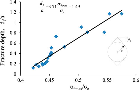
FIGURE 10. The proposed equation of fracture depth of surrounding rock in mining roadway.
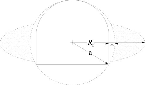
FIGURE 11. The D-shaped tunnel with an effective tunnel radius.
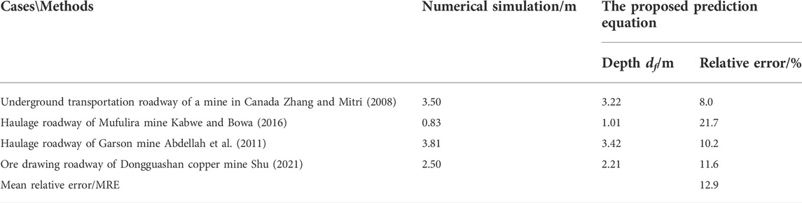
TABLE 3. Comparative analysis of different methods for fracture depth of surrounding rock in engineering.
Through the comprehensive analysis method of numerical analysis and borehole detection, the evolution process of surrounding rock fracture depth of deep mining ramp in Hongtoushan copper mine was studied. The following conclusions are obtained:
(1) Numerical simulation is used to analyze the evolution characteristics of the maximum tangential stress of the surrounding rock under the mining influence, and the borehole detection analysis is carried out for the fracture depth of the surrounding rock under the mining influence. The results show that when mining the ore body at the lower part of the ramp, the maximum tangential stress and fracture depth of the two sidewalls of the ramp increase slowly. When mining exceeds the level of the ramp, the maximum tangential stress and fracture depth of the two sidewalls increases rapidly and reach the maximum value at the end of mining, and there is a positive correlation between the two values. In addition, the rock fracture depth of the left sidewall of the ramp is significantly greater than that of the right sidewall under the mining influence. Compared with the mining of the ore body below the ramp, the same level of mining has a greater impact on the fracture of surrounding rock.
(2) The ratio of the maximum tangential stress of surrounding rock to the uniaxial compressive strength of intact rock (σθmax/σc) and the equivalent radius (a) of the roadway are taken as parameters, and the equation of fracture depth of surrounding rock of the mining roadway is proposed. Through the engineering cases analysis, the proposed equation has good practicability and accuracy.
(3) This study provides a basis for the stability analysis and support design of surrounding rock under the mining influence.
The original contributions presented in the study are included in the article/supplementary material, further inquiries can be directed to the corresponding author.
HL conceived and designed the research. QZ performed the field investigations and experiments, presented the numerical simulation. HL and XZ wrote the original manuscript. BD and ZH participated in the data analysis and manuscript modification.
Key project of Natural Science research in Universities of Anhui Province (KJ 2021A0455), the State Key Laboratory of Safety and Health for Metal Mines (2021-JSKSSYS-02), Research Start-up Fund for introduction of talents of Anhui University of Science and Technology, NSFC-Shandong Joint fund (Grant No. U1806208) and Research Funds for the Central Universities (N2001033).
Great appreciation goes to the editorial board and the reviewers of this paper.
Author ZH was employed by the company Zhuxianzhuang Coal Mine of Huaibei Mining (Group) Co., Ltd.
The remaining authors declare that the research was conducted in the absence of any commercial or financial relationships that could be construed as a potential conflict of interest.
All claims expressed in this article are solely those of the authors and do not necessarily represent those of their affiliated organizations, or those of the publisher, the editors and the reviewers. Any product that may be evaluated in this article, or claim that may be made by its manufacturer, is not guaranteed or endorsed by the publisher.
Abdellah, W., Mitri, H. S., and Thibodeau, D. (2011). Assessment of mine haulage drift safety using probabilistic methods of analysis[J]. Procedia Eng. 26, 2099–2111. doi:10.1016/j.proeng.2011.11.2412
Abdellah, W., Raju, G. D., Mitri, H. S., and Thibodeau, D. (2014). Stability of underground mine development intersections during the life of a mine plan[J]. Int. J. Rock Mech. Min. Sci. 72, 173–181. doi:10.1016/j.ijrmms.2014.09.002
Cai, M., and Kaiser, P. K. (2014). In-situ rock spalling strength near excavation boundaries[J]. Rock Mech. rock Eng. 47 (2), 659–675. doi:10.1007/s00603-013-0437-0
Cai, M., and Lai, X. (2003). Monitoring and analysis of nonlinear dynamic damage of transport roadway supported by composite hard rock materials in linglong gold mine[J]. Int. J. Minerals, Metallurgy Mater. 10 (2), 10–15. doi:10.1109/5.771073
Diederichs, M. S. (2007). The 2003 Canadian geotechnical colloquium: Mechanistic interpretation and practical application of damage and spalling prediction criteria for deep tunnelling[J]. Can. Geotechnical J. 44 (9), 1082–1116. doi:10.1139/t07-033
Dowding, C. H., and Andersson, C. A. (1986). Potential for rock bursting and slabbing in deep caverns[J]. Eng. Geol. 22 (3), 265–279. doi:10.1016/0013-7952(86)90028-1
Hoek, E., and Brown, E. T. (1980). Underground excavation in rock[M]. London: Instn Min. Metall, 1–76.
Jia, H. S., Li, G. S., and Wand, L. Y. (2017). Characteristics of stress-field environment and roof falling mechanism of mining influenced roadway[J]. J. Min. Saf. Eng. 34 (04), 707–714. doi:10.13545/j.cnki.jmse.2017.04.015
Kabwe, E., and Bowa, V. M. (2016). Determination of the appropriate geometry of footwall drifts using numerical analysis technique[J]. Geotechnical Geol. Eng. 34 (6), 1955–1969. doi:10.1007/s10706-016-0076-9
Liu, W., Du, Y., and Liu, Y. (2019). Failure characteristics of floor mining-induced damage under deep different dip angles of coal seam[J]. Geotechnical Geol. Eng. 37 (2), 985–994. doi:10.1007/s10706-018-0666-9
Martin, C. D., Kaiser, P. K., and Mccreath, D. R. (1999). Hoek-Brown parameters for predicting the depth of brittle failure around tunnels[J]. Can. Geotechnical J. 36 (1), 136–151. doi:10.1139/t98-072
Martin, C. D. (1993). The strength of massive Lac du Bonnet granite around underground openings. AvaliableAt: http://hdl.handle.net/1993/9785.
MartinChristiansson, C. D. R. (2009). Estimating the potential for spalling around a deep nuclear waste repository in crystalline rock[J]. Int. J. Rock Mech. Min. Sci. 46 (2), 219–228. doi:10.1016/j.ijrmms.2008.03.001
Martini, C. D., Read, R. S., and Martino, J. B. (1997). Observations of brittle failure around a circular test tunnel[J]. Int. J. Rock Mech. Min. Sci. 34 (7), 1065–1073. doi:10.1016/s1365-1609(97)90200-8
Ortlepp, W. D., and Stacey, T. R. (1994). Rockburst mechanisms in tunnels and shafts[J]. Tunn. Undergr. Space Technol. 9 (1), 59–65. doi:10.1016/0886-7798(94)90010-8
Ortlepp, W. D. (2000). Observation of mining-induced faults in an intact rock mass at depth[J]. Int. J. Rock Mech. Min. Sci. 37 (1), 423–436. doi:10.1016/s1365-1609(99)00117-3
Perras, M. A., and Diederichs, M. S. (2016). Predicting excavation damage zone depths in brittle rocks[J]. J. Rock Mech. Geotechnical Eng. 8 (1), 60–74. doi:10.1016/j.jrmge.2015.11.004
Read, R. S. (2004). 20 years of excavation response studies at AECL\"s Underground Research Laboratory[J]. Int. J. Rock Mech. Min. Sci. 41 (8), 1251–1275. doi:10.1016/j.ijrmms.2004.09.012
Shu, J. B. (2021). Stability analysis and control techniques research on the surrounding rock of the ore-drawing roadway in dongguanshan copper mine. Minerals 11, 881. doi:10.3390/min11080881
Waclawik, P., Kukutsch, R., and Konicek, P. (2017). Stress state monitoring in the surroundings of the roadway ahead of longwall mining [J]. Procedia Eng. 191, 560–567. doi:10.1016/j.proeng.2017.05.218
Wagner, H., and Wiseman, N. (1980). The significance of rock fracturing in the design and support of mine excavations[J]. Eng. Appl. Fract. Analysis 1980, 399–407. doi:10.1016/b978-0-08-025437-1.50033-4
Wang, C. H., Song, C. K., and Liu, L. P. (2012). Study of stress characteristics of brittle failures of rock around underground openings[J]. Rock Soil Mech. 33 (S1), 1–7. doi:10.16285/j.rsm.2012.s1.001
Wang, H. W., Jiang, Y. D., and Xue, S. (2015). Assessment of excavation damaged zone around roadways under dynamic pressure induced by an active mining process. Int. J. Rock Mech. Min. Sci. 77, 265–277. doi:10.1016/j.ijrmms.2015.03.032
Wei, W., Mitri, H., and Thibodeau, D. (2022). Stability of haulage drift in the dynamic mine environment. Int. J. Rock Mech. Min. Sci. 45, 973–986. doi:10.1016/j.ijrmms.2007.07.020
Zhang, Y., and Mitri, H. S. (2008). Elastoplastic stability analysis of mine haulage drift in the vicinity of mined stopes [J]. Int. J. Rock Mech. Min. Sci. 45 (4), 574–593. doi:10.1016/j.ijrmms.2007.07.020
Zhao, H., Ma, F., and Zhang, Y. (2013). Monitoring and mechanisms of ground deformation and ground fissures induced by cut-and-fill mining in the Jinchuan Mine 2, China[J]. Environ. Earth Sci. 68 (7), 1903–1911. doi:10.1007/s12665-012-1877-7
Zhao, X., Li, H., and Zhang, S. (2019). Stability analyses and cable bolt support design for A deep large-span stope at the hongtoushan mine, China[J]. Sustainability 11 (21), 6134. doi:10.3390/su11216134
Keywords: ramp, mining influence, numerical analysis, borehole detection, fracture depth equation
Citation: Li H, Zhao X, Dai B, Huang Z and Zhu Q (2022) Study on the evolution and prediction of fracture depth of surrounding rock in deep mining roadway based on numerical analysis and borehole detection. Front. Earth Sci. 10:1024240. doi: 10.3389/feart.2022.1024240
Received: 21 August 2022; Accepted: 12 September 2022;
Published: 28 September 2022.
Edited by:
Shuren Wang, Henan Polytechnic University, ChinaReviewed by:
Pengfei Shan, Xi’an University of Science and Technology, ChinaCopyright © 2022 Li, Zhao, Dai, Huang and Zhu. This is an open-access article distributed under the terms of the Creative Commons Attribution License (CC BY). The use, distribution or reproduction in other forums is permitted, provided the original author(s) and the copyright owner(s) are credited and that the original publication in this journal is cited, in accordance with accepted academic practice. No use, distribution or reproduction is permitted which does not comply with these terms.
*Correspondence: Huaibin Li, TEhCX2F1c3RAMTI2LmNvbQ==
Disclaimer: All claims expressed in this article are solely those of the authors and do not necessarily represent those of their affiliated organizations, or those of the publisher, the editors and the reviewers. Any product that may be evaluated in this article or claim that may be made by its manufacturer is not guaranteed or endorsed by the publisher.
Research integrity at Frontiers
Learn more about the work of our research integrity team to safeguard the quality of each article we publish.