 Zhitao Lv
 Mingchao Wu
 Faming Huang
94% of researchers rate our articles as excellent or good
Learn more about the work of our research integrity team to safeguard the quality of each article we publish.
Find out more
ORIGINAL RESEARCH article
Front. Earth Sci. , 20 September 2022
Sec. Geohazards and Georisks
Volume 10 - 2022 | https://doi.org/10.3389/feart.2022.1016605
This article is part of the Research Topic Geological Disasters in Deep Engineering Mechanism, Warning and Risk mitigation View all 39 articles
During the operation stage of cold region tunnels, the isotropic surrounding rock in a freeze–thaw circle suffers long-term unidirectional freeze–thaw cycles and gradually transforms into transversely isotropic material, which induces the variation of stress and displacement distribution of cold region tunnels. Aimed at this phenomenon, an analytical solution of mechanical response in cold region tunnels under transversely isotropic freeze–thaw circles induced by unidirectional freeze–thaw damage is proposed. The analytical solution is derived under two different states of the freeze–thaw circle: 1) transversely isotropic and unfrozen state (state TU) and 2) transversely isotropic and frozen state (state TF). In addition, the stress distribution in the lining and surrounding rock with a transversely isotropic freeze–thaw circle is analyzed. The transformation of the surrounding rock in a freeze–thaw circle from isotropic material into transversely isotropic material leads to the increase of stress in the lining, especially for a significant increase under state TF. Finally, the influence of the deterioration coefficient and the degree of anisotropy on the stress distribution in the lining is analyzed. The stress in the lining increases linearly as the deterioration coefficient decreases, while it increases nonlinearly as the degree of anisotropy decreases. The smaller the degree of anisotropy is, the greater the increase rate of the stress is. Moreover, the increase of stress with deterioration coefficient and degree of anisotropy under state TF is much greater than that under state TU. Both deterioration coefficient and degree of anisotropy decrease from 1.0 with increasing unidirectional freeze–thaw cycles suffered by surrounding rock, and, thus, induce the increase of stresses in the lining. In addition, the deterioration coefficient has a greater influence than the degree of anisotropy on the stress in the lining.
With the economic growth and increasing traffic demand, more and more cold region tunnels are constructed in cold areas such as Alaska, north Japan, Russia, and Norway, especially in Tibet Plateau and north China. However, most cold region tunnels suffer destructive and troublesome frost damage induced by special climate and geological environment, which even leads to stability and safety problems (Huang et al., 2020, 2022).
The temperature field of cold region tunnels varies significantly above and below the freezing point every year due to the peculiar climate of tunnel sites (Li et al., 2015; Yu et al., 2018), resulting in the freezing and thawing of surrounding rock and groundwater, and, thus, induces various kinds of frost damages. As the temperature field is a basis for frost resisting, plenty of model experiments were performed to investigate the temperature evolution of cold region tunnels and the influence of factors such as airflow temperature (Zeng et al., 2017), inlet wind velocity (Liu L. et al., 2018), and construction disturbance (Zhang et al., 2018). Moreover, numerical models coupled the heat convection and heat conduction between airflow and surrounding rock were proposed to forecast the temperature evolution of cold region tunnels (Lai et al., 2005; Tan et al., 2014). Numerical models involving the influence of train-induced ventilation on temperature evolution were also established (Zhou et al., 2016).
Freeze proofing is a type of measure to resist frost damage, and the thermal insulation layer has currently been the most popular and effective method in freeze proofing. An optimization method to design a thermal insulation layer has been found by Li et al. (2017) based on a coupled heat-water numerical model. Feng et al. (2016) conducted physical modelling experiments in the Yuximolegai tunnel and investigated the reliability of the thermal insulation layer design. Li et al. (2020) analyzed the capacity degradation of thermal insulation materials after moisture absorption and complete freezing in cold region tunnels. There are also applications of other freeze-proofing methods, such as the ground heat exchanger system utilizing heat in deeper surrounding rock (Zhang et al., 2016, 2017; Chang et al., 2022).
Furthermore, the stress distribution and stability of cold region tunnels are significantly influenced by the temperature evolution and freezing of surrounding rock and groundwater. At present, stability analysis on cold region tunnels is mostly based on the freeze–thaw circle frost heave model first proposed by Lai et al. (2000). This model holds that frost heaving force is induced by the frost heave of the freeze–thaw circle, and solutions based on this model can be categorized into three kinds according to their assumptions. The first kind assumes the frost heave displacement mode of the freeze–thaw circle. For example, Gao et al. (2012) derived a solution assuming that displacement does not occur at the center line of the freeze–thaw circle when frost heave generates. The second kind of solution assumes isotropic frost heave in the freeze–thaw circle. According to this assumption, a visco-elastic stress solution (Lai et al., 2000) and an elasto-plastic stress solution (Feng et al., 2014) on cold region tunnels when the surrounding rock freezes have been developed. In addition, an elastic stress solution under non-axisymmetric stress has been derived by Feng et al. (2017), assuming isotropic frost heave in cold region tunnels. The third kind of solution assumes that the frost heave of the freeze–thaw circle is anisotropic. For example, Xia et al. (2018) proved the transversely isotropic frost heave of the freeze–thaw circle through frost heave experiments on rock and then established an elastic stress solution which considered this specific frost heaving property of surrounding rock in cold region tunnels. On the basis of the experimental study and elastic solution of Xia et al., Lv et al. (2019) further derived an elasto-plastic solution of stress with the same assumption of transversely isotropic frost heave in cold region tunnels and found a remarkable influence of transversely isotropic frost heave on stress distribution. Feng et al. (2019) established a similar elasto-plastic solution with a different yield criterion. Moreover, Liu W. et al. (2018) built an elasto-plastic solution of stress on cold region tunnels taking the coupling influence of anisotropic frost heaving property of surrounding rock, support strength, and support time into consideration.
However, most current stress solutions of cold region tunnels regard the mechanical properties of surrounding rock as invariant. In fact, surrounding rock suffers freeze–thaw cycles and deteriorates during the operation stage of cold region tunnels. Ding et al. (2020) investigated the deterioration in mechanical properties with freeze–thaw cycles in a tight sandstone and studied changes to its pore structure using nuclear magnetic resonance technology. Huang et al. (2022a, b) studied the pore structure change of red sandstone under freeze–thaw cycles by mercury intrusion porosimetry and found that both the uniaxial compressive strength and the triaxial compressive strength decrease due to the growth of macropores. Liu et al. (2020) investigated the effect of water saturation on the physico-mechanical properties of clay-bearing rock under freeze–thaw by testing the uniaxial compressive strength and P-wave velocity. Moreover, the damage model and damage constitutive model of rock to describe its deterioration under freeze–thaw action were built (Huang et al., 2021; Meng et al., 2021; Feng et al., 2022). Hence, the mechanical properties of rock in freeze–thaw circles evolve continuously as the suffered freeze–thaw cycles increase. Liu et al. (2019) developed a frost heaving force solution concerning the combined influence of decreasing elastic modulus and increasing void ratio of rock in a freeze–thaw circle resulting from the freeze–thaw action. In addition to the reducing mechanical parameters, experiments show that isotropic rocks transform into transversely isotropic materials under long-term unidirectional freeze–thaw action (Nakamura et al., 2009, 2012; Murton et al., 2016; Xia et al., 2018). When cold air in winter or hot air in summer flows into cold region tunnels, heat mainly transfers along the radial direction with the main temperature gradient in the radial direction, and the surrounding rock in the freeze–thaw circle suffers unidirectional freeze–thaw action. Consequently, the isotropic rock in the freeze–thaw circle gradually transforms into transversely isotropic material as the result of long-term unidirectional freeze–thaw action, and the aforementioned solutions are inapplicable for transversely isotropic surrounding rock.
Therefore, in this study, an analytical solution of the mechanical response of cold region tunnels with a transversely isotropic freeze–thaw circle induced by unidirectional freeze–thaw damage is established. The analytical solution is derived under two different states of the freeze–thaw circle: 1) transversely isotropic and unfrozen state and 2) transversely isotropic and frozen state. Furthermore, based on the solutions, the stress field in the lining and surrounding rock with a transversely isotropic freeze–thaw circle is analyzed, and the influence of the deterioration coefficient and the degree of anisotropy on the mechanical response of cold region tunnels is analyzed.
Lots of experiments show that layered cracks perpendicular to the temperature gradient direction will generate in a rock under long-term unidirectional freeze–thaw action (Nakamura et al., 2009, 2012; Murton et al., 2016; Xia et al., 2018), as shown in Figure 1. When the rock with layered cracks is considered a continuous medium, it is similar to the stratified rock in macro-mechanical properties and can be regarded as transversely isotropic material. As illustrated in Figure 2, any plane perpendicular to the temperature gradient direction is the plane of isotropy, and any line parallel to the temperature gradient direction is the axis of transverse isotropy. Therefore, isotropic rocks will gradually transform into transversely isotropic materials under unidirectional freeze–thaw conditions.
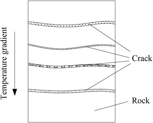
FIGURE 1. Crack distribution in rock induced by unidirectional freeze–thaw damage.
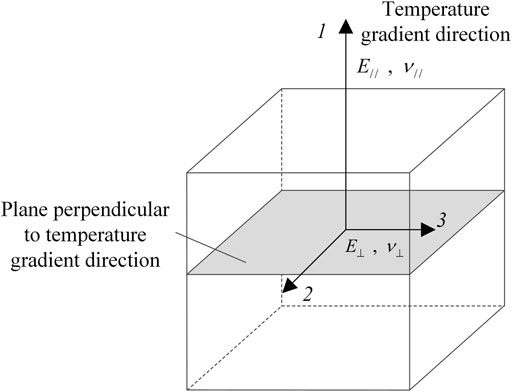
FIGURE 2. Transverse isotropy of rock induced by unidirectional freeze–thaw damage.
As illustrated in Figure 3, when the cold air in winter or the hot air in summer flows into cold region tunnels, heat mainly transfers along the radial direction with a prime temperature gradient in the radial direction, and the temperature gradient along the circumferential or axial direction is negligible (Lai et al., 2002; Zhang et al., 2002). Hence, the surrounding rock in freeze–thaw circles suffers unidirectional freeze–thaw action every year. Thus, the mechanical properties of rock in freeze–thaw circles gradually transform into transverse isotropy. As shown in Figure 4, the radial direction, namely, the temperature gradient direction, is the axis of transverse isotropy, and the cylindrical surface composed of the axial direction and circumferential direction, which is perpendicular to the radial direction, is the plane of isotropy.
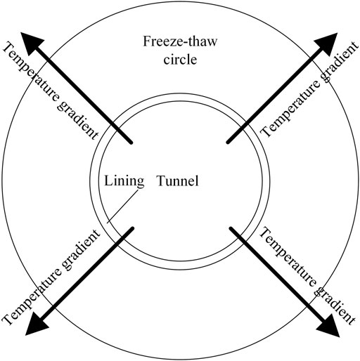
FIGURE 3. Temperature gradient in cold region tunnels.
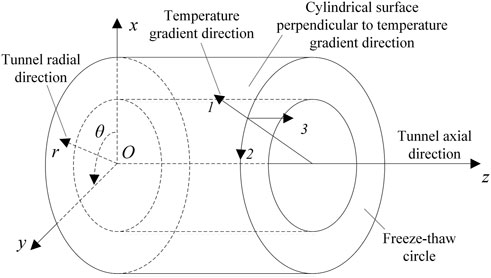
FIGURE 4. Transverse isotropy of freeze–thaw circle in cold region tunnels.
Figure 5 illustrates the mechanical model of the stress and deformation response of cold region tunnels with transversely isotropic rock in freeze–thaw circles induced by unidirectional freeze–thaw damage. As displayed in Figure 5, in the initial state, when the construction of the tunnel completes, the surrounding rock is isotropic; after entering the cold season, the surrounding rock in the freeze–thaw circle freezes gradually, and, thus, the freeze–thaw circle is isotropic and frozen, which can be referred to as state F. During the operation of the tunnel, the surrounding rock in the freeze–thaw circle gradually transform into transversely isotropic material due to the unidirectional freeze–thaw damage. The stress and displacement in cold region tunnels will significantly change with the transformation of the freeze–thaw circle from isotropic material to transversely isotropic material. In the warm season, the freeze–thaw circle is transversely isotropic and unfrozen, which can be referred to as state TU; in the cold season, the freeze–thaw circle is transversely isotropic and frozen, which can be referred to as state TF, as shown in Figure 5. In Figure 5, zone I is the lining, and zone V is isotropic and unfrozen surrounding rock. Zone II is the isotropic and frozen surrounding rock in state F; zone III is the transversely isotropic and unfrozen surrounding rock in state TU; and zone IV is the transversely isotropic and frozen surrounding rock in state TF.
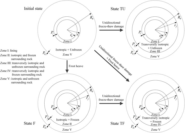
FIGURE 5. Mechanical model of cold region tunnels.
Moreover, in Figure 5,
The compressive stress, strain, and displacement are regarded as positive. To obtain the analytical solution of mechanical response under a transversely isotropic freeze–thaw circle, assumptions are introduced as follows:
(1) The cross-section of cold region tunnels is approximated as a circle.
(2) The plane strain condition is introduced.
(3) The surrounding rock and lining are considered as continuous, homogeneous, and elastic materials in each zone.
(4) The lining and the surrounding rock in zones II and V are isotropic material, whereas the surrounding rock in zones III and IV are transversely isotropic material induced by the unidirectional freeze–thaw damage.
The constitutive relations of a transversely isotropic freeze–thaw circle in zone III can be written as (Lekhnitskii, 1981) follows:
where
Under the plane strain condition,
Substituting Eq. 2 into Eq. 1,
where
According to the elasticity, the geometric equations and the compatibility condition of the axisymmetric problem are as follows:
where
Moreover, the equilibrium equation of the axisymmetric problem is
Combining Eqs 3, 4b, and 5, the following equation can be acquired:
The general solution of Eq. 6 is
where
The stress boundary conditions of zone III are:
where the superscript III represents zone III. In addition, the following superscripts I, II, IV, and V represent zones I, II, IV, and V, respectively.
Considering Eqs 7 and 8,
Combining Eqs 9, 7, and 5,
Plugging Eqs 1–3,
Plugging Eq. 11 to Eq. 4a,
According to the solution upon axisymmetric problem (Yu, 2000), the displacement and stress in isotropic and unfrozen zone V under the action of
where
In addition, according to the solution upon axisymmetric problem (Yu, 2000), the displacement and stress in lining (zone I) under the action of
where
The continuity conditions of displacement at interfaces
The undetermined quantities are
where
Finally, substituting the value of
In the frozen zone IV, the total strain of surrounding rock consists of the strain resulting from local stress and the frost heaving strain. Therefore, the constitutive relations of the transversely isotropic and frozen rock in the freeze–thaw circle in zone IV are as follows:
where
where
Under the plane strain condition,
Substituting Eq. 21 into Eq. 19,
where
Combining Eqs 22, 4b, and 5, the following equation can be acquired:
The general solution of Eq. 23 can be obtained as follows:
where
The stress boundary conditions of zone IV are
Plugging Eq. 24 into Eq. 25,
Combining Eqs 26, 24, and 5,
Substituting Eqs 27 and 24 into Eq. 22,
The continuity conditions of displacement at interfaces
The stress and displacement in isotropic and unfrozen zone V and lining (zone I) under state TF are the same as those given in Eqs 13–16, except that
where
Finally, substituting the value of
To analyze the effect of transversely isotropic rock in freeze–thaw circles on the mechanical response of cold region tunnels, comparisons among the initial state, state F, state TU, and state TF are necessary. Hence, the solutions of stress and displacement in cold region tunnels under initial state and state F are also provided here.
The stress and displacement in the lining (zone I) under the initial state are the same as those given in Eqs 15 and 16, except that
The displacement continuity conditions at interface
The undetermined quantity is
Finally, substituting the value of
Furthermore, the stress and displacement of isotropic and unfrozen zone V and lining (zone I) under state F are the same as those given in Eqs 13–16, except that
The proposed analytical solutions of stress and displacement under states TU and TF are extensions of the stress analysis on cold region tunnels involving transversely isotropic rock in freeze–thaw circle induced by unidirectional freeze–thaw damage. The engineering case in the study by Lv et al. (2019) can be referred to analyze the effect of a transversely isotropic freeze–thaw circles on the mechanical response of cold region tunnels. The related parameters are presented in Table 1, and
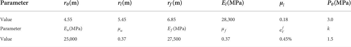
TABLE 1. Parameters of the section K105+785 in the cold region tunnel.
During the operation stage of the cold region tunnel, the surrounding rock in the freeze–thaw circle gradually transforms to the transversely isotropic material resulting from unidirectional freeze–thaw damage, and
Under the initial state, the radial stress act on the lining
Under state F,
To study the mechanical response of cold region tunnels under a transversely isotropic freeze–thaw circle, the stress distribution in lining and surrounding rock in the case that
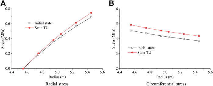
FIGURE 6. Stress of lining under initial state and state TU.
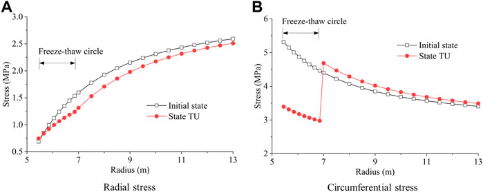
FIGURE 7. Stress of surrounding rock under initial state and state TU.

FIGURE 8. Stress of lining under state F and state TF.
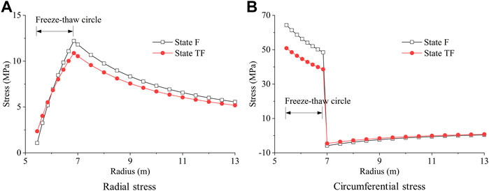
FIGURE 9. Stress of surrounding rock under state F and state TF.
The surrounding rock is unfrozen under the initial state and state TU. The stress distribution in the lining is similar under these two states, whereas the radial and circumferential stress in the lining increase by about 8% when the surrounding rock in the freeze–thaw circle transforms from isotropic material into transversely isotropic material, as displayed in Figure 6. In addition, the radial stress in surrounding rock under state TU is gently less than that under the initial state, and the greatest difference occurs at the outer interface of the freeze–thaw circle, as displayed in Figure 7. Phenomenon of discontinuity generates in the circumferential stress of surrounding rock under state TU, and the circumferential stress in the freeze–thaw circle under state TU is significantly less than that under the initial state.
The surrounding rock in the freeze–thaw circle is frozen under states F and TF. The stress in the lining under state TF significantly increases to be greater than two times of that under state F when the surrounding rock in the freeze–thaw circle transforms from isotropic material into transversely isotropic material, as illustrated in Figure 8. For example, the radial stress at the outer interface of the lining is 1.07 MPa under state F, while it increases to 2.35 MPa under state TF. Moreover, the difference of radial stress in surrounding rock under states F and TF is slight, and the circumferential stress in the freeze–thaw circle under state TF is less than that under state F, as illustrated in Figure 9.
Therefore, the transformation of surrounding rock in the freeze–thaw circle from isotropic material into transversely isotropic material adversely affects the stress distribution in the lining, especially for state TF, under which the stress in the lining increases significantly. Hence, the influence of the transversely isotropic freeze–thaw circle should be considered to maintain the long-term stability of cold region tunnels.
The abovementioned engineering case can be considered to research the effect of the deterioration coefficient
Figures 10 and 11 show the influence of the deterioration coefficient
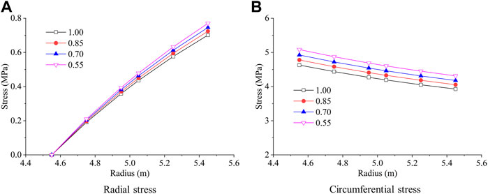
FIGURE 10. Influence of deterioration coefficient
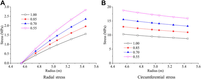
FIGURE 11. Influence of deterioration coefficient
Moreover, Figure 12 shows the variation of the pressure act on the lining

FIGURE 12. Influence of deterioration coefficient
Figures 13 and 14 show the influence of the degree of anisotropy
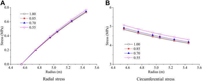
FIGURE 13. Influence of degree of anisotropy
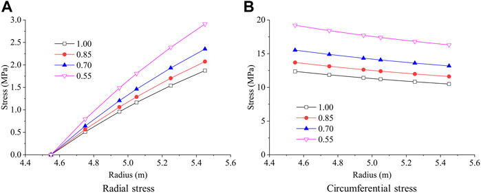
FIGURE 14. Influence of degree of anisotropy
In cold region tunnels, surrounding rock in a freeze–thaw circle suffers unidirectional freeze–thaw cycles during the operation process, and, thus, isotropic surrounding rocks gradually transform into transversely isotropic materials. Based on this phenomenon, an analytical solution to the mechanical response of cold region tunnels with a transversely isotropic freeze–thaw circle induced by unidirectional freeze–thaw damage is proposed. The analytical solution is derived under two different states of the freeze–thaw circle: 1) transversely isotropic and unfrozen state and 2) transversely isotropic and frozen state.
Additionally, the stress distribution in the lining and surrounding rock with a transversely isotropic freeze–thaw circle is analyzed. The transformation of the surrounding rock in a freeze–thaw circle from isotropic material into transversely isotropic material adversely affects the stress distribution in the lining, especially in the transversely isotropic and frozen state, under which the stress in the lining increases significantly.
Finally, the influence of the deterioration coefficient
The raw data supporting the conclusions of this article will be made available by the authors, without undue reservation.
ZL: funding acquisition, writing—original draft, and methodology. MW: data curation and validation. FH: conceptualization, writing—review and editing. YC: formal analysis and investigation.
This research was supported by the National Natural Science Foundation of China (No. 52108370) and Jiangxi Provincial Natural Science Foundation (No. 20212BAB214062).
The authors declare that the research was conducted in the absence of any commercial or financial relationships that could be construed as a potential conflict of interest.
All claims expressed in this article are solely those of the authors and do not necessarily represent those of their affiliated organizations, or those of the publisher, the editors, and the reviewers. Any product that may be evaluated in this article, or claim that may be made by its manufacturer, is not guaranteed or endorsed by the publisher.
Chang, Z., Catani, F., Huang, F., Liu, G., Meena, S., Huang, J., et al. (2022). Landslide susceptibility prediction using slope unit-based machine learning models considering the heterogeneity of conditioning factors. J. Rock Mech. Geotechnical Eng. doi:10.1016/j.jrmge.2022.07.009
Ding, S., Jia, H., Zi, F., Dong, Y., and Yao, Y. (2020). Frost damage in tight sandstone: Experimental evaluation and interpretation of damage mechanisms. Materials 13, 4617. doi:10.3390/ma13204617
Feng, Q., Fu, S., Wang, C., Liu, W., Wang, Y., and Qiao, W. (2019). Analytical elasto-plastic solution for frost force of cold-region tunnels considering anisotropic frost heave in the surrounding rock. KSCE J. Civ. Eng. 23, 3831–3842. doi:10.1007/s12205-019-1446-7
Feng, Q., Jiang, B.-S., Zhang, Q., and Wang, G. (2016). Reliability research on the 5-cm-thick insulation layer used in the Yuximolegai tunnel based on a physical model test. Cold Regions Sci. Technol. 124, 54–66. doi:10.1016/j.coldregions.2016.01.001
Feng, Q., Jiang, B.-S., Zhang, Q., and Wang, L. (2014). Analytical elasto-plastic solution for stress and deformation of surrounding rock in cold region tunnels. Cold Regions Sci. Technol. 108, 59–68. doi:10.1016/j.coldregions.2014.08.001
Feng, Q., Jin, J., Zhang, S., Liu, W., Yang, X., and Li, W. (2022). Study on a damage model and uniaxial compression simulation method of frozen-thawed rock. Rock Mech. Rock Eng. 55, 187–211. doi:10.1007/s00603-021-02645-2
Feng, Q., Liu, W., and Jiang, B.-S. (2017). Analytical solution for the stress and deformation of rock surrounding a cold-regional tunnel under unequal compression. Cold Regions Sci. Technol. 139, 1–10. doi:10.1016/j.coldregions.2017.04.003
Gao, G. Y., Chen, Q. S., Zhang, Q. S., and Chen, G. Q. (2012). Analytical elasto-plastic solution for stress and plastic zone of surrounding rock in cold region tunnels. Cold Regions Sci. Technol. 72, 50–57. doi:10.1016/j.coldregions.2011.11.007
Huang, F., Cao, Z., Jiang, S., Zhou, C., Huang, Z., and Guo, Z. (2020). Landslide susceptibility prediction based on a semi-supervised multiple-layer perceptron model. Landslides 17, 2919–2930. doi:10.1007/s10346-020-01473-9
Huang, F., Chen, J., Liu, W., Huang, J., Hong, H., and Chen, W. (2022). Regional rainfall-induced landslide hazard warning based on landslide susceptibility mapping and a critical rainfall threshold. Geomorphology 408, 108236. doi:10.1016/j.geomorph.2022.108236
Huang, F., Tao, S., Chang, Z., Huang, J., Fan, S., Jiang, L., et al. (2021). Efficient and automatic extraction of slope units based on multi-scale segmentation method for landslide assessments. Landslides 18, 3715–3731. doi:10.1007/s10346-021-01756-9
Huang, S., He, Y., Yu, S., and Cai, C. (2022a). Experimental investigation and prediction model for UCS loss of unsaturated sandstones under freeze-thaw action. Int. J. Min. Sci. Technol. 32, 41–49. doi:10.1016/j.ijmst.2021.10.012
Huang, S., Yu, S., Ye, Y., Ye, Z., and Cheng, A. (2022b). Pore structure change and physico-mechanical properties deterioration of sandstone suffering freeze-thaw actions. Constr. Build. Mater. 330, 127200. doi:10.1016/j.conbuildmat.2022.127200
Lai, Y., Hui, H., Ziwang, Z., Songyu, S., and Xuejun, X. (2000). Analytical viscoelastic solution for frost force in cold-region tunnels. Cold Regions Sci. Technol. 31, 227–234. doi:10.1016/S0165-232X(00)00017-3
Lai, Y., Liu, S., Wu, Z., and Yu, W. (2002). Approximate analytical solution for temperature fields in cold regions circular tunnels. Cold Regions Sci. Technol. 34, 43–49. doi:10.1016/S0165-232X(01)00050-7
Li, S., Niu, F., Lai, Y., Pei, W., and Yu, W. (2017). Optimal design of thermal insulation layer of a tunnel in permafrost regions based on coupled heat-water simulation. Appl. Therm. Eng. 110, 1264–1273. doi:10.1016/j.applthermaleng.2016.09.033
Li, W., Wu, Y., Fu, H., and Zhang, J. (2015). Long-term continuous in-situ monitoring of tunnel lining surface temperature in cold region and its application. Ijht 33, 39–44. doi:10.18280/ijht.330206
Li, Y., Sun, Y., Qiu, J., Liu, T., Yang, L., and She, H. (2020). Moisture absorption characteristics and thermal insulation performance of thermal insulation materials for cold region tunnels. Constr. Build. Mater. 237, 117765. doi:10.1016/j.conbuildmat.2019.117765
Liu, H., Yuan, X., and Xie, T. (2019). A damage model for frost heaving pressure in circular rock tunnel under freezing-thawing cycles. Tunn. Undergr. Space Technol. 83, 401–408. doi:10.1016/j.tust.2018.10.012
Liu, L., Li, Z., Liu, X., and Li, Y. (2018a). Frost front research of a cold-region tunnel considering ventilation based on a physical model test. Tunn. Undergr. Space Technol. 77, 261–279. doi:10.1016/j.tust.2018.04.011
Liu, W., Feng, Q., Fu, S., and Wang, C. (2018b). Elasto-plastic solution for cold-regional tunnels considering the compound effect of non-uniform frost heave, supporting strength and supporting time. Tunn. Undergr. Space Technol. 82, 293–302. doi:10.1016/j.tust.2018.08.054
Liu, Y., Cai, Y., Huang, S., Guo, Y., and Liu, G. (2020). Effect of water saturation on uniaxial compressive strength and damage degree of clay-bearing sandstone under freeze-thaw. Bull. Eng. Geol. Environ. 79, 2021–2036. doi:10.1007/s10064-019-01686-w
Lv, Z., Xia, C., Wang, Y., and Luo, J. (2019). Analytical elasto-plastic solution of frost heaving force in cold region tunnels considering transversely isotropic frost heave of surrounding rock. Cold Regions Sci. Technol. 163, 87–97. doi:10.1016/j.coldregions.2019.04.008
Meng, X., Zhang, H., and Liu, X. (2021). Rock damage constitutive model based on the modified logistic equation under freeze–thaw and load conditions. J. Cold Reg. Eng. 35, 04021016. doi:10.1061/(ASCE)CR.1943-5495.0000268
Murton, J. B., Ozouf, J.-C., and Peterson, R. (2016). Heave, settlement and fracture of chalk during physical modelling experiments with temperature cycling above and below 0°C. Geomorphology 270, 71–87. doi:10.1016/j.geomorph.2016.07.016
Nakamura, D., Goto, T., Ito, Y., Suzuki, T., and Yamashita, S. (2009). “A basic study on frost susceptibility of rock: Differences between frost susceptibility of rock and soil,” in Proceeding of 14th conference on cold regions engineering (Duluth, Minnesota: ASCE), doi:10.1061/41072(359)11
Nakamura, D., Goto, T., Suzuki, T., Ito, Y., Yamashita, S., Kawaguchi, T., et al. (2012). “Basic study on the frost heave pressure of rocks: Dependence of the location of frost heave on the strength of the rock,” in Cold regions engineering 2012: Sustainable infrastructure development in a changing cold environment (Quebec City, Canada: American Society of Civil Engineers), 124–133. doi:10.1061/9780784412473.013
Tan, X., Chen, W., Yang, D., Dai, Y., Wu, G., Yang, J., et al. (2014). Study on the influence of airflow on the temperature of the surrounding rock in a cold region tunnel and its application to insulation layer design. Appl. Therm. Eng. 67, 320–334. doi:10.1016/j.applthermaleng.2014.03.016
Xia, C., Lv, Z., Li, Q., Huang, J., and Bai, X. (2018). Transversely isotropic frost heave of saturated rock under unidirectional freezing condition and induced frost heaving force in cold region tunnels. Cold Regions Sci. Technol. 152, 48–58. doi:10.1016/j.coldregions.2018.04.011
Yu, H. (2000). Cavity expansion methods in geomechanics. Berlin, Heidelberg: Springer Science+Business Media.
Yu, W., Lu, Y., Han, F., Liu, Y., and Zhang, X. (2018). Dynamic process of the thermal regime of a permafrost tunnel on Tibetan Plateau. Tunn. Undergr. Space Technol. 71, 159–165. doi:10.1016/j.tust.2017.08.021
Yuanming, Y., Xuefu, X., Wenbing, W., Shujuan, S., Zhiqiang, Z., and Jianzhang, J. (2005). Three-dimensional nonlinear analysis for the coupled problem of the heat transfer of the surrounding rock and the heat convection between the air and the surrounding rock in cold-region tunnel. Tunn. Undergr. Space Technol. 20, 323–332. doi:10.1016/j.tust.2004.12.004
Zeng, Y., Liu, K., Zhou, X., and Fan, L. (2017). Tunnel temperature fields analysis under the couple effect of convection-conduction in cold regions. Appl. Therm. Eng. 120, 378–392. doi:10.1016/j.applthermaleng.2017.03.143
Zhang, G., Liu, S., Zhao, X., Ye, M., Chen, R., Zhang, H., et al. (2017). The coupling effect of ventilation and groundwater flow on the thermal performance of tunnel lining GHEs. Appl. Therm. Eng. 112, 595–605. doi:10.1016/j.applthermaleng.2016.10.120
Zhang, G., Xia, C., Zhao, X., and Zhou, S. (2016). Effect of ventilation on the thermal performance of tunnel lining GHEs. Appl. Therm. Eng. 93, 416–424. doi:10.1016/j.applthermaleng.2015.10.008
Zhang, X., Lai, Y., Yu, W., and Zhang, S. (2002). Non-linear analysis for the freezing-thawing situation of the rock surrounding the tunnel in cold regions under the conditions of different construction seasons, initial temperatures and insulations. Tunn. Undergr. Space Technol. 17, 315–325. doi:10.1016/S0886-7798(02)00030-5
Zhang, X., Zhou, Z., Li, J., Zhou, Y., and Han, F. (2018). A physical model experiment for investigating into temperature redistribution in surrounding rock of permafrost tunnel. Cold Regions Sci. Technol. 151, 47–52. doi:10.1016/j.coldregions.2018.03.007
Keywords: stress distribution, cold region tunnels, transversely isotropic freeze–thaw circle, mechanical response, unidirectional freeze–thaw
Citation: Lv Z, Wu M, Huang F and Cai Y (2022) Analytical solution of mechanical response in cold region tunnels under transversely isotropic freeze–thaw circle induced by unidirectional freeze–thaw damage. Front. Earth Sci. 10:1016605. doi: 10.3389/feart.2022.1016605
Received: 11 August 2022; Accepted: 25 August 2022;
Published: 20 September 2022.
Edited by:
Guang-Liang Feng, Chinese Academy of Sciences (CAS), ChinaReviewed by:
Guozhu Zhang, Southeast University, ChinaCopyright © 2022 Lv, Wu, Huang and Cai. This is an open-access article distributed under the terms of the Creative Commons Attribution License (CC BY). The use, distribution or reproduction in other forums is permitted, provided the original author(s) and the copyright owner(s) are credited and that the original publication in this journal is cited, in accordance with accepted academic practice. No use, distribution or reproduction is permitted which does not comply with these terms.
*Correspondence: Faming Huang, ZmFtaW5naHVhbmdAbmN1LmVkdS5jbg==
Disclaimer: All claims expressed in this article are solely those of the authors and do not necessarily represent those of their affiliated organizations, or those of the publisher, the editors and the reviewers. Any product that may be evaluated in this article or claim that may be made by its manufacturer is not guaranteed or endorsed by the publisher.
Research integrity at Frontiers
Learn more about the work of our research integrity team to safeguard the quality of each article we publish.