 Qun-yi Wang
 Lin Shang
95% of researchers rate our articles as excellent or good
Learn more about the work of our research integrity team to safeguard the quality of each article we publish.
Find out more
METHODS article
Front. Earth Sci. , 05 January 2023
Sec. Structural Geology and Tectonics
Volume 10 - 2022 | https://doi.org/10.3389/feart.2022.1002676
This article is part of the Research Topic Unconventional Reservoir Geomechanics View all 16 articles
The appropriate design of the operating pressure of underground gas storages (UGSs) is of great significance to their safe and profitable operation. In situ stress is basic data for determining the upper limit pressure of UGSs, analyzing fault stability in reservoir areas, and evaluating trap tightness. Generally, the design of the upper limit gas injection pressure of UGSs is a comprehensive geomechanical problem. After research and comparison of measurement methods, it is believed that the measurement of in situ stress induced by hydraulic fracturing can accurately obtain the in situ stress value near the wellbore, and having knowledge about the reservoir stress path will considerably decrease the risk of reservoir and cap rock instability during gas injection and production. Taking Well C1, an oil reservoir-type UGS in Block M, eastern China as an example, this paper introduces the use of hydraulic fracturing (HF) in situ stress testing technology to obtain the minimum principal stress values of the caprock, reservoir and floor intervals of Well C1. The measured minimum principal stress of the caprock is 32.8–36.8 MPa. Because it is an old well, the minimum principal stress of the reservoir is 33.7–34.2 MPa after correction of the in situ stress measurement according to the theory of elasticity. Based on the comprehensive analysis of the measured in situ stress data, it is believed that the safe upper limit of the reservoir-type gas storage in Block M is 27.2 MPa.
Confirmed by research findings, natural gas will become the most demanded fossil fuel in the world in the future, and its production will reach its maximum in 2060 (Zou et al., 2018). Underground gas storage (UGS) is an important and inseparable part of the upstream and downstream of the natural gas industry. With the rapid development of China’s natural gas industry, the demand for UGSs will become increasingly urgent. China’s UGS construction began in 1999, and 26 UGSs have been built in China after 20 years, with a designed storage capacity of 41.5 billion square and working gas volume of 180 billion square (Ding et al., 2010). There are contradictions between the geological storage sites and the natural gas demand market in China. Gas fields are mainly located in central and western China, and demand markets are located in the central and eastern regions, while the oil-bearing basins in the east are dominated by oil reservoirs. Therefore, the use of oil reservoirs to build UGSs has gradually developed in China (Jiang et al., 2021).
During a high rate of multicycle operation of underground gas storage, high-flow gas is injected, and high-flow gas is produced in the short term, which brings about a force change in the fault block trap and affects the dynamic sealing integrity and is completely different from conventional oil and gas reservoir development methods. The underground gas storages that are converted form oil reservoirs and are different from gas reservoirs. The process of building UGSs is a high-speed interactive displacement process of gas, oil and water, and the three-phase seepage mechanism, spatial production characteristics and capacity expansion laws are complex. For gas storage, the purpose is to maintain the maximum gas in the reservoir without escaping it. In geological storage, gas can be stored by several physical and chemical trapping mechanisms (Benson and Cole, 2008; Gunter et al., 2004). Physical storage involves storing injected gas in structural traps and storing it as residual gas in the pore volume. As a result, geomechanical considerations have a vital impact on the short- and long-term performance of gas injection.
With gas injection and production, the pore pressure and in situ stress are altered in the different stages of UGS life (Ferretti, 2005; Vasco et al., 2001; Zhou and Burbey, 2014). The fatigue effect caused by multicycle injection-withdrawal changed the pore-throat and microcrack structures of the caprock and enhanced the sealing capacity at the in situ effective stress. The dynamic breakthrough pressure is lower than the caprock fracture pressure, so capillary sealing failure is more likely than mechanical failure (Zhu et al.). Gas injection increases the reservoir pore pressure and decreases the integrity of faults close to gas well locations (Rutqvist et al., 2014). The probability of fault reactivation is soared up because of enhancing the pore pressure. This reactivation can be monitored by parameters such as friction, cohesion, and orientation of the fault (Scholz, 2019). Thus, variations in stresses applied to the reservoir can potentially threaten the integrity of the reservoir. Additionally, the activation of faults might increase the permeability of the reservoir’s unsuitable sections. The faults and traps near the wellbore have the weakest sealing ability, so it is important to evaluate their sealing performance in the scheme design.
The appropriate design of the operating pressure of UGSs is of great significance to the safe and profitable operation of UGSs. In situ stress is basic data for determining the upper limit pressure of UGSs, analyzing fault stability in reservoir areas, and evaluating trap tightness. Generally, the design of the upper limit gas injection pressure of UGSs is a comprehensive geomechanical problem. After research and comparison of measurement methods, it is believed that the measurement of in situ stress induced by hydraulic fracturing can accurately obtain the in situ stress value near the wellbore, and having knowledge about the reservoir stress path will considerably decrease the risk of reservoir and cap rock instability during gas injection and production.
This paper introduces the use of hydraulic fracturing (HF) in situ stress testing technology to obtain the minimum principal stress values of the caprock. Example taken from the C1 Well M Block, Nanpu Sag. We combine the imaging and dipole acoustic logging data of nearby wells, the horizontal maximum principal stress and its direction are estimated, and the upper limit pressure of the M gas storage is determined.
According to the requirement of the in situ stress test for UGS construction, well C1 of UGS A is selected as the test well. The porosity of gas storage reservoir A is 27.1%, and the permeability is 619.9 mD. The temperature of the oil reservoir in the gas storage is 85 °C, the original formation pressure is 22.53 MPa, the current formation pressure coefficient is approximately 0.6, and the formation pressure is approximately 13.5 MPa. Well C1 is located at the higher part of the M fault block, with an artificial bottom of 2923 m, a vertical depth of 2341 m and a maximum well deviation of 44.66°. Based on the cementing quality, casing collar and original perforation section of the well, the in situ stress test section is determined as shown in Table 1.
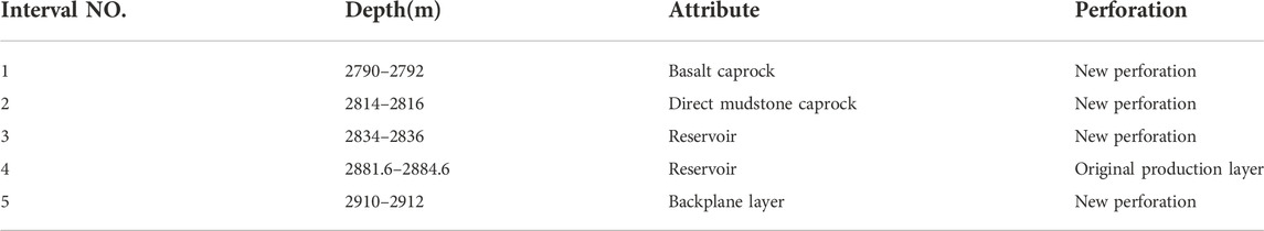
TABLE 1. Test information of the C1 well used for hydraulic fracturing.
The principle of in situ stress measurement of hydraulic fracturing is based on elastic mechanics. According to the closure pressure of the fracturing fracture, a relatively reliable minimum principal stress can be obtained. For near-vertical wells, a relatively reliable horizontal minimum principal stress can be obtained.
Different from generalized in situ stress testing methods such as small-scale fracturing testing technology in the field of oil and gas fields, the classical hydraulic fracturing in situ stress testing method uses hydraulic expansion type bridging packers or bridge plugs + packers to separate the test section. It is sealed to realize the continuous measurement of small flow in the caprock. The purpose of the small flow is to minimize the influence of pore elasticity on the measurement results without forming a complex network of fractures, and the pressure in the pressure fractures can quickly reach equilibrium after the pump is turned off. The minimum principal stress is determined by the fracture closure pressure on the fracturing curve, which has the characteristics of repeatable measurement results.
The test plan is formulated according to the characteristics of the reservoir. The sequence of preparations before the test is perforation, scraping, lowering the bridge plug, lowering the in situ stress test string, etc. A schematic diagram of the hydraulic fracturing stress measurement system is shown in Figure 1. The specific steps of the in situ stress test are as follows: 1) the pipe string is kept still, and the change in the suspension weight of the pipe string is observed during the in situ stress test. During the pressurization process, due to the pressure sensor installed in the high-pressure circuit, the pressure value on the digital acquisition instrument and the pressure gauge will increase rapidly with the pumping of the high-pressure liquid. Under the action of ground stress and pore pressure, according to the drilling cycle and the principle of stress concentration, when the pressure reaches the critical condition of tangential stress failure of the rock, the rock mass on the hole wall will rupture, and the maximum pressure value Pb recorded at this time is the rupture pressure. 2) After the rock cracks, turn off the high-pressure pump and stop injecting into the test section. After the pump is turned off, the pressure drops; after that, the pressure slowly drops as the liquid is lost to the formation. Under the action of in situ stress, the cracks tend to close. The pressure recorded when the fracture is in a critical closed state is the closure pressure Ps, which is the minimum principal stress that needs to be obtained in this test. 3) When the pressure in the fracturing section becomes stable or no longer drops significantly, the pressure in the isolation section can be released, the pressure at the wellhead can be released, and the current test can be completed. 4) After the surface pressure drops to zero, the wellhead return valve is closed, the high-pressure pump is restarted, high-pressure fluid is injected into the test section to reopen the fractures that have occurred in the rock body, and then the pump is turned off to record the closure pressure of the fractures. The above process was repeated 3–4 times to obtain a reliable minimum principal stress. 5) For ultralow permeability formations, when the pump is stopped after rupture or retension, when the surface pressure does not drop, auxiliary backflow measures can be used to speed up the fracture closure process to obtain the fracture closure pressure, that is, the minimum principal stress. Whether to adopt auxiliary backflow measures is determined by the on-site engineer according to the pressure drop curve. This on-site test uses a small flow injection test, so no auxiliary return measures are used. 6) Lift the pipe string directly for 2 m, stabilize for 15 min, unpack the packer, and pull out the test string. The abovementioned in situ stress testing process is repeated, and in situ stress testing of other layers is performed in sequence.
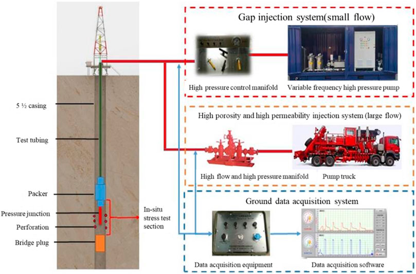
FIGURE 1. Schematic diagram of the hydraulic fracturing stress measurement system.
From the pressure–time record curve, the fracture pressure (Pb) of the rock, the instantaneous closure pressure (Ps) and the estimated fracture retension pressure (Pr) can be directly obtained. According to the above parameters, the minimum principal stress can be determined, the maximum principal stress can be estimated, and the interpretation of specific characteristic pressure parameters and the calculation method is as follows:
Fracturing pressure (Pb). The fracturing pressure (Pb) is generally easy to determine; that is, the peak pressure of the first cycle during the fracturing process is called the fracturing pressure of the rock. The fractures are connected, and the fracture pressure is generally not obvious.
Retension pressure (Pr). The retension pressure (Pr) is the pressure when the rock mass in the fracturing section is broken, and the pressure is reopened to reopen the existing fractures. Usually, the corresponding point on the pressure–time curve when the slope changes significantly is the pressure value of rupture reopening.
Close the pressure (Ps). The determination of the shut-off pressure Ps is very important for hydraulic fracturing stress measurement. The closure pressure Ps is equal to the minimum principal stress or the horizontal minimum principal stress σh, and the more commonly used and popular methods for the value of Ps include the inflection point method, single tangent and double tangent method, dt/dp method, dp/dt method, Mauskat method, flow-pressure method, G-function method, etc.
Pore pressure (Po). The formation pore pressure Po is obtained from the measured data after the oil production well is shut in to restore the formation pressure.
According to the pressure–time curve recorded by the downhole pressure gauge, combined with the flow data recorded on the surface, the pressure–time-flow and cumulative flow curves of Well C1 are drawn as shown in Figure 2, and the abovementioned method for determining the closure pressure of fracturing fractures is adopted, using the single tangent method, dP/dT method, Muskat method and G-Function method to obtain the minimum principal stress in the first round of 2790–2792 m. The calculation results are shown in Figure 3, Figure 4, Figure 5, and Figure 6, and the average value of the value results is used as the final minimum principal stress. Table 2 is a summary table of the data processing results for the direct mudstone caprock (2790–2792 m).
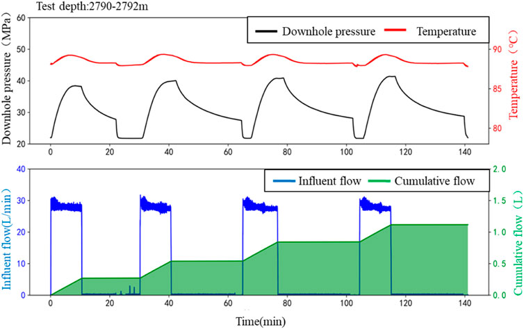
FIGURE 2. Downhole pressure–time and surface flow and cumulative flow curves.
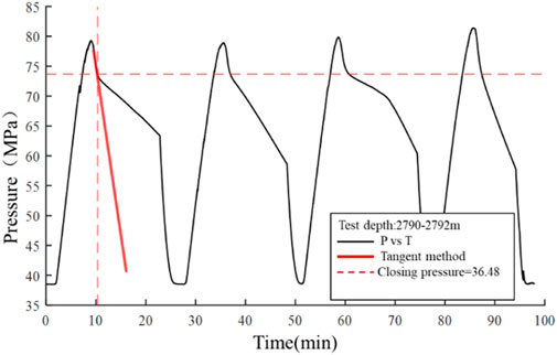
FIGURE 3. Calculation of the 1st minimum principal stress by the single tangent method.
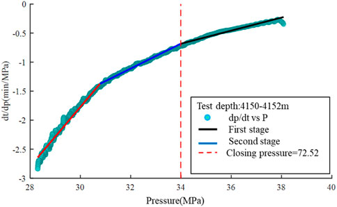
FIGURE 4. Calculation of the 1st minimum principal stress by the dp/dt method.
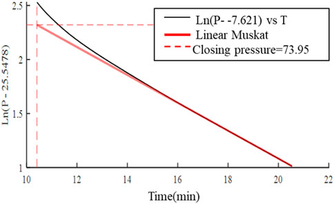
FIGURE 5. Calculation of the 1st minimum principal stress by the Muskat method.
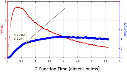
FIGURE 6. Calculation of the 1st minimum principal stress by the G-function method.
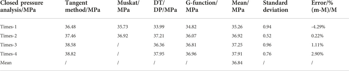
TABLE 2. Summary of data processing results of overlying mudstone caprock (2790–2792 m).
Using hydraulic fracturing in situ stress test technology, the in situ minimum main stress of the five test intervals within the depth range of 2790–2912 m (vertical depth 2244.8–2331.5 m) of reservoir-type gas storage well C1 in Block M was obtained. The in situ stress measurement results of the five layers from top to bottom are shown in Table 3. The measured results show that the minimum principal stress value of the overlying mudstone caprock is the highest.
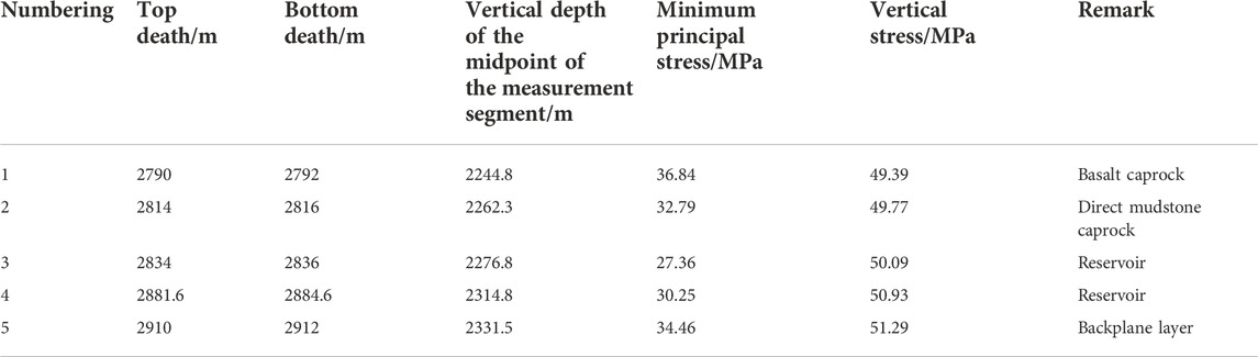
TABLE 3. Summary of the measurement results of in situ stress caused by hydraulic fracturing in Well C1.
1) In situ stress measurement results after pore pressure correction
The test hole of Well C1 is an old well. After years of production, the formation pressure coefficient (pore pressure) of the reservoir drops significantly. According to the theory of poroelasticity, a decrease in formation pore pressure will lead to a decrease in stress in the reservoir. For transversely isotropic reservoirs, the relationship between the variation in the horizontal minimum principal stress and the variation in pore pressure is:
where ΔSh is the minimum principal stress change, ΔPp is the pore pressure change, α is the Biot coefficient, which is 1, and ν is Poisson’s ratio, which is 0.2 in the calculation.
The Biot coefficient of the reservoir in Well C1 are approximately 0.6 and 0.8. During the operation of the gas storage, during the gas injection cycle, the pore pressure in the reservoir increases, which will cause the minimum principal stress in the reservoir to increase. When the formation pressure of the reservoir increases when the coefficient rises to 1.0, the corrected results of the minimum principal stress in the reservoir are shown in Table 4.
2) Evaluation of the ultimate bearing capacity of the caprock
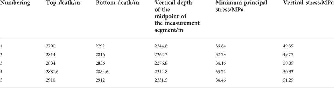
TABLE 4. In situ stress measurement results after pore pressure correction.
The ultimate pressure evaluation based on the mechanical integrity of the caprock mainly includes two aspects: tensile failure and shear failure resistance. My country has not officially published the national standard for determining the upper limit pressure of gas storage. Referring to the method for determining the upper limit pressure of gas storage in Canada, the upper limit pressure of gas storage = minimum principal stress of formation × 0.8.
1) Critical fluid pressure for caprock tensile failure
For the tensile failure capacity of the caprock, the critical formation fluid pressure should be greater than the sum of the horizontal minimum principal stress σh and the tensile strength T. Based on the above measured results of the in situ stress, the minimum horizontal principal stress at the interface of the reservoir cap rock of gas storage M is calculated to be 34.2 MPa. The European Union, Canada, Australia and other national gas storage standards stipulate that the maximum gas injection pressure must be less than 80% of the minimum principal stress. According to this method, the maximum safe gas injection pressure of the caprock is calculated as 27.2.
2) Critical fluid pressure for caprock shear failure
The shear failure risk assessment of caprock is based on the experimental study of rock mechanics, and based on the rock shear failure criterion (such as the Mohr–Coulomb criterion), the shear failure index is calculated, and the risk quantitative evaluation is realized. At present, the most classic method for evaluating the risk of caprock shear failure is based on the Mohr–Coulomb criterion in rock mechanics. Based on this criterion, the caprock safety factor is calculated by the following formula:
where:
It can be seen from the above formula that the maximum and minimum effective principal stresses are the main factors affecting the risk of shear failure of the caprock, which are closely related to th Mohr–Coulomb e change in formation pressure. The three-dimensional in situ stress field of the trap before the construction of the gas reservoir is inverted according to the mine field test and the numerical simulation of geomechanics. If the local maximum and minimum effective principal stresses of the caprock are quite different, the shear safety index calculated by the above formula is very small or even close to 0, indicating that a certain shear failure has occurred in the caprock before the construction of the library. In the experimental test, the average compressive strength of the caprock under the net overlying confining pressure is as high as 304.1 MPa, and the shear strength is 136.6 MPa, which is much higher than the current three-dimensional in situ stress. Based on the effective stress theory, the calculation formula of the maximum ultimate bearing pressure is as follows:
Considering the critical fluid pressure of the caprock tensile failure and shear failure, the ultimate pressure bearing capacity of the caprock is considered to be 38.3 MPa, and after considering the 80% safety factor, the safe pressure bearing capacity is 30.6 MPa.
3) Design of upper limit pressure of UGSs
According to the dynamic sealing evaluation results of the gas storage geological body of gas storage M, from the perspective of the static and dynamic ultimate pressures of the caprock, the ultimate pressure bearing capacity of the oil reservoir is comprehensively evaluated to be 27.2 MPa, and the main controlling factors are fault slip and lateral closure, as shown in Table 5.
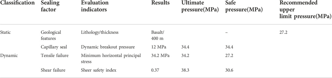
TABLE 5. M UGS geological body pressure bearing capacity evaluation table.
The evaluation of the ultimate pressure bearing capacity of the gas storage geological body in the construction of oil and gas storage gas storage is a key issue in the design of the upper limit pressure of the gas storage operation. The main evaluation objects include caprocks and faults. For the conversion of oil and gas reservoirs to gas storage, the most basic requirement for the ultimate pressure bearing capacity of gas storage geological bodies is to ensure that the caprocks and faults do not undergo macroscopic rupture and slippage and to optimize the design for the upper limit pressure of the gas storage operation and the dynamic monitoring system.
This paper introduces in detail the equipment, procedures and data processing of in situ stress measurements using hydraulic fracturing technology. The test interval has high reliability, each interval has at least three measurements, and the fracture closure pressure of different test times has high consistency. The relative error of each measurement interval is less than 5%, and the test results of the hydraulic fracturing in situ stress measurement method have high accuracy and are basically consistent with the interpretation results of in situ stress in this area, which can meet the evaluation requirements of the ultimate pressure-bearing capacity of the geological body of underground gas storage.
Based on the measured in situ stress data, the ultimate pressure-bearing capacity of the caprock of the UGS geological body was evaluated. The comprehensive analysis concluded that the safe upper limit of the reservoir-type UGS in Block M is 27.2 MPa. There is a lack of experience and precedents for building complex fault-block reservoirs, and there are still certain uncertainties in terms of the limitations of geological understanding.(Arree et al., 2009), (CCST, 2018).
The original contributions presented in the study are included in the article/supplementary material, further inquiries can be directed to the corresponding author.
LS was responsible for the conception and design of the study, while others were responsible for analyzing and interpreting the data.
Authors QW, LS, CX, YS, GG, MW, and XG were employed by Jidong Oilfield Company, PetroChina.
All claims expressed in this article are solely those of the authors and do not necessarily represent those of their affiliated organizations, or those of the publisher, the editors and the reviewers. Any product that may be evaluated in this article, or claim that may be made by its manufacturer, is not guaranteed or endorsed by the publisher.
Anna, M., Vítězová, M., Vitez, T., Buriankova, I., Huber, H., Dengler, L., et al. (2021). Underground gas storage as a promising natural methane bioreactor and reservoir. J. Energy Storage 47, 103631. doi:10.1016/j.est.2021.103631
Arree, B., Barree, V., and Craig, D. (2009). Holistic fracture diagnostics: Consistent interpretation of prefrac injection tests using multiple analysis methods[J]. SPE Prod. operations 24 (3), 396–406. doi:10.2118/107877-PA
Bakhtiari, M., Shad, S., Zivar, D., and Razaghi, N. (2021). Coupled hydromechanical analysis of underground gas storage at Sarajeh field, Qom formation, Iran. J. Nat. Gas. Sci. Eng. 92, 103996. doi:10.1016/j.jngse.2021.103996
CCST (2018). Long term viability of underground natural gas storage in California: An independent review of scientific and technical information California council on science and technology (CCST). Sacramento, USA: CCST. AvaliableAt: http://ccst.us/projects/natural_gas_storage/publications.php.
Dehghan, A. N., Goshtasbi, K., Ahangari, K., and Jin, Y. (2016). Mechanism of fracture initiation and propagation using a tri-axial hydraulic fracturing test system in naturally fractured reservoirs. Eur. J. Environ. Civ. Eng. 20, 560–585. doi:10.1080/19648189.2015.1056384
Ding, G. (2010). Development and driving force of globle underground gas storage. Natural Gas Industry 30 (8), 59–61. doi:10.3787/j.issn.1000-0976.2010.08.016
Gilbert, G., Backé, R., Puspitasari, Z., Pallikathekathil, J., Maney, B., and Dewhurst, D. (2013). Model. geomechanics gas storage a case study Iona gas field, Aust. J. Greenh. Gas Control 13, 138–148. doi:10.1016/j.ijggc.2012.12.009
Haimson, B., and Cornet, F. (2003). ISRM suggested methods for rock stress estimation—Part 3: Hydraulic fracturing (HF) and/or hydraulic testing of pre-existing fractures (HTPF). Int. J. Rock Mech. Min. Sci. 40 (7-8), 1011–1020. doi:10.1016/j.ijrmms.2003.08.002
Jeanne, P., Zhang, Y., and Rutqvist, J. (2020). Influence of hysteretic stress path behavior on seal integrity during gas storage operation in a depleted reservoir. J. Rock Mech. Geotechnical Eng. 12, 886–899. doi:10.1016/j.jrmge.2020.06.002
Jia, S., Fu, X., and Wang, J. (2020). Trap integrity evaluation of porous underground gas storage. Science Press.
Jiang, T., Wang, J., Wang, Z., and Zhou, D. (2021). Practice and understanding of collaborative construction of underground gas storge and natural gas flooding. Nat. Gas. Ind. 41 (9), 66–74. doi:10.3787/j.issn.1000-0976.2021.09.007
Jin, Z., Yuan, Y., Sun, D., Liu, Q., and Li, S. (2014). Models for dynamic evaluation of mudstone/shale cap rocks and their applications in the Lower Paleozoic sequences, Sichuan Basin, SW China. Mar. Pet. Geol. 49, 121–128. doi:10.1016/j.marpetgeo.2013.10.001
Kano, Y., Fujii, T., Uehara, S., Honda, K., and Sorai, M. (2014). Experimental study of sealing performance: Effects of particle size and particle-packing state on threshold pressure of sintered compacts. J. Geophys. Res. Solid Earth 119, 5482–5496. doi:10.1002/2014jb011177
Lin, W., Xiong, S., Liu, Y., He, Y., and Liu, S. (2021). Spontaneous imbibition in tight porous media with different wettability: Pore-scale simulation phys. Fluids (1994) 33 (3), 032013. doi:10.1063/5.0042606
Liu, J., Ding, W., Yang, H., Wang, R., Yin, S., Li, A., et al. (2017). 3D geomechanical modeling and numerical simulation of in situ stress fields in shale reservoirs: A case study of the lower cambrian niutitang formation in the cen'gong block, south China. Tectonophysics 712, 663–683. doi:10.1016/j.tecto.2017.06.030
Liu, J., Mei, L., Ding, W., Xu, K., Yang, H., and Liu, Y. (2022b). Asymmetric propagation mechanism of hydraulic fracture networks in continental reservoirs. GSA Bull. doi:10.1130/B36358.1
Liu, J., Yang, H., Xu, K., Wang, Z., Liu, X., Cui, L., et al. (2022a). Genetic mechanism of transfer zones in rift basins: Insights from geomechanical models. GSA Bull. 134, 2436–2452. doi:10.1130/B36151.1
Lynch, T., Fisher, Q., Angus, D., and Lorinczi, P. (2013). Investigating stress path hysteresis in a CO2 injection scenario using coupled geomechanical-fluid flow modeling. Energy Procedia 37, 3833–3841. doi:10.1016/j.egypro.2013.06.280
Mahdi, D. S., Al-Khdheeawi, E. A., Yuan, Y., Zhang, Y., and Iglauer, S. (2021). Hydrogen underground storage efficiency in a heterogeneous sandstone reservoirciency in a heterogeneous sandstone reservoir. Adv. Geo-Energy Res. 5 (4), 437–443. doi:10.46690/ager.2021.04.08
Mitaim, S., and Detournay, E. (2004). Damage around a cylindrical opening in a brittle rock mass. Int. J. Rock Mech. Min. Sci. 41, 1447–1457. doi:10.1016/j.ijrmms.2004.09.009
Mou, P., Pan, J., Wang, K., Wei, J., Yang, Y., and Wang, X. (2020). Influences of hydraulic fracturing on microfractures of high-rank coal under different in-situ stress conditions. Fuel 287, 119566. doi:10.1016/j.fuel.2020.119566
Mukherjee, S., Rajabi, M., Esterle, J., and Copley, J. (2020). Subsurface fractures, in-situ stress and permeability variations in the Walloon coal measures, eastern surat basin, queensland, Australia. Int. J. Coal Geol. 222, 103449. doi:10.1016/j.coal.2020.103449
Pijnenburg, R., Hangx, S., and Spiers, C. (2019). Inelastic deformation of the slochteren sandstone: Stress-strain relations and implications for induced seismicity in the groningen gas field. J. Geophys. Res. Solid Earth 124, 5254–5282. doi:10.1029/2019JB017366
Sadeghi, S., and Sedaee, B. (2021). Mechanistic simulation of cushion gas and working gas mixing during underground natural gas storage. J. Energy Storage 46, 103885. doi:10.1016/j.est.2021.103885
Schmitt, D. R., Currie, C. A., and Zhang, L. (2012). Crustal stress determination from boreholes and rock cores: Fundamental principles. Tectonophysics 580, 1–26. doi:10.1016/j.tecto.2012.08.029
Soeder, D. J. (2021). Greenhouse gas sources and mitigation strategies from a geosciences perspective. Adv. Geo-Energy Res. 5 (3), 274–285. doi:10.46690/ager.2021.03.04
Sui, Y., Lin, T., Liu, X., Dong, C., Cheng, W., Zhang, G., et al. (2011). Numerical simulation for the effect of cyclic stress on microstructure and mechanical properties of reservoir rocks during operations of gas storage. J. China Univ. Petroleum(Edition Nat. Sci. 44 (2), 78–84. doi:10.1016/j.proeng.2011.05.040
Sun, J., Zheng, D., Wang, J., Liu, J., Shi, L., Xu, H., et al. (2018). Development trend and driving force of global underground gas storage. AvaliableAt: http://onepetro.org/SPEEURO/proceedings-pdf/18EURO/2-18EURO/D022S013R001/1209055/spe-190838-ms.pdf/1 (Accessed June 19, 2022).
Wang, B., Li, D., Xu, B., Wang, Q., Zhang, F., Wang, Q., et al. (2021). Probabilistic-based geomechanical assessment of maximum operating pressure for an underground gas storage reservoir, NW China. Geomechanics for Energy and the Environment 31, 100279. doi:10.1016/j.est.2021.100279
Wang, J., Feng, X., Wanyan, Q., Zhao, Q., Pei, Z., Zie, G., et al. (2021). Hysteresis effect of three-phase fluids in the high-intensity injectioneproduction process of sandstone underground gas storages. Energy 242. doi:10.1016/j.energy.2012.123058
Xu, K., Tian, J., Yang, H., Zhang, H., Ju, W., Liu, X., et al. (2022). Effects and practical applications of present-day in-situ stress on reservoir quality in ultra-deep layers of Kuqa Depression, Tarim Basin, China. J. Nat. Gas Geoscience 7, 85–94. doi:10.1016/j.jnggs.2022.04.002
Xu, T., Tian, H., Zhu, H., and Cai, J. (2022). China actively promotes CO2 capture, utilization and storage research to achieve carbon peak and carbon neutrality. Adv. Geo-Energy Res. 6 (1), 1–3. doi:10.46690/ager.2022.01.01
Zhang, G., Zeng, D., Fan, Z., Mi, L., Wang, D., Yang, X., et al. (2021). Method and application of in situ stress field to evaluate fault sealing of underground gas storage traps. Nat. Gas. Geosci. 32, 923–930. doi:10.11764/j.issn.1672-1926.2021.01.014
Zhu, S., Zheng, D., Sun, J. G., Wu, Z., Wang, J., Guan, C., et al. (2022). Experimental study on dynamic sealing capacity and safe threshold of caprock in underground gas storges. J. Nat. Gas. Sci. Eng. 101, 104521. doi:10.1016/j.jngse.2022.104521
Keywords: underground gas storage, hydraulic fracturing, in situ stress test, operating pressure, oil reservoirs
Citation: Wang Q-y, Shang L, Xin C-y, Sun Y-c, Gao G-l, Wang M and Gu X (2023) Application of the in-situ stress testing technology for the design of operating pressure of underground gas storage reservoir. Front. Earth Sci. 10:1002676. doi: 10.3389/feart.2022.1002676
Received: 25 July 2022; Accepted: 07 September 2022;
Published: 05 January 2023.
Edited by:
Jingshou Liu, China University of Geosciences Wuhan, ChinaReviewed by:
Jiyuan Zhang, China University of Petroleum, ChinaCopyright © 2023 Wang, Shang, Xin, Sun, Gao, Wang and Gu. This is an open-access article distributed under the terms of the Creative Commons Attribution License (CC BY). The use, distribution or reproduction in other forums is permitted, provided the original author(s) and the copyright owner(s) are credited and that the original publication in this journal is cited, in accordance with accepted academic practice. No use, distribution or reproduction is permitted which does not comply with these terms.
*Correspondence: Lin Shang, c2hhbmdsaW5zb25ueUAxNjMuY29t
Disclaimer: All claims expressed in this article are solely those of the authors and do not necessarily represent those of their affiliated organizations, or those of the publisher, the editors and the reviewers. Any product that may be evaluated in this article or claim that may be made by its manufacturer is not guaranteed or endorsed by the publisher.
Research integrity at Frontiers
Learn more about the work of our research integrity team to safeguard the quality of each article we publish.