 Hong Zhang1
 Yihan Wu
 Shiting Huang
 Lu Zheng
 Yuanbing Miao
- 1College of Civil Engineering, Tongji University, Shanghai, China
- 2College of Civil Engineering, Fuzhou University, Fuzhou, China
- 3Sichuan University-The Hong Kong Polytechnic University Institute for Disaster Management and Reconstruction, Sichuan University, Chengdu, China
Flexural toppling is one of the failure modes of anti-dip rocks, is often triggered by seismic load, occurs haphazardly under an earthquake scenario, and is characterized by high speed and extreme energy, leading to catastrophic disaster consequences and huge losses. However, there is limited literature that reveals its failure mechanisms and describes the failure surface due to earthquakes. Therefore, based on the limit equilibrium analysis method, the horizontal pseudo-static load was applied to improve the geological mechanical model under gravity only, and the stability analysis process was derived. The failure surface and failure mode of the slope under different seismic loads were analyzed. The results indicated that, with the increasing seismic load, an increase in the number of rock layers with sliding failure increased the number of rock layers with cantilever toppling failure; in contrast, the number of rock layers with overlapping toppling failure decreased. The slope toe was more prone to sliding and the slope top was more prone to cantilever toppling under an earthquake, which decreased the stability of the anti-dip rock slope.
Introduction
An anti-dip rock slope (Zuo et al., 2005) is a common geological feature worldwide, existing not only in mountainous areas, but also along engineered slopes such as highways, railways, water and hydropower stations, and mining projects. It usually experiences flexural toppling failure under the action of gravity. The corresponding toppling failure is a typical instability mode of rock slopes (Hungr et al., 2014). It has better stability than an inclined one, but is substantially more difficult to identify although the developed 3S technologies and AI algorithms (Huang, 2007; Huang et al., 2021a; Huang et al., 2021b). Its failure varies from several surface blocks toppling to large-scale toppling (Huang et al., 2017), and develops from slowly to extremely rapidly (Bobet, 1999). The failure of this type of rock slope is often triggered by seismic loads (Keefer, 1984; Keefer, 2002; Huang and Li, 2009; Xu et al., 2009). Various field investigations have indicated that the failure of anti-dip rock slopes occurs haphazardly under an earthquake scenario and is characterized by high speed and extreme energy, leading to catastrophic disaster consequences and huge losses (Xu et al., 2009; Zhao et al., 2010; Chen and Teng, 2011; Ka et al., 2011; Li et al., 2011; Huang et al., 2013a; Nonomura and Hasegawa, 2013), arousing widespread concern in society, especially since the 2008 Wenchuan earthquake.
Goodman and Bray (Goodman and Bray, 1976) summarized toppling failures of anti-dip rock slopes into three types: block toppling, flexural toppling, and block-flexural toppling. The methods used to investigate the stability of anti-dip rock slopes under seismic loads include field investigation as mentioned above, analytical solution, numerical simulation, and physical experiment.
Among them, in particular, shaking table tests, which have been proven to be an effective approach to study both the dynamic response and failure process of anti-dip rock slopes, have been extensive applied, especially with the last 10 years. Chen et al. (Chen et al., 2020) modeled block toppling by conducting a series of shaking table tests. Aydan and Amini (Aydan and Amini, 2009) investigated the effect of seismic loads on the failure of a single column and rock slopes with the potential of flexural toppling. Huang et al. (Huang et al., 2013b) modeled the failure process of the Guantan landslide induced by the Wenchuan earthquake using a shaking table test. Fan et al. (Fan et al., 2016) studied the dynamic response and failure mode of bedding and anti-dip model slopes with weak interlayers, the dip angle was gentle, 8°. Correspondingly, Li et al. (Li et al., 2017), as well as Liu et al. (Liu et al., 2021), carried out large-scale shaking table tests to study the dynamic response of steep bedding and anti-dip rock slopes, their dip angles were 60°, 65°, and 70°. Furthermore, Yang et al. (2012) and Feng et al. (2019) performed shaking table tests to investigate the dynamic response of the anti-dip slope model, considering not only the strata, but also the structural joints.
Meanwhile, numerical simulations were performed. Yagoda-Biran and Hatzor (Yagoda-Biran and Hatzor, 2013) proposed a failure mode diagram and verified it using discontinuous deformation analysis (DDA) to investigate the effect of pseudo-seismic loads on block toppling and sliding failure. Miki et al. (2010) simulated block toppling using the Niigata Chuetsu earthquake recorded by the coupled DDA-NNM method. Feng et al. (2019) performed DDA simulations to investigate block toppling under a sinusoidal wave. Zhang et al. (2015) conducted universal distinct element code (UDEC) simulations to study flexural toppling failures under strong motion records from Wenchuan, Ludian, and Minxian. Ning et al. (2019) and Liu et al. (2021) studied block-flexural toppling on anti-dip rock slopes under seismic load using UDEC and FLAC, respectively, by analyzing the failure mode process for a prototype slope of the corresponding large shaking table test.
From the view of theoretical solution, Liu and Chen (2010) adopted the concept of the transfer coefficient, and derived an analytical approach for assessing the block toppling failure of rock slopes due to earthquake, based on Goodman and Bray (Goodman and Bray, 1976). Guo et al. (2017) also proposed an analytical solution for the block toppling failure of rock slopes during an earthquake based on the limit equilibrium method. Zheng et al. (2014) presented explicit expressions for the condition that block slenderness is relatively large. Zhang et al. (2018) deduced the analytic formula of block-flexural topping failure, and investigated the effect on the failure mode and stability subjected to seismic loads.
With the implementation of the development strategy of China’s vast western regions, there have been constructions of various large-scale infrastructures, and it is urgent to systematically study the problems of slope geological disasters under complex environments or extreme conditions. However, it is not difficult to point out that quantitative studies on toppling failure under dynamic loads are seldom reported in the current literature, compared to those on bedding landslides. Therefore, in this study, a mechanical model of anti-dip rock slopes was established with a horizontal pseudo-static load acting to analyze the slope failure mechanism and explode the failure surface under different seismic loads. The findings are of great scientific and engineering significance to prevent the deformation and instability of rock slopes, formulate earthquake prevention and disaster reduction plans and emergency response measures, and safeguard the construction and operation of major infrastructure.
Analysis of the Flexural Toppling Failure Under Pseudo-Seismic Load
Geological Geometric Model
Chen et al. (2016) developed a geological geometric model of flexural toppling failure of anti-dip rock slopes under gravity (Figures 1, 2). The limit equilibrium analysis method was used to carry out a theoretical analysis of the mechanical model of the flexural toppling failure of anti-dip rock slopes. This study introduced pseudo-seismic load to it to investigate the flexural toppling failure under an earthquake scenario. The failure surface was detected using the analytical method to explore the failure modes.
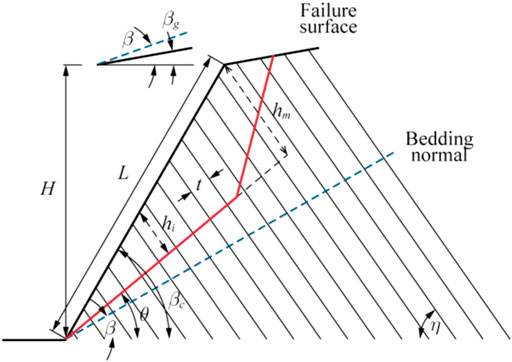
FIGURE 1. Geological model of flexural toppling failure (modified from Chen et al. (2016).
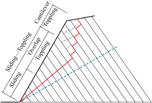
FIGURE 2. Failure mode zoning of flexural toppling (modified from Chen et al. (2016).
The intermediate parameters are defined as:
Based on the geometric relationship, the slope length is:
The rock height on the left of the failure reference plane is given as:
The rock strata were numbered from the slope toe, and the rock stratum at the top of the slope is
where int is the rounding function.
Therefore, the height of any rock on the failure surface is:
where i is the rock number,
The self-weight of any rock above the failure surface is given as:
where
Analytical Method
To simplify the mechanical analysis of flexural toppling failure in slope, the following assumptions were proposed based on the mechanism of flexural toppling failure:
1) Failure mode zoning: The rock slop failure started from the slope toe and the failure zones were divided into sliding, overlap toppling, and cantilever toppling zones.
2) Reference failure surface: The failure surface of flexural toppling failure of anti-dip rock slopes was a fold line. The boundary between the overlap and cantilever toppling zones determined the point of contra flexure; the failure was step-type above the boundary and straight line-type below the boundary.
3) When the rocks in the sliding-toppling zone failed, the interface and bottom of the adjacent rock layer met the limit friction equilibrium conditions.
4) Taking the rock strata layer as the basic element, the force on the layer was simplified as a concentrated force on point
5) The safety factor of rock layers with failure potential was equal to the safety factor of the slope.
Since the slope failure started at the slope toe, a stability analysis procedure was performed from the slope toe to the top.
First, the limit equilibrium analysis of rock strata layer #1 at the slope toe was carried out under the horizontal pseudo-static load
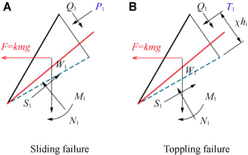
FIGURE 3. Limit equilibrium analysis of rock mass (A) Diagram of sliding failure in stratum layer; (B) Diagram of toppling failure, #1 at slope toe under horizontal pseudo-static load.
When the rock strata layer at the slope toe was analyzed according to the shear-sliding failure mode, the limit equilibrium analysis method was used to analyze the force along the failure surface. When rock strata layer #1 experienced sliding failure, the minimum force of rock strata layer #2 pushing on rock strata layer #1 is given as:
where
The rock layer at the slope toe was analyzed according to flexural toppling, and the rotating axis was at the center of the bottom surface. According to the beam-plate bending theory, the minimum force of rock strata layer #2 acts on rock strata layer #1 when rock layer #1 is toppled:
where
Then, the failure mode of rock strata layer #1 at the slope toe is:
Similarly, under the horizontal pseudo-static force, shear sliding failure occurred below rock strata layer i. As shown in Figure 4, the minimum force required from the upper rock strata layers is given as:
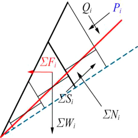
FIGURE 4. Limit equilibrium analysis of rock mass shear failure below stratum layer #i under horizontal pseudo-static load.
Flexural toppling failure occurred below rock strata layer i (Figure 5). The minimum force required from upper rock layers is:
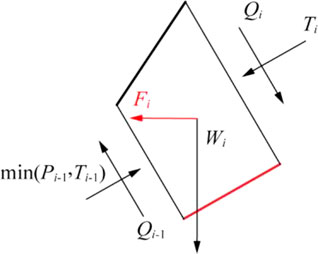
FIGURE 5. Limit equilibrium analysis of rock mass toppling failure in stratum layer #i under horizontal pseudo-static load.
It can be seen from the above two equations that when the rock strata layers nst and nst+1 failed, the rock layer nst was the boundary of the overlap toppling zone and the sliding zone, the force of the upper rock strata layers should satisfy as:
The mechanical model of the overlap toppling zone is shown in Figure 6. For the rock layer to experience flexural toppling failure, the minimum force required from the upper rock layers is:
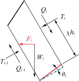
FIGURE 6. Limit equilibrium analysis of rock mass toppling failure above stratum layer #i under horizontal pseudo-static load.
The boundary of the overlap toppling zone and cantilever toppling zone (rock layer nct) is determined by the following system of inequalities:
If these inequalities are satisfied, the boundary range can be determined.
After the rock layer in the sliding zone and the cantilever toppling zone were damaged, a cantilever section appeared in the trailing edge. There was no contact between the rock layer in the cantilever toppling zone; hence, the interlayer force became zero (Figure 7). The stability analysis was converted into an “independent cantilever beam” problem. Lu et al. (Lu et al., 2012) derived the equation of critical fracture depth of a single rock layer based on the “independent cantilever beam model.” On this basis, a horizontal quasi-static force was applied in this study, as shown in Figure 7, and the critical instability length was obtained as follows:
where,
FIGURE 7. Critical instability length.
When the height of the rock layer in the cantilever toppling zone was greater than hsr, a multi-level fracture may occur. When the fracture depth of all rock layers was determined, the midpoints of the last fracture surface of each rock layer were connected to obtain the complete failure surface.
Determination of Slope Stability
An iterative calculation was carried out using Eqs. 13, 14 considering the slope toe to the slope top. The boundary of the sliding zone and the overlap toppling zone was determined using Eq. 15. Then, the force on the flexural toppling zone was obtained using Eq. 16. If Eq. 17 is satisfied, the rock layer nct is found. If Eq. 17 is not satisfied, there is no cantilever section, that is, a force is needed for the failure of each rock layer. The last rock layer needs additional external force F0 to meet the force requirements. Since this external force does not exist for the actual slope, it can be used to determine the slope stability as represented in the equation below.
where
In summary, when
Failure Surface Search
Based on the above mechanical analysis, the key parameter to determining the failure surface is to find the angle
where F is other loads on the slope.
For a given slope, except for
The cut slope surface was set as the upper searching limit, while the surface normal was the lower limit; therefore, the failure surface could be obtained based on the condition of minimum FS.
Step 1: For a given initial
Step i: Similarly, for a given value
Final step: When the angle is
Case Analysis
To verify the reliability of the method proposed in this study, the anti-dip rock slope in southern Anhui was taken as a case study. The slope model is shown in Figure 8.
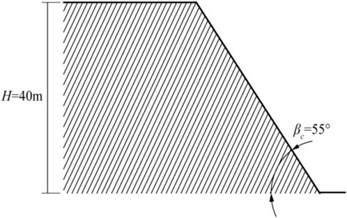
FIGURE 8. Geometric description of the anti-dip rock slope model in southern Anhui.
The slope model showed the following parameters: height H = 40.0 m, distance between structural planes t= 1.0 m, rock unit weight
A horizontal quasi-static force F= 0.2 g was applied to the slope, and the above search method was used to determine the failure surface (Table 1). The critical instability length was 6.46 m, implying that a secondary fracture occurred in the cantilever toppling zone, and the failure area increased significantly. The failure surface is shown in Figure 9.
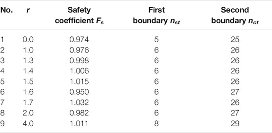
TABLE 1. Calculation table of failure plane search of the south Anhui slope under the action of a horizontal quasi-static force.
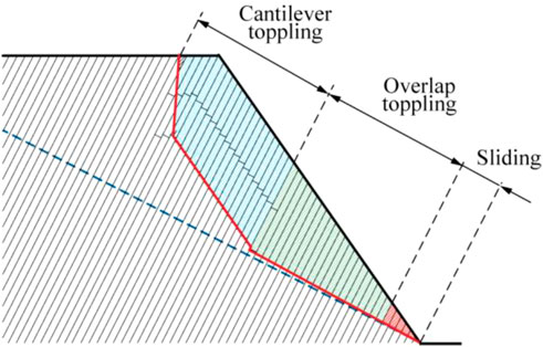
FIGURE 9. Failure surface and instability zoning of the anti-dip rock slope in southern Anhui (cantilever toppling zone; overlap toppling zone; sliding zone).
To further explore the influences of seismic load on the failure of anti-dip rock slopes, the slope failure modes under different seismic loads, i.e., 0.4, 0.6, 0.8, and 1.0 g were analyzed, and the results are shown in Table 2. According to the results, the slope failure surface and failure zone are identified in Figure 10. The red, green, and blue areas are the sliding, overlap toppling, and cantilever toppling zones, respectively.
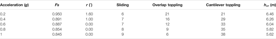
TABLE 2. Stability and zoning of the anti-dip rock slope in southern Anhui under different seismic loads.
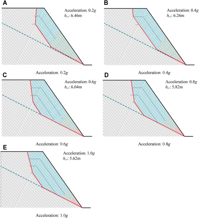
FIGURE 10. Stability analysis of the anti-dip rock slope in southern Anhui under different seismic loads. (A) Stability analysis at 0.2 g acceleration; (B) Stability analysis at 0.4 g acceleration; (C) Stability analysis at 0.6 g acceleration; (D) Stability analysis at 0.8 g acceleration; (E) Stability analysis at 1.0 g acceleration.
With the increasing seismic load, the failure surface of the sliding-toppling zone decreased significantly, and as the critical fracture depth of the cantilever toppling zone decreased, the failure surface of the cantilever toppling zone increased significantly. Moreover, as the sliding zone increased, the overlap toppling zone decreased, and the cantilever toppling zone consequently increased. The multi-level fracture occurred when the seismic acceleration was large. Therefore, the stability of rock slopes decreased under seismic loads. As the number of rock strata layers with overlap toppling failure decreased, the number of rock layers with cantilever toppling and rock layers with sliding failure increased. The axial stress of the rock block was increased and became closer to reaching the tensile strength of the rock block due to the influence of seismic force. Hence, combined with the enhanced sliding potential of the sloping block, the cantilever toppling rock increased significantly.
Conclusion
In this paper, the pseudo-static method was used to establish the mechanical model of an anti-dip rock slope, analyze the failure mode and mechanism, explore the failure surface and evaluate the stability of the slope under different seismic loads, and obtain the following main conclusions:
1) The slope stability decreased under seismic load, and with the increasing seismic load, the sliding area increased, whereas the overlap toppling zone decreased.
2) The decrease in the critical fracture depth of the cantilever toppling zone firstly increased the area of the cantilever toppling zone, but the area finally decreased under a significant strong earthquake scenario.
3) An increase in the number of rock layers with sliding failure increased the number of rock layers with cantilever toppling failure; in contrast, the number of rock layers with overlapping toppling failure decreased.
Data Availability Statement
The raw data supporting the conclusions of this article will be made available by the authors, without undue reservation.
Author Contributions
HZ: Methodology, software, validation, investigation, data curation, visualization, writing-review and editing; YW: Software, validation, investigation, visualization, writing-review and editing; SH: Investigation, visualization, writing; LZ: Conceptualization, investigation, visualization, writing, project administration, funding acquisition; YM: Methodology, writing-review and editing, supervision.
Funding
This study was funded by the National Key R&D Program of China (No. 2017YFC1501001-03), the National Natural Science Foundation of China (No. 41977233), and the Scientific Research Foundation of Fuzhou University (No. XRC-18053).
Conflict of Interest
The authors declare that the research was conducted in the absence of any commercial or financial relationships that could be construed as a potential conflict of interest.
Publisher’s Note
All claims expressed in this article are solely those of the authors and do not necessarily represent those of their affiliated organizations, or those of the publisher, the editors and the reviewers. Any product that may be evaluated in this article, or claim that may be made by its manufacturer, is not guaranteed or endorsed by the publisher.
Acknowledgments
Thanks are due to Mr. Zhiyuan Zhu for assistance with editing the manuscript and preparing the figures to this paper.
References
Aydan, O., and Amini, M. (2009). An Experimental Study on Rock Slopes against Fexural Toppling Failure under Dynamic Loading and Some Theoretical Considerations for its Stability Assessment[J]. J. Sch. Mar. Sci. Technol. 7 (2), 25–40.
Bobet, A. (1999). Analytical Solutions for Toppling Failure. Int. J. Rock Mech. Mining Sci. 36 (7), 971–980. doi:10.1016/s0148-9062(99)00059-5
Chen, C.-C., Li, H.-H., Chiu, Y.-C., and Tsai, Y.-K. (2020). Dynamic Response of a Physical Anti-dip Rock Slope Model Revealed by Shaking Table Tests. Eng. Geology. 277, 105772. doi:10.1016/j.enggeo.2020.105772
Chen, C. X., Zheng, Y., and Sun, C. Y. (2016). An Analytical Approach on Flexural Toppling Failure of Counter-tilt Slopes of Layered Rock[J]. Chin. J. Rock Mech. Eng. 35 (11), 2174–2187. doi:10.13722/j.cnki.jrme.2016.1001
Chen, Y. M., and Teng, G. L. (2011). A Preliminary Discussion on the Characteristics of Landslide-Collapse Disaster Induced by Wenchuan Earthquake in Gansu and Countermeasures for Disaster Mitigation [J]. Northwest. Seismological J. 33 (B08), 451–455. doi:10.3969/j.issn.1000-0844.2011.z1.097
Fan, G., Zhang, J., Wu, J., and Yan, K. (2016). Dynamic Response and Dynamic Failure Mode of a Weak Intercalated Rock Slope Using a Shaking Table. Rock Mech. Rock Eng. 49, 3243–3256. doi:10.1007/s00603-016-0971-7
Feng, X., Jiang, Q., Zhang, X., and Zhang, H. (2019). Shaking Table Model Test on the Dynamic Response of Anti-dip Rock Slope. Geotech Geol. Eng. 37, 1211–1221. doi:10.1007/s10706-018-0679-4
Goodman, R. E., and Bray, J. W. (1976). “Toppling of Rock Slopes[C],” in Proceedings of the Specialty Conference on Rock Engineering for Foundations and Slopes (Boulder: American Society of Civil Engineering), 2, 739–760.
Guo, S., Qi, S., Yang, G., Zhang, S., and Saroglou, C. (2017). An Analytical Solution for Block Toppling Failure of Rock Slopes during an Earthquake. Appl. Sci. 7 (10), 1008. doi:10.3390/app7101008
Huang, F., Huang, J., Jiang, S., and Zhou, C. (2017). Landslide Displacement Prediction Based on Multivariate Chaotic Model and Extreme Learning Machine. Eng. Geology. 218, 173–186. doi:10.1016/j.enggeo.2017.01.016
Huang, F., Tao, S., Chang, Z., Huang, J., Fan, X., Jiang, S.-H., et al. (2021). Efficient and Automatic Extraction of Slope Units Based on Multi-Scale Segmentation Method for Landslide Assessments. Landslides 18, 3715–3731. doi:10.1007/s10346-021-01756-9
Huang, F., Yan, J., Fan, X., Yao, C., Huang, J., Chen, W., et al. (2021). Uncertainty Pattern in Landslide Susceptibility Prediction Modelling: Effects of Different Landslide Boundaries and Spatial Shape Expressions. Geosci. Front. 2021, 101317. doi:10.1016/j.gsf.2021.101317
Huang, R. Q. (2007). Large-scale Landslides and Their Sliding Mechanisms in China since the 20th Century[J]. Chin. J. Rock Mech. Eng. 26 (3), 433–454. doi:10.3321/j.issn:1000-6915.2007.03.001
Huang, R. Q., and Li, W. L. (2009). Analysis on the Number and Density of Landslides Triggered by the 2008 Wenchuan Earthquake, China[J]. J. Geol. Hazards Environ. Preservation 20 (3), 1–7.
Huang, R., Zhao, J., Ju, N., Li, G., Lee, M. L., and Li, Y. (2013). Analysis of an Anti-dip Landslide Triggered by the 2008 Wenchuan Earthquake in China. Nat. Hazards 68 (2), 1021–1039. doi:10.1007/s11069-013-0671-5
Huang, R., Zhao, J., Ju, N., Li, G., Lee, M. L., and Li, Y. (2013). Analysis of an Anti-dip Landslide Triggered by the 2008 Wenchuan Earthquake in China. Nat. Hazards 68, 1021–1039. doi:10.1007/s11069-013-0671-5
Hungr, O., Leroueil, S., and Picarelli, L. (2014). The Varnes Classification of Landslide Types, an Update. Landslides 11 (2), 167–194. doi:10.1007/s10346-013-0436-y
Ka, M. C., Chen, R. S., Wu, W. J., and Liu, G. (2011). Analysis on Features of Earthquake-Induced Landslide in Heavy Layer and Anti-dip Stratified Rock Slope[J]. Northwest. Seismological J. 33 (S), 408–412. doi:10.3969/j.issn.1000-0844.2011.z1.088
Keefer, D. K. (2002). Investigating Landslides Caused by Earthquakes - A Historical Review[J]. Surv. Geophys. 23 (6), 473–510. doi:10.1023/a:1021274710840
Keefer, D. K. (1984). Landslides Caused by Earthquakes. Geol. Soc. America Bull. 95, 406–421. doi:10.1130/0016-7606(1984)95<406:lcbe>2.0.co;2
Li, G., Huang, R. Q., Ju, N. P., Zhao, J. J., and Jia, J. (2011). Cause Mechanism of Giant Anti-incline Ganhekou Landslide Induced by Wenchuan Earthquake [J]. Water Resour. Power 29 (4), 118–121. doi:10.3969/j.issn.1000-7709.2011.04.039
Li, L.-q., Ju, N.-p., Zhang, S., and Deng, X.-x. (2017). Shaking Table Test to Assess Seismic Response Differences between Steep Bedding and Toppling Rock Slopes. Bull. Eng. Geol. Environ. 78, 519–531. doi:10.1007/s10064-017-1186-1
Liu, C. H., and Chen, C. X. (2010). Analysis of Toppling Failure of Rock Slopes Due to Earthquake[J]. Chin. J. Rock Mech. Eng. 29 (z1), 3193–3198. CNKI:SUN:YSLX.0.2010-S1-088.
Liu, H., Zhao, Y., Dong, J., and Wang, Z. (2021). Experimental Study of the Dynamic Response and Failure Mode of Anti-dip Rock Slopes. Bull. Eng. Geol. Environ. 80, 6583–6596. doi:10.1007/s10064-021-02313-3
Lu, H. F., Liu, Q. S., and Chen, C. X. (2012). Improvement of Cantilever Beam Limit Equilibrium Model of Counter-tilt Rock Slopes[J]. Rock Soil Mech. 33 (2), 577–584. doi:10.3969/j.issn.1000-7598.2012.02.040
Miki, S., Sasaki, T., Koyama, T., Nishiyama, S., and Ohnishi, Y. (2010). Development of Coupled Discontinuous Deformation Analysis and Numerical Manifold Method (NMM-DDA)[J]. Int. J. Comput. Methods 7 (1), 131–150. doi:10.1142/s021987621000209x
Ning, Y., Zhang, G., Tang, H., Shen, W., and Shen, P. (2019). Process Analysis of Toppling Failure on Anti-dip Rock Slopes under Seismic Load in Southwest China. Rock Mech. Rock Eng. 52, 4439–4455. doi:10.1007/s00603-019-01855-z
Nonomura, A., and Hasegawa, S. (2013). Regional Extraction of Flexural-Toppled Slopes in Epicentral Regions of Subduction Earthquakes along the Nankai Trough Using DEMs. Environ. Earth Sci. 68, 139–149. doi:10.1007/s12665-012-1722-z
Xu, Q., Pei, X. J., and Huang, R. Q. (2009). Large-scale Landslides Induced by Wenchuan earthquake[M]. Beijing: Science Press. doi:10.3799/dqkx.2011.119
Yagoda-Biran, G., and Hatzor, Y. H. (2013). A New Failure Mode Chart for Toppling and Sliding with Consideration of Earthquake Inertia Force. Int. J. Rock Mech. Mining Sci. 64, 122–131. doi:10.1016/j.ijrmms.2013.08.035
Yang, G. X., Ye, H. L., Wu, F. Q., Qi, S. W., and Dong, J. Y. (2012). Shaking Table Model Test on Dynamic Response Characteristics and Failure Mechanism of Anti-dip Layered Rock Slope[J]. Chin. J. Rock Mech. Eng. 31, 2214–2221. doi:10.3969/j.issn.1000-6915.2012.11.009
Zhang, H. N., Chen, C. X., Zheng, Y., Zhou, Y. C., and Deng, Y. Y. (2018). Analytical Study on Block-Flexure Toppling Failure of Rock Slopes Subjected to Seismic Loads[J]. China J. Highw. Transportation 31 (2), 75–85. doi:10.19721/j.cnki.1001-7372.2018.02.008
Zhang, Z., Wang, T., Wu, S., and Tang, H. (2015). Rock Toppling Failure Mode Influenced by Local Response to Earthquakes. Bull. Eng. Geol. Environ. 75, 1361–1375. doi:10.1007/s10064-015-0806-x
Zhao, J. J., Ju, N. P., Li, G., and Huang, R. Q. (2010). Failure Mechanism Analysis of Guantan Landslide Induced by Wenchuan Earthquake[J]. J. Geol. Hazards Environ. Preservation 21 (2), 92–96. doi:10.3969/j.issn.1006-4362.2010.02.021
Zheng, Y., Chen, C. X., Zhu, X. X., Ou, Z., Liu, X. M., and Liu, T. T. (2014). Analysis of Toppling Failure of Rock Slopes Subjected to Seismic Loads[J]. Rock Soil Mech. 35 (4), 1025–1032. doi:10.16285/j.rsm.2014.04.010
Keywords: anti-dip rock slope, flexural toppling, limit equilibrium, seismic load, stability analysis
Citation: Zhang H, Wu Y, Huang S, Zheng L and Miao Y (2022) Analysis of Flexural Toppling Failure of Anti-Dip Rock Slopes Due to Earthquakes. Front. Earth Sci. 9:831023. doi: 10.3389/feart.2021.831023
Received: 07 December 2021; Accepted: 15 December 2021;
Published: 31 January 2022.
Edited by:
Xiaodong Fu, State Key Laboratory of Geomechanics and Geotechnical Engineering, Institute of Rock and Soil Mechanics (CAS), ChinaReviewed by:
Zhenghu Zhang, Dalian University of Technology, ChinaTiexin Liu, Dalian Maritime University, China
Copyright © 2022 Zhang, Wu, Huang, Zheng and Miao. This is an open-access article distributed under the terms of the Creative Commons Attribution License (CC BY). The use, distribution or reproduction in other forums is permitted, provided the original author(s) and the copyright owner(s) are credited and that the original publication in this journal is cited, in accordance with accepted academic practice. No use, distribution or reproduction is permitted which does not comply with these terms.
*Correspondence: Yuanbing Miao, MTAyNDE2NTJAcXEuY29t