 Xing Huang
 Linfeng Li2
 Chaofan Zhang
95% of researchers rate our articles as excellent or good
Learn more about the work of our research integrity team to safeguard the quality of each article we publish.
Find out more
ORIGINAL RESEARCH article
Front. Earth Sci. , 02 December 2021
Sec. Geohazards and Georisks
Volume 9 - 2021 | https://doi.org/10.3389/feart.2021.795457
This article is part of the Research Topic Advances in Modeling, Assessment, and Prevention of Geotechnical and Geological Disasters View all 44 articles
Shield tunneling in highly fractured karst water-rich conditions easily results in water inrush disaster or even causes the roof of the karst caves to collapse. Severe water inrush disasters have occurred during the EPB (earth pressure balance) shield machine of the Jinan Metro Line R1 advanced through a karst and fissure groundwater-rich limestone ground in the spring area. To cope with the extreme water inrush risk, a multi-step combined control technology was put forward. First, a detailed geological exploration was carried out by ahead geophysical prospecting using high-density resistivity method, geological radar, etc., and geological borehole drilling was conducted from the ground surface before excavation. As a result, the distribution orientation, size, fissure development degree, and water inflow channel within the surrounding rock of the karst caves were detected. Second, multi-step grouting was performed to reinforce the surrounding rock, including pre-grouting treatment and filling rock blocks to the big karst caves from the ground surface, multiple grouting with a small amount of inert slurry each time inside the tunnel, and secondary circumferential hoop grouting at the shield tail. Third, the tunneling process was optimized, including optimizing the tunneling parameters, making full use of the air-pressurized tunneling technology of the EPB to press bentonite into the fractures around the excavation cabin to seal the fissure water, and using the drainage system of EPB and muck improvement technology to reduce the water inrush disaster. Meanwhile, shield protection slurry technology is applied to cutter inspection and replacement in the pressurized chamber under dynamic water flow environment of the spring terrain. The practice shows that the water inrush on the tunnel face is obviously alleviated after the shield machine advanced into the grouting area. According to statistics, the water inflow on the tunnel face decreases from about 4 m3/h before treatment to less than 0.3 m3/h after the abovementioned control, and the water seepage between the segmental linings reduces to almost zero. The average advance rate increased from 3 m/day without stopping or even zero when the shield machine needs to shut down 2–3 days for drainage to about 6 m/day. In addition, the treatments prevented the shield machine from jamming and the head descending disaster. This study provided a reliable control method for shield tunneling through the karst and fissure water-rich area and played an essential role in protecting the spring water.
With the continuous increase of metro lines, more and more metro tunnels will inevitably be built in complex hydrogeological environments. Among them, karst terrains are widely distributed in China, which is the most common geological problem during metro construction (Li et al., 2020a; Kang et al., 2021; Zheng et al., 2021). Because of their strong concealment, high complexity, and difficulty in treatment, they are prone to cause the shield machine heading down and subsidence, water and mud inrush disaster, and tunnel face instability. For example, a large ground collapse, water inrush, and mud outburst (10,540.8 m3) occurred in the water-rich area of Qingdao line 4 (China., 2021; Yan et al., 2021).
Jinan is a spring city. The Jinan karst spring area is located in the central and western parts of Shandong Province (Qi et al., 2016). The average daily flow of the spring group is as high as 36.6 × 10⁴ m3/day (Guan et al., 2019). Because of the impact of the dynamic water environment in the spring area, various geological disasters such as ground subsidence, karst cave collapse, and surrounding rock instability are often encountered during the metro tunnels construction, as well as various water environmental problems such as water inrush disaster, groundwater table decline, and water pollution. Among them, Jinan Metro Line R1 is located in a giant natural underground reservoir in the water source of western Jinan, with groundwater reserves of more than 10 billion m3 and complex hydrogeological conditions. The metro line is tunneling through a vast limestone-bearing mixed ground. In addition, many karst caves are distributed in this limestone section. Groundwater mainly comes from the limestone karst and fissures, which is prone to induce water inrush disasters. The construction of urban rail transport projects in water-rich karst areas has enormous risks, such as the roof of the karst cave may collapse. The mud outbursts and water inrushing in the karst cave have become the most severe geological disaster at present, which may lead to flooding of tunneling equipment or even fatal crash.
Previous scholars have performed a lot of laboratory model tests and theoretical and numerical simulation calculations to reveal the mechanism of water inrush hazard in karst and water-rich grounds and provide guidance for water inrush prevention. In terms of model tests, Li et al. (2020b) developed a model test system for studying the water inrushes evolution to reveal the water inrush mechanism triggered by confined karst caves during shield excavation. Using this test system, a model test of the water inrush under EPB (earth pressure balance) shield machine tunneling in the Jinan metro was performed, in which the displacement, stress, and seepage pressure variations were analyzed. Li et al. (2020c) conducted a large-scale three-dimensional geo-mechanical model test on a compound EPB shield tunnel in the “spring city” Jinan metro to study the surrounding rock stability when approaching a cave with confined water. The rock failure and water inrush were mainly resulted from the combining effect of the shield excavation disturbance and the confined water in the cave. The water inrush could be estimated and predicted in terms of the displacement and the seepage during the water inrush in the shield tunnel, the moisture content of the muck, and the ground settlement. In addition, theoretical calculation and numerical simulation methods were proposed. For example, Huang et al. (2017) derived an analytical solution of the collapse surface from a variational calculation on the basis of the upper bound theorem to predict the rock mass collapse when excavated above a karst cave. Accordingly, a formula for computing the minimum thickness to prevent rock pillars collapse is derived. Zhang K. et al. (2018) presented a karst feature predicting method by performing an initial karst evaluation using a fuzzy assessment system to first evaluate the underground karst state and then use geological investigations to update the karst state. Wu et al. (2019) developed computational models to estimate the required minimum rock stratum thickness between the tunnel face and the cave for two types of filled karst caves, with water and with water-mud mixture, respectively. Lee and Moon. (2020) analyzed the change of groundwater regime during excavation in limestone strata containing cavity network by three-dimensional numerical simulation and revealed the groundwater level drawdown mechanism followed by ground subsidence. Then, they proposed an analytical solution for determining the cutoff grouting range to minimize the groundwater inflow during tunneling in a fractured zone. Guo et al. (2020) established a streamline theoretical model for grouting diffusion trajectory with flowing water and analyzed the influence of boundary effect on the grouting diffusion law. Xiong et al. (2020) investigated the deformation and failure process and instability mechanism of karst mountain with deep and large fissures under the coupling of underground mining and fissure water seepage using a UDEC code and analyzed that the mining-induced failure in the mountain with deep and large fissures is additionally the effect of fissure water seepage on the deformation of mining mountain. The model test and the theoretical and numerical calculations have played an important role in understanding the mechanism of water inrush hazards and can provide certain guidance for water inrush prevention. However, these methods can not completely reproduce the water inrush process due to a lot of assumptions and simplification. The guidance to the field water inrush treatment is limited.
Besides, to prevent and treat the karst and water inrush disaster, ahead prospecting and monitoring, and field prevention and control technologies have been widely studied. Regarding advanced geological prospecting and field monitoring, Hu et al. (2009) indicated that the high-density resistivity method is economical, fast, applicable, and effective geophysical exploration, and the survey results are easy to interpret. However, because of the limited detection accuracy of the high-density resistivity method, it must be verified by drilling to improve its accuracy. Carrière et al. (2013) proposed a combining electrical resistivity tomography and ground penetrating radar method to investigate the geological structure of unsaturated karst zones. Li et al. (2015) reviewed the direct current (DC) resistivity detecting and monitoring method for water inrush. They indicated that the DC resistivity method is an important and useful geophysical detection method for water inrush hazard prediction. Liu et al. (2019) conducted seismic ahead prospecting to detect the fractured and karst zones and then applied resistivity ahead prospecting to investigate the water-bearing condition of the fractured and karst zones in limestone strata of Jilin Yinsong TBM project (China). Wang et al. (2021) presented a real-time water inrush monitoring system using the accurate measurement of sensors and wireless transmission bands and developed an early warning method for multi-information interval fusion on the basis of evidence and fuzzy set theory to achieve the fusion of the time series monitoring data. Li. (2021) applied ground-penetrating radar in the karst-rich section of the tunnel. Advanced drilling and exploration proved that the ground-penetrating radar has high precision, efficiency, and anti-interference capacity. In addition, many field treatment methods were presented. For example, Xue et al. (2021) presented genesis, evolution, and prevention measures of water and mud inrush hazards, indicating that different ahead geological prospecting techniques were applied to identify the water-mud-bearing structure initially; then, the risk was evaluated to determine the probability of inrush hazards and provide guidelines for hazard management; meanwhile, the evolution of water inrush channels can be monitored via microseismic monitoring and can be blocked by grouting technology; finally, plugging water exhibiting a considerable flow rate can be treated by dynamic water grouting. Liu et al. (2021) analyzed the grout penetration process and grouting parameters in fractured rock mass. Zhang C. et al. (2018) developed a new grouting material, which takes bentonite and cement as the base material and then adds a curing agent to form excellent fluidity, stability, and scour resistance, to fill karst caverns when there is flowing underground water ahead of the shield tunnel construction. Liu. (2018) studied the gushing prevention technology for shield tunneling in metro line water-rich strata, including shield machine modification, soil improvement, polymer injection, and control of tunneling parameters. Zhang. (2018c) analyzed the prevention and treatment of geohazards during tunneling in groundwater-rich mylonitic faults in Guangzhou. Metro Line No. 7 through tail grouting material optimization, advanced ground monitoring, grouting treatment, shield machine modification, and feedback data monitoring. Niu et al. (2020) introduced a full-section curtain grouting treatment method in fully weathered granite strata for the Guangxi Junchang tunnel. Different kinds of grouting materials were used in different hydrological conditions. In addition, transient electromagnetic methods, water inflow analysis, borehole investigation, and P-Q-T method were applied to evaluate the grouting effect. Yang et al. (2020) proposed a controllable grouting method and two corresponding grouting materials to pre-reinforce the underwater karst region before the shield machine passing in the tunnel of Changsha Metro Line 3. The karst caves were pre-grouted by a so-called vertical layered controllable grouting, which ensured the grouted rocks not only can be easy cut by the shield machine but also possess sufficient strength to keep the tunnel stability. Yan et al. (2021) put forward a set of remedial treatments for ground caves, including filling the caves, reinforcing the advance core ahead of the tunnel face, and conducting the porepoles to form a protective shell. These instruments were applied in the Qingdao Line 4, China. These ahead geological prospecting, prevention, and control technologies provide useful measures for water inrush hazard. However, most of the present ahead prospecting and control methods are used in the traditional mountain tunnels or TBM tunnels. In addition, the control measures such as grouting are usually performed by experience, rather than according to the advance detection results. The burial depth, ground conditions, and treatment environment are quite different from the mountain tunnels and TBM tunnels. Furthermore, under the special excavation characteristics of shield tunneling, synthetical control measures from the aspects of ahead geological exploration, pretreatment, undergrounding grouting, and tunneling optimization are lacking.
To cope with the water inrush hazard in the highly fractured karst stratum under the dynamic spring water conditions in spring areas, based on Jinan Metro Line R1, first, this paper first proposes a comprehensive detection method combining ahead geophysical prospecting and borehole drilling from the ground surface to investigate the karst and fissures distribution and groundwater flow path. Second, according to the detection results, a multi-step grouting technology for water-stopping is put forward, including pre-grouting treatment from the ground surface, underground grouting using inert slurry, and secondary circumferential hoop grouting at the shield tail. Meanwhile, an optimized shield tunneling technology is presented. Accordingly, a multi-step combined control technology for karst and fissure water inrush disaster during shield tunneling is developed, which significantly benefits spring water protection and tunneling safety.
R1 Line is the first metro line in spring city Jinan. The R1 Line is located in the west of Jinan, with a total length of 26.1 km and 11 stations, consisting of an overpass section of 16.2 km, a transitional section of 0.2 km, and an underground tunneling section of 9.7 km. This paper studies the tunneling section from Wangfuzhuang Station to Dayangzhuang Station of the Jinan Metro Line R1. The line is tunneling eastward along Liuchangshan Road starting from Wangfuzhuang Station, turns north to Dangyang Road, and then goes northward along Dangyang Road to, finally, Dayangzhuang Station (Figure 1). This tunneling section has a total length of 3,754 m and uses four shield machines.
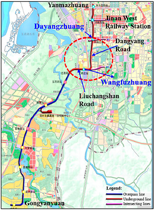
FIGURE 1. Schematic diagram of Jinan Metro Line R1.
The R1 Line is located in a giant natural underground reservoir in the water source of western Jinan, a spring city. The groundwater reserves are more than 10 billion m3. The geological conditions are complex. The metro line passes through complex formations such as water-rich silt, pebble, high-strength hard rock, and karst caves. It is the first time to achieve the harmonious symbiosis of springs and metros to realize the safe and efficient metro lines construction in the complex environment of springs. However, there is no mature experience to follow. After 30 years of analysis, argumentation, and construction planning, Jinan has proposed the planning and construction principles of “spring protection priority” and the guiding ideology of “avoiding the spring and elevation the lines when needed” for the first time. After nine rounds of experts’ argumentation, it was believed that the routes, laying methods, and burial depths of the planned R1 Line have almost no impact on the spring water gushing. If reasonable treatment measures are taken, then the impact is controllable. Therefore, it is necessary to adopt detailed detection and control technology for the metro tunnels construction under the dynamic groundwater environment with rich karst caves and fissure water in the Jinan spring area.
Jinan Metro Line R1 passes through limestone strata in two tunneling sections. The first limestone section ranges at the Chainage K30 + 505 m–K30 + 768 m (left tunnel) and K30 + 493 m–K30 + 791 m (right tunnel), respectively. The second limestone section ranges at the Chainage K30 + 915 m–K31 + 387 m (left tunnel) and K30 + 875 m–K31 + 384 m (right tunnel), respectively. The geological profile is shown in Figure 2.
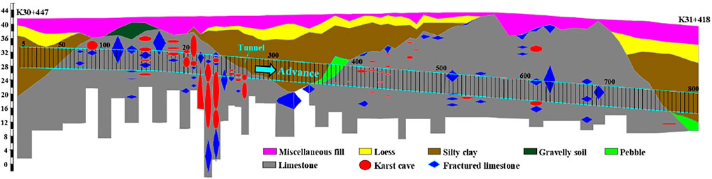
FIGURE 2. Geological profile of the limestone tunneling section.
In the Jinan Metro Line R1, because of the rich tectonic fractures in the soluble limestone strata and because of the abundant flowing groundwater with dissolution capacity, caves are formed with different sizes, shapes, and burial depths under the groundwater dissolution and erosion. The geological survey discovered a large number of karst caves, and the karst and fissure water is rich. The number of karst caves with large size from Wangfuzhuang Station to Dayangzhuang Station is as high as about 150. At the same time, bead-shaped karst caves are revealed. Borehole drilling disclosed that limestone dissolution is severe, and local honeycomb and pinhole-like solution pores and cracks are abundantly distributed. The caves are mainly filled with cohesive soil and fractured rocks of different sizes and content. Under the action of long-term groundwater, the scale of karst caves may be further expanded, and the stability of karst caves is poor. In addition, the uniaxial compressive strength of medium-weathered limestone is 33.5–83.2 MPa with the standard value of 64 MPa and a maximum of 112 MPa. The RQD (rock quality designation) is between 5 and 50, generally 5 and 25. Accordingly, the surrounding rock quality is classified as extremely poor.
The groundwater mainly exists in limestone karst and fissures. The groundwater table is 27.06–32.05 m, and the groundwater burial depth is 11.2–14.6 m. The hydrogeological map (Figure 3) shows that the tunnels pass through the medium-weathered limestone strata, with the most abundant groundwater content in central and western Jinan. The water output of a single well is almost greater than 10,000 m3/day, and the groundwater is pressure-bearing. The most apparent characteristic of the spring areas is that the groundwater flows dynamically, which makes the water inrush disaster more serious and aggravates the difficulty of prevention and control of the water inrush disaster. The water supply is tremendous, which severely threatens the shield machine.

FIGURE 3. Hydrogeological map of the limestone section on the right line.
The surface water body that the tunnels cross is mainly the Lashan River (Figure 1). The total length of the Lashan River is about 14.6 km. In addition, about 8 km of the Lashan River flows in the middle of the city. The river is about 50 m wide and 3–6 m deep. The R1 Line crosses the Lashan River near the Chainage K31 + 600 m. In addition, the tunnels pass through another river near the Chainage K30 + 300 m, with a width of about 15 m and a depth of about 2–4 m. Once the cracks, karst caves, and the river above intersect after excavation, the water in the river will be continuously poured into the tunnel, resulting in severe water inrush disasters.
Special attention should be paid to tunnels advancing through overlying rivers and reservoirs, especially in karst and fissure-rich areas. For example, on July 15, 2021, the Shijingshan tunnel of the Zhuhai Xingye Express Line locates at a position of 1.16 km, and the tunneling section was beneath the reservoir. Unfortunately, the surrounding rock was connected to the above reservoir after excavation, resulting in a severe water inrush accident, resulting in the deaths of 14 workers (China.com, 2021).
To effectively deal with the limestone-bearing mixed ground, the shield machines of the R1 Line dual tunnels adopt the EPB-type mixshield machine (Figure 4) developed by China Railway Engineering Equipment Group. The cutterhead adopts a composite design of four spokes and four panels. It is equipped with a composite cutterhead with an excavation diameter of 6,680 mm and an opening ratio of 40%. A total of 41 disc cutters and 40 scrapers are installed on the cutterhead. The disc cutters are interchangeable and can rotate in both directions. The length of the head of the shield machine is 8,389 mm, and the length of the whole machine is 85 m. The used two shield machines were designed according to the typical mixed ground, rather than considering the water inrush disaster prevention specially.
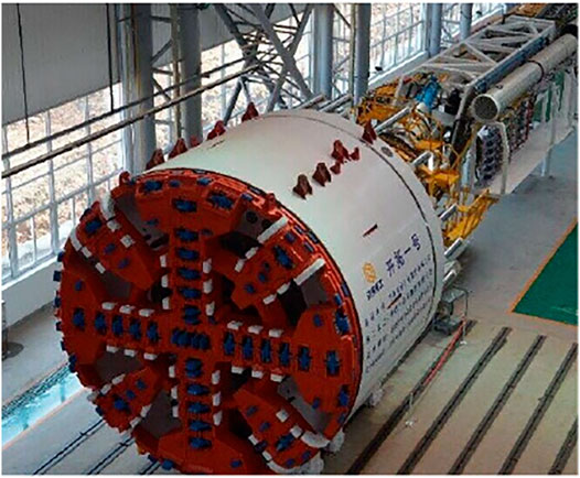
FIGURE 4. The used EPB shield machine.
The parameters of the screw conveyor used for slag and chips discharge are as follows (Table 1).
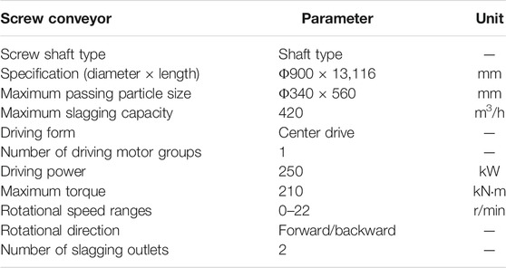
TABLE 1. Screw conveyor parameters.
During shield tunneling in the medium-weathered limestone ground, the karst water supply is large, water inflows seriously at the segmental linings and the tunnel face, and the screw conveyor inrush is severe (Figure 5).
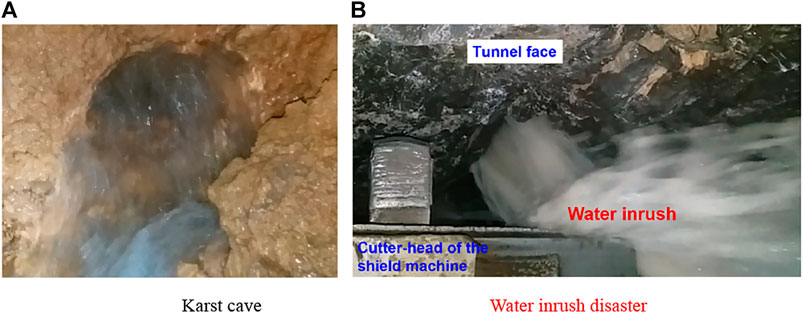
FIGURE 5. Water inrush at the tunnel face. (A) Karst cave. (B) Water inrush disaster.
Many water inrush disasters have occurred during shield tunneling. Typical karst and fissure water inrush disasters include the following.
The shield machine of the left line from the air shaft to Dayangzhuang Station entered into the second section of the medium-weathered limestone stratum on June 16, 2017, since it started tunneling on March 13, 2017. There was an interlayer of silty clay and pebbles on the tunnel roof, and the tunnel is 15‰ downhill. The water increased significantly when the shield machine advanced to the 395th ring in the soil-rock mixed ground (the upper soft soil and bottom hard rock). In the subsequent 10 rings, the water flow increased and entered into the full-face limestone. Fractured limestone masses and fissure water were abundant in the ground. On the morning of June 19, when the shield machine advanced to the 407th ring, the screw conveyor began to gush, and the water flow was tremendous (Figure 6A). There was almost no mud in the slag, all of which were rock chips formed by the medium-weathered limestone blocks and rock powder generated by the cutterhead grinding the limestone (Figure 6B).
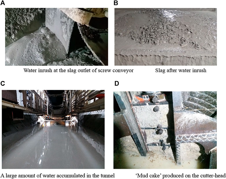
FIGURE 6. Risks to shield tunneling caused by severe water inrush. (A) Water inrush at the slag outlet of screw conveyor. (B) Slag after water inrush. (C) A large amount of water accumulated in the tunnel. (D) “Mud cake” produced on the cutterhead.
On July 23, 2017, when the shield machine on the right line advanced to the 388th ring, it began to gush due to the influence of the groundwater table. The position was roughly the same as the position where the inrush started on the left line, which was close to the starting position of the second limestone section. By analyzing the on-site tunneling situation of the shield machine on the left and right tunnels, the location where water inrush began, the fissure water replenishment capacity in limestone was strong. When the tunneling stops for more than 10 min, the groundwater table in front of the shield machine can be replenished to about 3 m above the roof (the water pressure reaches about 0.3 bar). Subsequently, when the shield machine on the left line was tunneling to the 580th ring, the groundwater level on the roof reached about 5 m (the water pressure was about 0.5 bar). Filed observations showed the water supply in the earth cabin has reached 400–600 m3/h. At the same time, with the burial depth of the tunnel continuing to increase, the water inflow continues to grow, and severe water inrush disasters occurred.
The challenges and risks to shield tunneling caused by severe water inrush are summarized as follows (Figure 6).
In the shield excavation section, the karst water replenishment capacity can reach 400–600 m³/h, or even water inrush disaster occurs, which affects the workability of muck improvement. Big rock blocks in the excavation cabin cannot be discharged fluently, resulting in massive slag accumulation in the cabin. The groundwater pressure is immense. When the shield tail reaches the karst or the highly fractured area, a large amount of karst water will scour the synchronous grout, causing the grouting slurry to be washed away to the low-pressure area such as the soil cabin, and the grouting slurry at the shield tail is prone to be leaked, which finally affects the construction quality and even results in the segmental lining floating up. The water is accumulated in front, back, and other directions of the shield, which seriously affects the slag discharge capacity of the screw conveyor.
The water inrush disaster caused the belt conveyor to leak muck and slag, which gathered to the shield tail. More slags accumulated in the segmental linings assembly area at the shield tail, resulting in the segment linings that could not be installed normally. Before segment assembling, it takes a long time to manually clean slags at the shield tail, which affects the assembling efficiency and quality. The assembling time per ring increases by about 4 h.
Compared with the first limestone tunneling section, because of the high strength of limestone, the advance rate is low, but the water content of the slag is small. Tunneling is not affected by the slag discharging, the tunneling can be smooth and continuous, and the daily advance rate can still reach 4–5 rings/day. However, after the water inrush hazards occur, the tunneling time per ring is longer, and the number of tunneling rings per day is less than three rings.
Because of the high strength of limestone, heavy groundwater inflow, and the low advance rate, the water inrush leads to poor slag discharge. The slag accumulated in the excavation cabin is ground into rock powder. In addition, the cutterhead operates for a long time, the temperature becomes higher, and the rock powder further formed “mud cake,” which reduces the opening rate of the cutterhead. A large amount of mud cake is cemented and accumulated at the slag discharge inlet of the screw, which affects the slag discharge, further affects the advance rate, shortens the service life of the cutters, and finally forms a vicious circle.
With the increasing water inflow, the slag output per ring increases, which is about 1.5 times that under normal conditions, increasing the horizontal and vertical transportation time and affecting excavation efficiency. The discharge of a large amount of mud and water reduces the horizontal transportation efficiency in the tunnel and restricts the discharge work of muck. The muck is transported outside after being separated from the water, which is time-consuming and labor-intensive.
Part of the limestone excavation section has strong karst development, with more than 100 karst caves and many fractured rocks and dissolved bodies. When the shield machine advanced to this section, the shield machine is easy to occur in posture deviation and head drop, which seriously affected the shield tunneling efficiency and safety. Moreover, during tunneling through the caves, the disturbance generated by shield tunneling may easily cause ground subsidence and pose a risk of ground collapse. In addition, during shield excavation, the groundwater flow rate increases, scouring the dissolved bodies and forming new cavities, and bringing hidden dangers to the safety and quality of shield tunneling and metro operations.
Under complex construction conditions, efficient and safe shield tunneling is seriously affected. The high-strength and water-rich karst formation aggravates the cutter wear. In addition, the frequency of opening the excavation cabin for cutter inspection and cutter replacement is relatively high. Although the tunnel face is relatively stable, because of a large amount of water, the strong and continuous drainage capacity for the underground water in the excavation cabin is needed in the opening cabin process for cutter inspection and replacement. Under such complex working conditions, there are huge operating risks and difficulties in the cutter inspection and replacement when opening the cabin under normal pressure and under earth pressure, resulting in a considerable risk of the whole shield machine being submerged.
Because of the shallow burial depth of the metro tunnel, ahead geophysical prospecting for karst and fissure water from the ground surface can be performed to provide a basis for subsequent water inrush disaster treatment. Therefore, it is proposed to use the high-density resistivity method, geological radar, and some other geophysical methods to detect the distribution of groundwater, karst caves, and fissures. Detailed detection was carried out using the inter-borehole resistivity CT scanning method and high-precision scanning imagery in critical and complex abnormal areas to detect the spatial distribution of major karsts and water inflow paths. The WGMD-9 super high-density electrical measurement system produced by Chongqing Benteng Digital Control Technical Institute (CQBTSK) was used in this detection (Figure 7A).
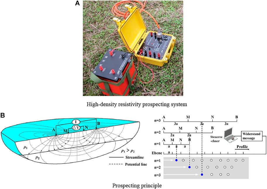
FIGURE 7. Schematic diagram of the high-density resistivity prospecting method. (A) High-density resistivity prospecting system. (B) Prospecting principle.
The karst caves in the limestone destroy the integrity and continuity of the rock mass. Therefore, the resistivity at this place will be higher than that of the intact rock. When the difference is noticeable, relatively high resistivity is produced (Figure 7B). Otherwise, the apparent resistivity contour fluctuates. In addition, after the karst cave is filled with water or mud, its resistivity is reflected by relatively low resistance. When the filled or unfilled caves appear, the resistivity value will fluctuate in the apparent resistivity contours. The field borehole drilling data show that the karst caves are mainly filled with mud and gravel, so the karst section is prospected using a low-resistance model. In the cross-section of the resistivity contour, the karst-rich area will be displayed as a low-resistance co-curved form or a low-resistance closed circle form.
The section from K30 + 400 m to K31 + 500 m of Jinan Metro Line R1 was advance geophysical prospected by high-density resistivity detecting method. The position and distribution of the karst and fractures 50 m beneath the ground surface were obtained. The detected caves with a larger volume are illustrated in Figure 8.
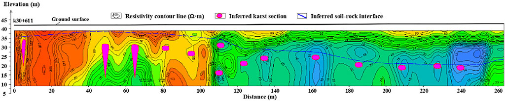
FIGURE 8. Ahead detection results of the karst caves.
Because of severe water inflow, the water supply paths need to be found. Borehole drilling was carried out to detect the karst cave position and water content for every 5 m along the tunnel central with an average depth of about 23 m (Figure 9). Of course, the borehole detecting depth increased with the increasing burial depth when the shield machine advanced to the second limestone tunneling section. The rock core strength and RQD were tested.
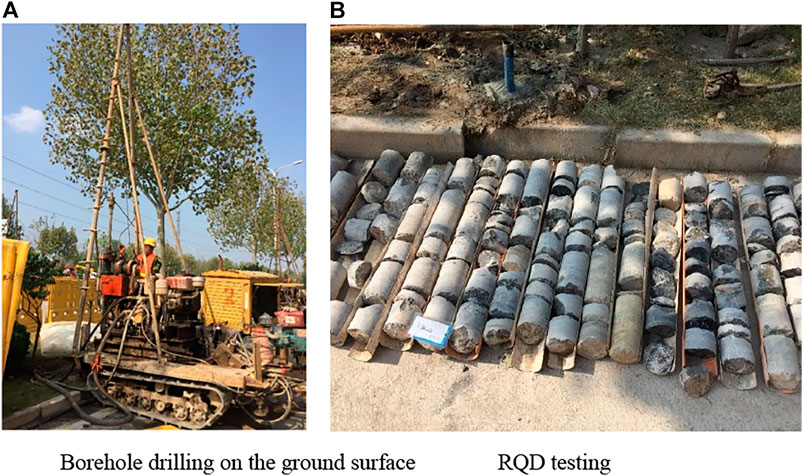
FIGURE 9. Borehole drilling for karst and fractures detection. (A) Borehole drilling on the ground surface. (B) RQD testing.
Borehole drilling is aimed at carrying out further exploration for the geophysical and initial geological survey where it showed that there are anomalies, to see whether there are karst caves and to determine the size and orientation of caves. If no caves are found, then the surrounding rock integrity can be measured too. As a result, the karst caves distribution and groundwater flow paths can be detected in detail to guide the next step of grouting reinforcement treatment.
Borehole exploration is carried out for the karst cave and soil cavern (Figure 10). In the first stage, taking the boreholes that reveal the karst and soil caves as the reference points, a row of detection boreholes that are also used as grouting holes will be drilled with an interval of 5.0 m along the tunneling direction to detect the cave boundary. In the second stage, a row of grouting boreholes is drilled perpendicular to the tunnel. In the third stage, the borehole from the center to the surrounding directions is explored to find the boundary of the cave.
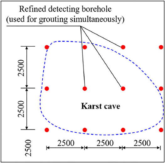
FIGURE 10. Layout of the refined boreholes.
After geophysical prospecting and borehole drilling detection, the karst caves and broken rocks’ distribution orientation, size, fissure development degree, and water inflow channel were detected in the limestone section (Figures 2, 8).
The total detected number of karst caves is 129, of which 79 karst caves sizes are smaller than 1 m, 50 are ≥1 m, 29 are ≥2 m, 23 are ≥3 m, and 12 are ≥5 m.
The exposed total number of holes is 12. There are three caves at 0–5 m above the tunnel roof; three are exposed in the tunnel zone; three are distributed at 0–5 m below the tunnel floor; and three are located at more than 5 m below the floor. Among them, the size of one exposed cave is ≥1 m, and size of the remaining exposed cavities is less than 1 m.
There are 29 karst caves distributed above the tunnel. Among them, 26 karst caves are exposed within 0–5 m above the tunnel roof; three karst caves are exposed beyond 5 m above the roof. Above the tunnel roof, there are 21 caves with the size that is less than 1 m, eight caves with ≥ 1 m, three caves with ≥2 m, and two caves with ≥3 m.
There are 65 karst caves exposed within the tunnel vicinity. It is revealed that there are 34 caves with the size that is less than 1 m, 31 caves with ≥1 m, 19 caves with ≥2 m, and 15 caves with ≥3 m.
There are 35 caves exposed below the tunnel. Among them, 25 karst caves are exposed within the range of 0–5 m below the tunnel floor and 10 karst caves are exposed at 5 m below the tunnel floor. There are 24 caves with less than 1 m exposed under the tunnel floor, 11 caves with ≥1 m, 7 caves with ≥2 m, and 6 caves with ≥3 m.
The revealed karst caves are classified as shallow cover types located below the current groundwater level and are affected by groundwater erosion and migration. The karst stability is generally medium, but the local stability is poor.
According to the above geological exploration results, positional relationships between the caves and the tunnel are determined. The ground pretreatment method should be conducted for the caves with beneficial ground surface treatment conditions. The pretreatment range of the karst caves is as follows (Figure 11):
1) All the caves in the upper part of the tunnel need to be treated, but the caves filled with hard plastic clay (N > 18) do not need to be treated, where N is a plasticity index.
2) The caves within the tunnel zone that filled with soft plastic clay (N < 10), gravel soil, or unfilled caves need to be treated, but the caves filled with plastic clay (N > 10) do not need to be treated.
3) The karst caves within one tunnel diameter beneath the tunnel floor need to be treated, but the karst caves filled with hard plastic clay (N > 18) do not need to be treated.
4) In 5 m outside the tunnel boundaries, the karst caves that filled with soft plastic clay (N < 10), gravel soil, or unfilled caves need to be treated, but the caves filled with plastic clay (N > 10) do not need to be treated.
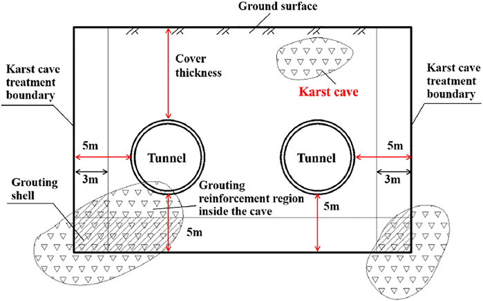
FIGURE 11. Karst cave treatment scope.
For karst caves and fissures located below the groundwater table, the cement-sodium-silicate two-shot slurry can be used for grouting reinforcement at 3 m inside the bottom and side boundaries of the treatment range to form a grouting wall and reduce the slurry loss. Cement slurry is used for grouting in the rest caves and fractured limestone. The used cement-sodium-silicate two-shot grouting material parameters are as follows: the volume ratio of the cement to sodium-silicate is C: S = 1(0.5–1); the concentration of sodium-silicate is 35Bé; the modulus m = 2.4–2.8; the water-cement ratio of cement slurry is 1:1 or 1:1.2; the grouting pressure is controlled at 0.3–0.6 MPa. Karst caves are divided into filled, semi-filled, and unfilled caves. The filled caves are mainly filled with cohesive soil and gravel, and the filling is relatively dense. For karst caves of different filling types and sizes, the specific treatment techniques are formulated as follows (Figure 12):
1) For fully-filled karst caves that need to be treated: Pressurized grouting is used for filling and reinforcement. The grouting material adopts cement slurry with the water-cement ratio of 1:1 or 1:1.2.
2) For unfilled karst caves and semi-filled karst caves: If the height of the karst cave is ≤ 1 m, then directly use 1:1 or 1:1.2 cement slurry for pressurized grouting; if 1 m < the cave diameter ≤4 m, then use sand blasting first, and then, grouting reinforcement method is adopted.
3) For extra-large unfilled caves with diameters> 4 m: Crushed stones (5–10 ram) are thrown into the caves first and then conduct grouting reinforcement. Usually, two boreholes are drilled (approximately 0.6 m) near the initial borehole during the process of filling stones. The centers of the two boreholes must be on the same line as the center of the initial borehole. The two sling holes can be used as vent holes for each other.
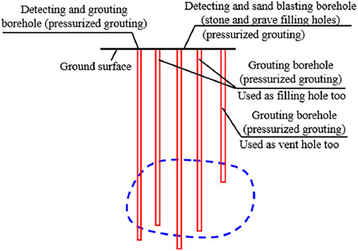
FIGURE 12. Karst cave treatment measurements.
Grouting boreholes are drilled in the surrounding rock that shields tunneling through the limestone. Taking 22.5° above the upper right of the segmental capping block as an example, it roughly reflects the cross-sectional distribution of the added grouting holes. According to the construction schedule of the segmental linings, determine the segment that needs to add grouting holes and the number and positions of the grouting holes. Conduct underground grouting using inert slurry with harmless properties, a short initial setting time, and a small and controllable diffusion scope. Multi-step grouting is performed with a small amount of slurry each time.
After shield tunneling, the secondary grouting (cement-sodium-silicate two-shot grouting slurry) is used to seal the water circumferential around the segmental lining in time to isolate the water from the rear positions. On the premise of not damaging the shield tail brush, the secondary circumferential hoop grouting position should be as close to the shield tail as possible, and the specific location should be about five segmental rings away from the shield tail (Figure 13). The proportion of the grouting slurry for the secondary circumferential hoop grouting should consider the fact that the water inflow at the back of the segmental lining is intense. Thus, the setting time of the grouting should be limited to about 10 s. The grouting pressure should be larger than the current water pressure by 2–3 bar so that the grout has a certain spreading ability, and it will not have a great disturbance on the surrounding soil and grouting body. In Jinan Metro Line R1, the secondary grouting uses a cement-sodium-silicate two-shot grouting slurry. The slurry ratio is as follows: cement slurry (component A) uses 42.5 ordinary Portland cement with a water-cement ratio of 1:1; sodium-silicate (component B) uses 1:1.5 with 35 Baume degree solution and water.
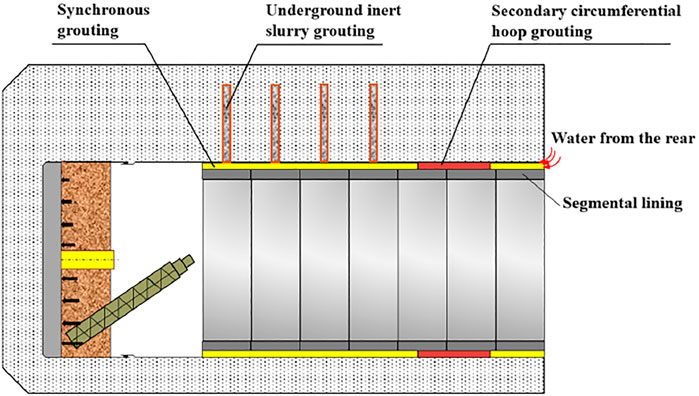
FIGURE 13. Secondary circumferential hoop grouting at the shield tail to prevent water inrush.
To realize safe and efficient shield tunneling in highly fractured karst and water-rich conditions, in addition to grouting and reinforcement of karst caves and surrounding rocks, it is also necessary to carry out optimization control for excavation.
To ensure the continued stability of the earth pressure and reasonably control the advance rate simultaneously, the tunneling speed should not be too slow. The advance rate in the limestone section is usually maintained at 15–20 mm/min. The comparison before and after the tunneling parameters adjustment is shown in Table 2:
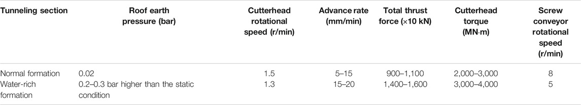
TABLE 2. Optimal tunneling parameters in the karst and fissure water-bearing limestone section.
Combining the tunneling methods in similar strata at Guangzhou and Shenzhen (China), the methods of adjusting the tunneling parameters, using the pressure holding system of the shield machine to inject ameliorant such as bentonite into the excavation cabin, and maintaining the excavation cabin to a low soil pressure state were applied. Therefore, it employs the Samson pressure holding system of the shield machine to inject industrial gas into the earth cabin and keeps the roof pressure larger than the water pressure at rest by 0.2–0.3 bar. In such a way, a dynamic air pressure balance is achieved. In addition, the air pressure to press bentonite into the cracks on the excavation contour to seal the fissure water is used (Figure 14).
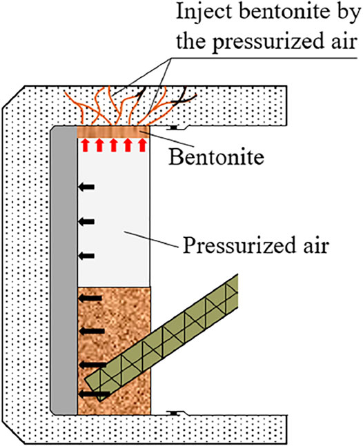
FIGURE 14. Schematic diagram of the air-pressure tunneling mode of the shield machine.
A large amount of muck restrains the slag outlet of the screw conveyor at the bottom. At the same time, high-density bentonite is injected into the screw conveyor to form a soil plugging effect, and pressurized air is used to replace the water in the cabin to alleviate the groundwater flow into the earth cabin. In the subsequent excavation process, the bentonite will be continuously substituted, but the rock powder continuously produced with the excavation will gradually replace the function of the bentonite, realizing continuous air-pressure tunneling mode.
Because the slag is mainly limestone chips with large porosity and high water permeability, a high-concentration bentonite solution additive (the specific gravity ratio of bentonite to water is 1:2) is injected into the cabin to replace the water storage to improve the fluidity of the muck. In addition, high molecular polymer solution (concentration 3‰) is added to increase the slag viscosity to ensure its plasticity, further reduce the spouting degree, and facilitate slag transportation.
A new type of soil modifier (i.e., mud cake dispersant) is joined to prevent “mud cakes” formation in the cutterhead and cabin. Serious “mud cakes” should be regularly cleaned, reducing the needed thrust and torque and prolonging the service life of the cutters.
After the karst cave and fissure water treatment complement, the core-drilling inspection was carried out in the treatment area to check the filling effect and compression strength, test whether the grouting body is continuous, and then conduct compression tests. The results show that the unconfined compressive strength is larger than 0.2 MPa. Engineering practice proves that the water flow and inrush on the tunnel face has been significantly alleviated when the shield machine reaches the grouted region. According to statistics, the water inflow on the tunnel face was about 4 m3/h before treatment, whereas the water inflow declined to only 0.3 m3/h after control, and the water inflow on the segmental lining was almost zero. From the perspective of the advance rate of the shield machine, the shield machine often needs to be drained and shut down for 2–3 days due to severe water inrush disasters in the past. Previously, the advance rate was severely restricted, about only 3 m/day without stopping. Whereas, the average advance rate reached 6 m/day after control. It can be seen that the treatment for karst caves and fissure water reduces the hazards of shield machine jamming and head-drops, improves construction efficiency and safety, and provides an economical and reliable method for the subsequent metro tunnels shield tunneling.
The shield machine started to enter the first limestone section when tunneling to the 35th ring on March 26, 2017. The shield machines on the left and right lines in the entire limestone section did not change the cutter, and the cutter wear was within the limited scope (i.e., 15 mm). After the two shield machines finished the first section excavation in the karst area, data statistics and analyses were carried out on the construction situation, and the summary is as follows (Table 3).
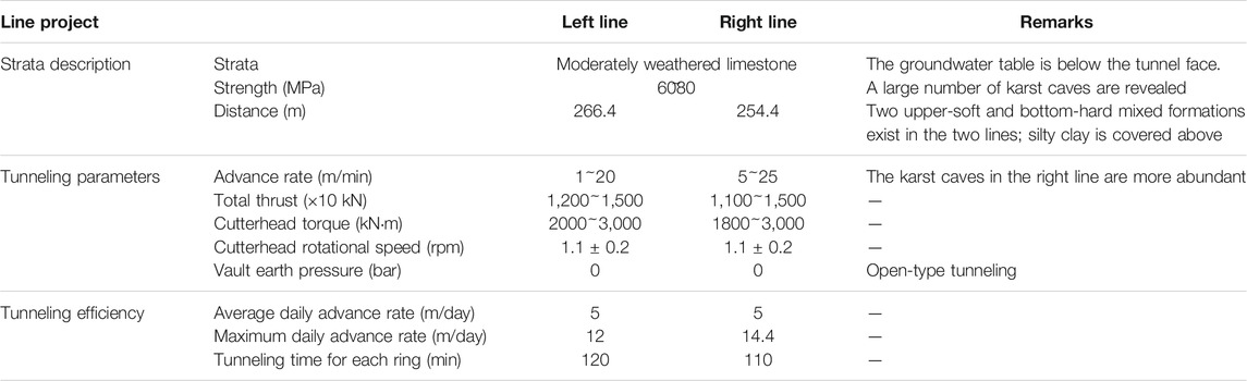
TABLE 3. Comparison of the shield tunneling performance on the left and right lines in the first section (air shaft-to-Dayangzhuang Station) at the karst area.
The control effect of karst and fissure water and shield tunneling efficiency show that the proposed multi-step combined control technology for karst and fissure water inrush disaster in this paper has achieved a good effect in shield tunneling.
At present, the detection and comprehensive disposal technologies for shield tunneling in karst and water-rich fissure zones are lacking. In addition, the treatment measures are usually blind. This study adopts advance prospecting using ahead geophysical prospecting and borehole drilling detection + multi-step grouting to prevent the groundwater + shield machine’s Samson air-pressurized tunneling model and other optimal tunneling technology. The pretreatment from the ground surface was also adopted in other projects (Table 4), and the measurements performed in this study are more refined. In addition, the technology of using shield protection slurry in the pressurized chamber opening for cutter inspection and change is also put forward.

TABLE 4. Cases of pretreatment from the ground surface.
Dewatering wells between the left and right tunnels in front of the shield machine to drain water and decline the groundwater level were built. Four dewatering wells are planned to be set up between the left and right tunnels. Their depth is 2 m below the tunnel bottom, the spacing is 6 m, and the diameter is 500 mm.
The location of the dewatering well is selected with reference to the horizontal position relationship between the limestone section tunnel and the pipelines, and the location of the dewatering well is adjusted according to the in situ situation to avoid the underground pipeline.
During shield tunneling through the karst and fissures-rich limestone strata, the water inflow is large (maximum to 600 m3/h), and it is a dynamic water environment. It is difficult for the traditional mud slurry protection method to maintain the earth pressure in the chamber. For example, when the shield tunneling machine on the left line of the air shaft-Dayangzhuang station section advanced to the 738th ring, it was about to leave the limestone, but the karst was developed strongly, and the water flows extremely severe. Three attempts were made to open the chamber under normal pressure for cutter inspection and replacement. However, they were unsuccessful due to the increasing water inflow at the tunnel surface.
To ensure the cutter inspection and replacement safety in the excavation chamber, shield protection slurry is used to protect the tunnel wall (Figure 15), and air-slurry replacement is used to maintain pressure balance for entering the cabin. The shield protection slurry has good workability, adhesion, etc. It is not easy to be diluted and carried away in the flowing water, has stable masque formation and good adhesion, and is a green and environmentally friendly material. In the case of a complex geological environment during shield construction, full-face sand, water-rich faulted and fracture zone, gravel pebble stratum, fractured rock formation, upper soft and lower hard rock stratum, the stable sealing and holding effect can meet the requirements of maintaining pressure when opening the chamber.
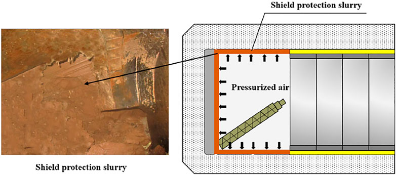
FIGURE 15. Shield protection slurry technology.
Water inrush disaster is easy to occur when shield tunneling through the highly fractured karst water-rich ground, especially in the dynamic water flow environment of the spring areas. To preserve the springs and ensure the shield tunneling safety and quality, a multi-step combined control method is presented to control the severe karst and fissure water inrush disaster. The proposed control technology was successfully applied in Jinan Metro Line R1. Specific conclusions are as follows:
1) Detailed geological exploration method combining the ahead geophysical prospecting and geological drilling is put forward to detect the karst and fissure water distribution. Ahead geophysical methods include geological radar, CT scanning, and high-density resistivity method. Accordingly, the groundwater flow paths were detected, which provided a basis for the subsequent karst and fissure water inrush control. The geophysical prospecting and geological drilling revealed 129 karst caves, among which 29, 65, and 35 karst caves distribute above, within, and below the tunnel, respectively. The size of the caves ranges from less than 1 m and more than 5 m. In addition, the karst and fissure underground water inflow reached 400–600 m³/h.
2) A multi-step combined grouting control technology is proposed to strengthen the surrounding rock and obstruct the water flow paths, including pretreatment from the ground surface, underground inert slurry grouting (using harmless and short initial setting time slurry with small and controllable diffusion range), and secondary circumferential hoop grouting at the shield tail.
3) In addition, optimal control technology for shield tunneling is put forward, including the optimization decision for tunneling parameters, the air pressure tunneling control model of the shield machine, and shield much improvement technology.
4) For the special dynamic water flowing environment in the spring area, cutter inspection and replacement technology using shield protection slurry in the pressurized chamber is developed. The popularization and application of this technology have been carried out successfully to ensure efficient and safe cutters replacement.
5) The inspection results show that the karst caves are densely filled after multi-step combined treatment, and the unconfined compressive strength of the filling body reaches larger than 0.2 MPa. The water inflow declined from the initial 4 m3/h before treatment to only 0.3 m3/h after control, and the water inflow on the segmental lining reduced to almost zero. The advance rate of the shield machine increased from previously only 3 m/day to almost 6 m/day after control.
The control effect of karst and fissure water and shield tunneling efficiency show that the proposed multi-step combined control technology for karst and fissure water inrush disaster in this paper has achieved a good effect in shield tunneling. The presented karst and fissure water inrush disaster control method is of great significance for tunneling in similar poor geological conditions.
The original contributions presented in the study are included in the article/Supplementary Material; further inquiries can be directed to the corresponding authors.
All authors listed have made a substantial, direct, and intellectual contribution to the work and approved it for publication.
This work was financially supported by the National Natural Science Foundation of China (grant nos. 52074258 and 41941018), the Natural Science Basic Research Program of Shaanxi Province (Shaanxi Coal and Chemical Industry Group Co., Ltd. Joint Fund Project, grant no. 2021JLM-06), and the Key Research and Development Project of Hubei Province (grant no. 2020BCB073).
KL was employed by China Railway 14th Bureau Group Co., Ltd. HS was employed by China Construction Civil Infrastructure Co., Ltd.
The remaining authors declare that the research was conducted in the absence of any commercial or financial relationships that could be construed as a potential conflict of interest.
All claims expressed in this article are solely those of the authors and do not necessarily represent those of their affiliated organizations or those of the publisher, the editors, and the reviewers. Any product that may be evaluated in this article, or claim that may be made by its manufacturer, is not guaranteed or endorsed by the publisher.
The authors would like to thank the China Railway 14th Bureau Group Co., Ltd. for the cooperation in the in situ control technology implement.
Carrière, S. D., Chalikakis, K., Sénéchal, G., Danquigny, C., and Emblanch, C. (2013). Combining Electrical Resistivity Tomography and Ground Penetrating Radar to Study Geological Structuring of Karst Unsaturated Zone. J. Appl. Geophys. 94 (4), 31–41. doi:10.1016/j.jappgeo.2013.03.014
China, (2021). China.com. Available at: http://news.china.com.cn/2021-07/22/content_77644855.htm.
Guan, Q. H., Li, F. L., Wang, A. Q., Feng, P., Tian, C. J., Chen, X. Q., et al. (2019). Hydrochemistry Chara-Cteristics and Evolution of Karst spring Groundwater System in Jinan. Carsologica Sinica 38 (5), 653–661.
Guo, Y. X., Zhang, Q. S., Xiao, F., Liu, R. T., Wang, Z. J., and Liu, Y. K. (2020). Grouting Rock Fractures under Condition of Flowing Water. Carbonate. Evaporite. 35 (3), 26. doi:10.1007/s13146-020-00619-z
Hu, Y. L., Wang, Q. J., Wang, H. B., Li, H. J., and Lin, X. D. (2009). Detection Effect of High Density Resistivity Method in Tunnel Exploration. Jilin Geology. 28 (12), 64–65.
Huang, F., Zhao, L., Ling, T., and Yang, X. (2017). Rock Mass Collapse Mechanism of Concealed Karst Cave beneath Deep Tunnel. Int. J. Rock Mech. Mining Sci. 91, 133–138. doi:10.1016/j.ijrmms.2016.11.017
Kang, Y., Geng, Z., Lu, L., Chen, L., Liu, X., Liu, B., et al. (2021). Compound Karst Cave Treatment and Waterproofing Strategy for EPB Shield Tunnelling in Karst Areas: A Case Study. Front. Earth Sci. 9, 761573. doi:10.3389/feart.2021.761573
Lee, S., and Moon, J.-S. (2020). Excessive Groundwater Inflow during TBM Tunneling in limestone Formation. Tunnelling Underground Space Tech. 96, 103217. doi:10.1016/j.tust.2019.103217
Li, B. (2021). Research on Application of Geological Radar in Karst Development Section of Yangshan Tunnel. China Energ. Environ. Prot. 43 (6), 144–243. doi:10.19389/j.cnki.1003-0506.2021.06.024
Li, L., Sun, S., Wang, J., Song, S., Fang, Z., and Zhang, M. (2020b). Development of Compound EPB Shield Model Test System for Studying the Water Inrushes in Karst Regions. Tunnelling Underground Space Tech. 101, 103404. doi:10.1016/j.tust.2020.103404
Li, L., Sun, S., Wang, J., Yang, W., Song, S., and Fang, Z. (2020c). Experimental Study of the Precursor Information of the Water Inrush in Shield Tunnels Due to the Proximity of a Water-Filled Cave. Int. J. Rock Mech. Mining Sci. 130, 104320. doi:10.1016/j.ijrmms.2020.104320
Li, S., Liu, B., Nie, L., Liu, Z., Tian, M., Wang, S., et al. (2015). Detecting and Monitoring of Water Inrush in Tunnels and Coal Mines Using Direct Current Resistivity Method: A Review. J. Rock Mech. Geotechnical Eng. 7, 469–478. doi:10.1016/j.jrmge.2015.06.004
Li, X., Ke, T., Wang, Y., Zhou, T., Li, D., Tong, F., et al. (2020a). Hydraulic Conductivity Behaviors of Karst Aquifer with Conduit-Fissure Geomaterials. Front. Earth Sci. 8, ID30. doi:10.3389/feart.2020.00030
Liu, B., Guo, Q., Liu, Z., Wang, C., Nie, L., Xu, X., et al. (2019). Comprehensive Ahead Prospecting for Hard Rock TBM Tunneling in Complex limestone Geology: A Case Study in Jilin, China. Tunnelling Underground Space Tech. 93, 103045. doi:10.1016/j.tust.2019.103045
Liu, F. L. (2018). Application Analysis of Shield Anti-gushing Technology for Metro in Water-Rich Stratum. China High-tech 14, 89–91. doi:10.13535/j.cnki.10-1507/n.2018.14.031
Liu, X., Hu, C., Liu, Q., and He, J. (2021). Grout Penetration Process Simulation and Grouting Parameters Analysis in Fractured Rock Mass Using Numerical Manifold Method. Eng. Anal. Boundary Elem. 123, 93–106. doi:10.1016/j.enganabound.2020.11.008
Niu, J. D., Sun, Y., Wang, B., Zhang, K. N., Huang, Y. H., Huang, S. W., et al. (2020). Grouting Treatment of Water and Mud Inrush in Fully Weathered Granite Tunnel: A Case Study. Geofluids 8838769, 18. doi:10.1155/2020/8838769
Qi, X. F., Wang, Y. S., Yang, L, Z., Liu, Z. Y., Wang, W., and Li, W. P. (2016). Time Lags Variance of Groundwater Level Response to Precipitation of Jinan Karst spring Watershed in Recent 50 Years. Carsologica Sinica 35 (4), 384–393.
Wang, S., Li, L., Cheng, S., Yang, J., Jin, H., Gao, S., et al. (2021). Study on an Improved Real-Time Monitoring and Fusion Prewarning Method for Water Inrush in Tunnels. Tunnelling Underground Space Tech. 112, 103884. doi:10.1016/j.tust.2021.103884
Wu, J., Li, S.-C., Xu, Z.-H., and Zhao, J. (2019). Determination of Required Rock Thickness to Resist Water and Mud Inrush from Karst Caves under Earthquake Action. Tunnelling Underground Space Tech. 85, 43–55. doi:10.1016/j.tust.2018.11.048
Xiong, F., Liu, X. R., Ran, Q., Li, B., Zhong, Z. L., Yang, Z. P., et al. (2020). Study on Instability Failure Mechanism of Karst Mountain with Deep and Large Fissures under the Mining-Fissure Water Coupling. J. China Coal Soc. (in Chinese), 1–15. doi:10.13225/j.cnki.jccs.2020.1690
Xue, Y., Kong, F., Li, S., Qiu, D., Su, M., Li, Z., et al. (2021). Water and Mud Inrush hazard in Underground Engineering: Genesis, Evolution and Prevention. Tunnelling Underground Space Tech. 114, 103987. doi:10.1016/j.tust.2021.103987
Yan, F., Qiu, W., Sun, K., Jiang, S., Huang, H., Hong, Y., et al. (2021). Investigation of a Large Ground Collapse, Water Inrush and Mud Outburst, and Countermeasures during Subway Excavation in Qingdao: A Case Study. Tunnelling Underground Space Tech. 117, 104127. doi:10.1016/j.tust.2021.104127
Yang, J., Zhang, C., Fu, J., Wang, S., Ou, X., and Xie, Y. (2020). Pre-grouting Reinforcement of Underwater Karst Area for Shield Tunneling Passing through Xiangjiang River in Changsha, China. Tunnelling Underground Space Tech. 100, 103380. doi:10.1016/j.tust.2020.103380
Zhang, C., Fu, J., Yang, J., Ou, X. F., Ou, X., Ye, X., et al. (2018b). Formulation and Performance of Grouting Materials for Underwater Shield Tunnel Construction in Karst Ground. Construction Building Mater. 187, 327–338. doi:10.1016/j.conbuildmat.2018.07.054
Zhang, K., Tannant, D. D., Zheng, W., Chen, S., and Tan, X. (2018a). Prediction of Karst for Tunnelling Using Fuzzy Assessment Combined with Geological Investigations. Tunnelling Underground Space Tech. 80, 64–77. doi:10.1016/j.tust.2018.06.009
Zhang, N., Shen, J. S., Zhou, A., and Arulrajah, A. (2018c). Tunneling Induced Geohazards in Mylonitic Rock Faults with Rich Groundwater: A Case Study in Guangzhou. Tunnelling Underground Space Tech. 74, 262–272. doi:10.1016/j.tust.2017.12.021
Keywords: karst and fissure water inrush disaster, shield tunneling, multi-step combined control technology, detailed geological exploration, multi-step grouting, tunneling optimization
Citation: Huang X, Li L, Zhang C, Liu B, Li K, Shi H and Jing B (2021) Multi-Step Combined Control Technology for Karst and Fissure Water Inrush Disaster During Shield Tunneling in Spring Areas. Front. Earth Sci. 9:795457. doi: 10.3389/feart.2021.795457
Received: 15 October 2021; Accepted: 29 October 2021;
Published: 02 December 2021.
Edited by:
Xiaodong Fu, Institute of Rock and Soil Mechanics (CAS), ChinaReviewed by:
Yalong Jiang, East China Jiaotong University, ChinaCopyright © 2021 Huang, Li, Zhang, Liu, Li, Shi and Jing. This is an open-access article distributed under the terms of the Creative Commons Attribution License (CC BY). The use, distribution or reproduction in other forums is permitted, provided the original author(s) and the copyright owner(s) are credited and that the original publication in this journal is cited, in accordance with accepted academic practice. No use, distribution or reproduction is permitted which does not comply with these terms.
*Correspondence: Chaofan Zhang, MTgyMjA4MDA3NTZAMTYzLmNvbQ==; Bin Liu, bGl1YmluQHdocnNtLmFjLmNu
Disclaimer: All claims expressed in this article are solely those of the authors and do not necessarily represent those of their affiliated organizations, or those of the publisher, the editors and the reviewers. Any product that may be evaluated in this article or claim that may be made by its manufacturer is not guaranteed or endorsed by the publisher.
Research integrity at Frontiers
Learn more about the work of our research integrity team to safeguard the quality of each article we publish.