
94% of researchers rate our articles as excellent or good
Learn more about the work of our research integrity team to safeguard the quality of each article we publish.
Find out more
ORIGINAL RESEARCH article
Front. Earth Sci., 16 February 2022
Sec. Geohazards and Georisks
Volume 9 - 2021 | https://doi.org/10.3389/feart.2021.792038
This article is part of the Research TopicMine Engineering Geological Disaster Forecasting, Monitoring, and PreventionView all 27 articles
The present study used PFC numerical software to examine the mechanical properties and fracture propagation characteristics of the fractured rock mass under coupling of heavy rainfall infiltration and mining unloading. Based on the engineering background of the Dexing mine, the pore water pressure is set to 0, 0.5, 1.0, 1.5, and 2.0 mpa, the true triaxial lateral unloading rate is 0.3 mpa/level and 0.6 mpa/level, and the water content state of rock is dry, natural, and saturated. Then, the true triaxial compression numerical simulation test is carried out, and the results showed that with the increase of the water content, the rock compaction stage increases, the elastic stage shortens, and the yield stage becomes more obvious. The faster the unloading rate is, the greater the influence on the rock strain is. After unloading, the stress jump point appears and the strain increase rate becomes larger, the volume of the rock increases and occurs as large s in the unloading direction, and finally it leads to severe brittle failure of the rock. With the increase of rock pore water pressure, the compressive strength and the peak strain of the rock decrease, and the pore water pressure accelerates the process of rock failure.
Since the 21st century, with the rapid development of modern mine technology, the scale and depth of mine rock mass projects have been continuing to grow rapidly. Large-scale high-steep rock slopes with a vertical depth of more than 400 m and a slope angle of more than 40° continue to emerge (Chen and Jing, 2016; Li X. S et al., 2021; Li et al., 2021). The long-term stability of high and steep rock slopes under complex geological and external disturbance environments has become a major problem for large-scale mines to convert from open-pit to underground mining. In China, the geological structure of Jiangxi Province is complex, and the long-term strong tectonic movement has fully developed the primary faults, joints, and fractures in the rock mass (Pu et al., 2019; Ji et al., 2020; Shuai, 2021; Liu et al., 2020a; Song et al., 2020; Du et al., 2021; Li et al., 2021a, Li et al., 2021b). Affected by open blasting, mechanical excavation, and weathering, a large number of secondary fissures have been generated inside the high-steep rock slope, which further aggravates the fracture and instability of the rock mass. In this area, the geological disasters induced by heavy rainfall are becoming more and more serious (Bai and Elsworth, 2020; Rutqvist and Stephansson, 2003; Lee and Cho, 2002; Li et al., 2020; Li L. K et al., 2021; Li et al., 2019; Li et al., 2021a; Li et al., 2021b; Li et al., 2021c; Song et al., 2021; Wang et al., 2021; Zhong et al., 2021). The mine slope rock mass has undergone the two-stage compound mining unloading effect after open-pit and underground mining. This nonsynchronous correspondence between time and space makes the failure mechanism of the slope under compound mining unloading more complicated. Therefore, in-depth research on the deformation and fracture characteristics of fractured rock masses under the coupling of heavy rainfall infiltration and mining unloading can ensure the safety and stability of mine slopes (Vandamme and Roegiers, 1990; Shao and Rudnicki, 2000; Tang et al., 2016; Liu et al., 2020b; Yao et al., 2020; Zhang et al., 2020; Deng et al., 2021; Liu et al., 2021; Zuo et al., 2021).
In the research of the fracture mechanism of the fractured rock mass, Giffith (1921) proposed the fracture criterion–energy criterion and the relationship between fracture toughness and crack size for brittle material crack size, in which the theory of fracture mechanics has been quickly applied and developed. However, this criterion cannot explain the singular solution of the stress at the crack tip of brittle materials. Griffith, (1924); Irwin (1957) revised Giffith’s theory to promote the further development of brittle rock linear elastic fracture mechanics. Erdogan and Sih (1963) proposed the theory of maximum stress resistance based on compound cracks in actual engineering, and they put forward the theory of strain energy density of mixed cracks in 1973. In addition, some scholars have proposed the failure criterion based on the tensile strain of brittle hard work. For example, Stacy (1981) believed that the prerequisite for rock fracture when the brittle hard rock cracked under compressive load was that the tensile strain of the brittle rock was greater than the maximum tensile strain threshold of the rock and derived the tensile strain judgment criterion. In the field of research on the fracture mechanism of the fractured rock mass under the coupling of hydraulic and mechanical effects, Kou et al. (2019) conducted a hydraulic coupling test on prefabricated 45° single-crack specimens, which showed that the peak strength of the specimen decreased with the increase of water pressure, and the deviator stress after the peak decreased. As the confining pressure increases, the peak strength increases, and the degree of post-peak strain-softening gradually increases. Valko and Economides (1994) and Souley et al. (2001) used the DMM model and CDM model to simulate the hydraulic fracturing process of rocks. Shao et al. (2005) and Yuan and Harrison (2006) used DMM/CDM and CDM/SM hybrid models to study the crack failure laws and permeability characteristics of the samples.
Nowadays, most scholars focus on the study of the crack criterion based on the maximum circumferential stress criterion (MTS) (Lin et al., 2018), the theory of the maximum energy release rate, and the theory of the strain energy density factor (S) (Liu et al., 2019; Jia-jun et al., 2020; Li et al., 2021d). Among them, the large-circumferential stress criterion is simple in form and can better predict the crack characteristics. But, this criterion ignores T-stress. For rock brittle materials, not only tensile failure but also shear failure affects the growth of cracks. The crack tip will also have N stress perpendicular to the crack surface (Zhao et al., 2012; Cheng and Zhou, 2015; Wei et al., 2017; Zhao et al., 2018; Guo et al., 2019; Liu et al., 2019; Li H. F et al., 2021; Wang and Zhao, 2021). Therefore, it is necessary to focus on studying the law of crack propagation after crack initiation. This research takes the open-pit to underground mining in the Dexing copper mine as the engineering background. Through geological investigations, on-site sampling, and indoor physical experiments, PFC numerical simulations were carried out for rocks under different water-bearing conditions, buried depths, fracture distribution, loading and unloading methods, and pore water pressure. In-depth analysis of the mechanical properties and crack propagation characteristics of the fractured rock mass of high and steep rock slopes was carried out under the coupling of heavy rainfall infiltration and mining unloading. It can provide necessary theoretical support for open-pit slope mining and underground surrounding rock support.
As shown in Figure 1A, the copper mine is located in Dexing City, Jiangxi Province, China. The copper factory mining area has the characteristics of mountainous microclimates such as warm climate, abundant rainfall, sufficient sunlight, large temperature difference between day and night, and long frost-free period. The working area is full of precipitation, and the annual average rainfall is 2250 mm. The rainy season is from March to July each year, and the precipitation accounts for about 70% of the annual precipitation. The average water period is from August to November, and the dry season is from December to February of the following year. In addition, the study area is a low mountain and hilly landform, with large undulations, high in the east and low in the west. The microtopography is mostly mountain valleys, forests, and farmland. Due to the artificial excavation of the mountain, an artificial slope with a height of about 548 m and a length of about 400 m is formed. The slope occurrence is 144°–152° in trend, 234°–242° inclination, 41°–42° inclination, and the copper mining area is about 4.8 square kilometers (red curve) (Figure 1(a1)). The artificial platform on the surface of the slope is covered by a 0.5–2.5 m thick artificial filling. The lower part of the slope is the mining area and transportation road. The strike and inclination of the fault have the characteristics of relaxation and wavy. The fault structure in the study area (H-H′ section) is well developed and has multiple phases. According to the occurrence and nature of the faults, the faults in the Huangniuqian slope area can be divided into EW faults, NNW faults, NWW faults, and NNE faults (Figure 1(a2)).
1) EW faults
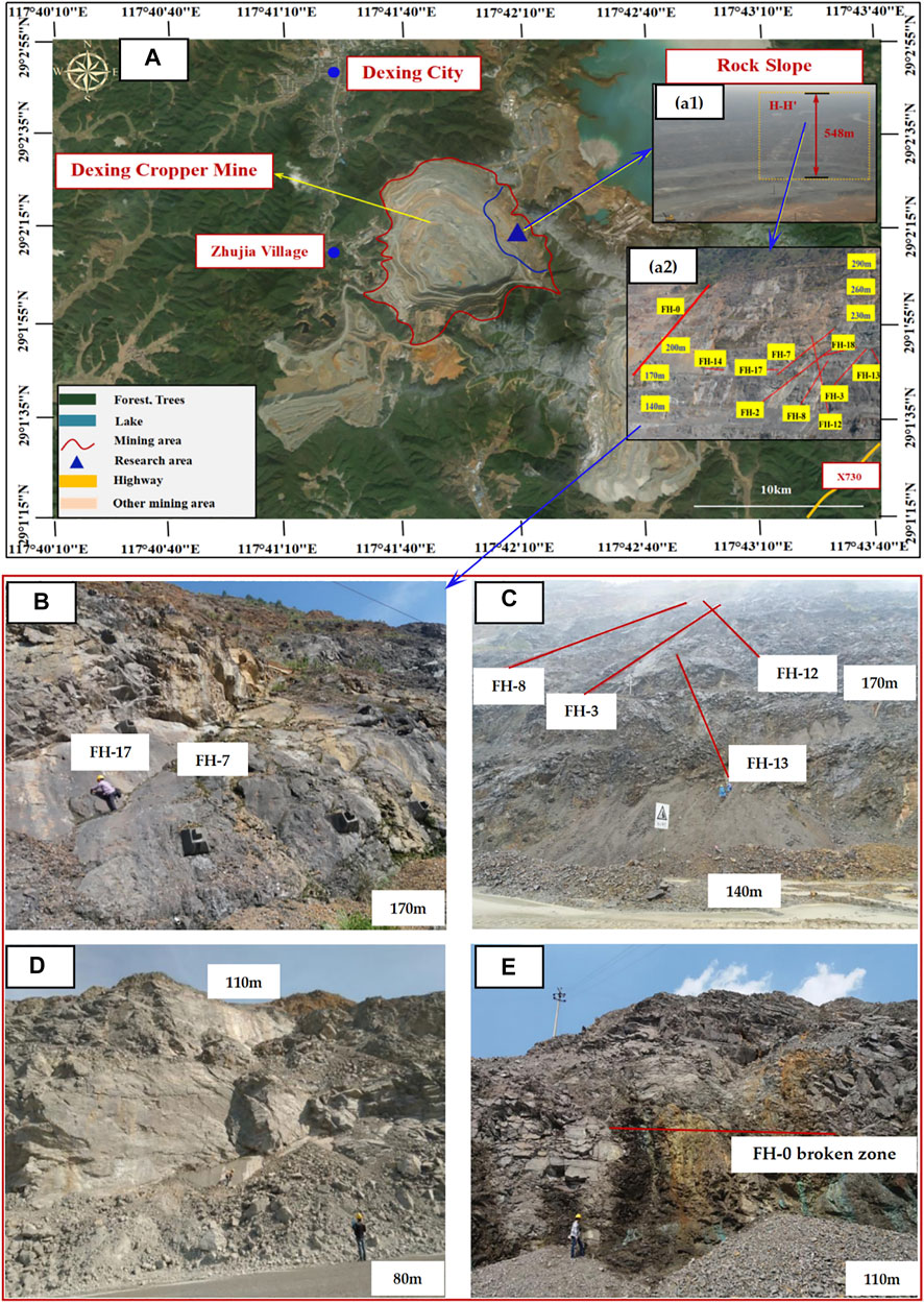
FIGURE 1. (A) Geographical location and topographic map of Dexing copper mine; (B) fault of FH-7 and FH-17; (C) fault of FH-3, FH-8, FH-12, and FH-13; (D) FH-14 fault (the lower part is an 80-m platform, and the upper part is a 110-m platform); (E) FH-0 regional fault broken zone.
As shown in Figure 1B, the EW fault is the main fault distributed on the Huangniuqian slope. It has different scales, longer extension, and characteristics of group appearance. There are 0.3–0.5 m thick compressive fault breccias and cements locally. It is the original rock cuttings and rock dust, and some cements have been schistosified. In addition, the larger faults in this group are FH-1 (regional fault), FH-2, and FH-7.
2) NNW faults
The NNW faults include FH-10, FH-11, FH-12, and FH-13. This group of faults obliquely intersects with the slope and is easily deformed and damaged by the wedge-shaped body with the EW-direction fault. For example, the 170 m platform slope is damaged by the wedge-shaped body cut by the FH-12 and FH-3 faults (Figure 1C).
3) NWW faults
As shown in Figure 1D, the strike of the NWW-trending fault is basically the same as that of the Huangniuqian pit slope, and it is one of the main factors affecting the stability of the Huangniuqian slope. The fault planes of this group are usually large and smooth, with an extension length of more than 100 m, and there are 20–30 m wide (densely developed joints) fracture zones on both sides.
4) NNE faults
The NNE faults mainly include FH-0, which is a regional fault (Figure 1E). Based on the results of joint statistics, it can be seen that the dominant joints developed in the Huangniuqian slope rock mass are basically consistent with the production and installation of the main faults. Therefore, this joint has a certain genetic relationship with the fault, and its developed dominant joint makes the rock mass of the slope mainly show a fragmented mosaic structure.
The test sample adopts the original mine slope (Figure 2A). Through on-site exploration and geological data analysis, several circular sampling regions (diameter about 2.00 m) with uniform texture and relatively complete rock mass were delineated at the Huangniuqian slope. In the process of drilling the surrounding rock of the rock mass stope, we took at least five relatively complete undisturbed samples from each sampling region (Figure 2B). As shown in Figures 2C,D, the obtained rock samples are processed in the laboratory into cylindrical standard specimens with a diameter and height of 50 mm × 100 mm or 50 mm × 25 mm, then the uniaxial and triaxial compression experiment of rock are carried out by GDS-VIS as shown in Figure 2E, and finally, the rock mechanical parameters at sampling point were obtained as shown in Table 1 below.
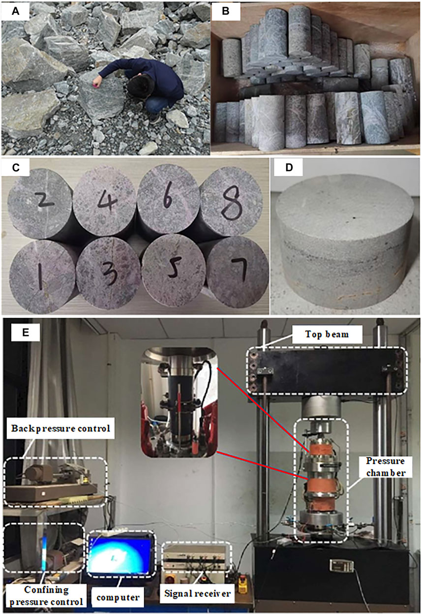
FIGURE 2. (A) On-site sampling; (B) on-site rock samples; (C) standard cylindrical specimen; (D) standard Brazil split specimen; (E) GDS-VIS uniaxial and triaxial compression machine.
At present, the study of joint crack propagation and penetration is mainly carried out under loading conditions, but in the study of the transition from open-pit to underground mining, it will cause a lot of unloading of the rock mass; moreover, the tensile stress may appear in the local area, and the damage to the rock mass is large. In this chapter, different loading and unloading schemes are used to carry out numerical simulation tests on the fractured rock mass to study its mechanical and failure characteristics.
The size of the true triaxial simulation specimen is 70 mm × 70 mm × 70 mm cube, and the parallel bond model is usually used when PFC simulates the high bond strength and the bending moment load of rock, while the plane joint model is used in the meso-structural plane (Shi et al., 2018). The fracture through the whole model in the strike direction and the model geometry are shown in Figure 3A.
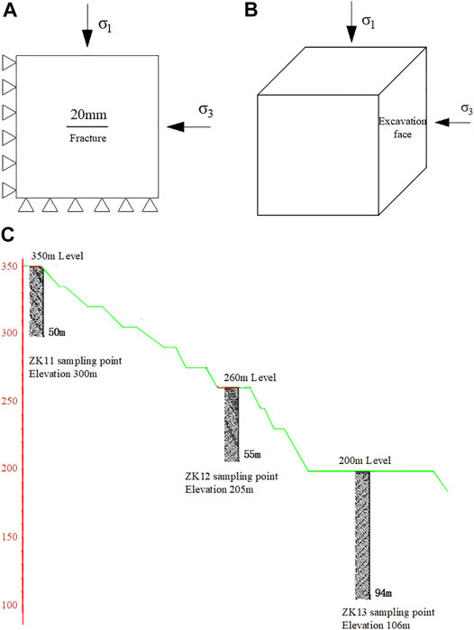
FIGURE 3. Model diagram. (A) Model geometry; (B) force diagram; (C) layout of sampling points in the fractured rock slope.
The excavation of the open-pit and underground chamber can be simplified as the plane strain problem. In general, the redistribution of stress increases in the vertical direction and decreases in the excavation direction (Huang et al., 2007; Liu and Li, 2020; Yang et al., 2021). In this research, it can be simplified as follows: stress is applied on the top face and the side face of the rock, and the other face is fixed. As shown in Figure 3B, σ1 is the stress on the top surface, and σ3 is the stress on the lateral excavation surface. The values of σ1 and σ3 are changed to simulate the stress change during excavation unloading. The loading and unloading schemes are divided into two groups as follows:
Plan A: Loading and unloading are carried out simultaneously; the first step is to pressurize at the same time to σ3 in the axial and horizontal directions, and the second step is to continue pressurizing in the axial direction until σ1 reaches the stable state; the first two steps are to simulate the stress state of rock in the rock stratum. The third step is to load and unload σ1 at 0.10 Mpa/level and σ3 at 0.05 Mpa/level which is to simulate the stress change process of the underground rock mass after the deep open pit mining is transferred to underground mining. In the fourth step, if the specimen is damaged before the unloading of the excavation face is completed, the lateral pressure is released immediately and the specimen is unloaded to 0 Mpa; if the unloading is completed and the specimen is not destroyed, the axial stress will continue to be applied until the specimen is completely destroyed.
Plan B: This plan is the contrast to plan A, where the axial stress is invariable and the lateral surface unload takes place. The simulation process is also divided into four steps. Compared with the unloading plan A, only the third step is different. The third step of plan B is that the axial stress will remain unchanged after reaching the initial in situ stress (preset value), the excavation surface will be unloaded at 0.15 Mpa/level, and proceed to the next level of unloading after equilibrium.
As shown in Figure 3C, the model parameters are determined by PFC calibration tests on the samples taken from three boreholes according to the depth of the high and steep rock slope in Dexing mine and the fractured rock mass in underground mining.
In order to compare the mechanical properties and failure characteristics of the rock mass with fractures under different unloading rates, two groups of different unloading conditions are set. Also, three sets of initial stress levels (σ1 and σ3 take three sets of values, that is, three drill-hole sampling points) are selected according to a representative set of pore water pressure measured in site and the distribution characteristics of typical fractured rock mass, under the condition that the specimen is saturated with water, the pore water pressure and the initial fracture distribution of the specimen are certain, and the unloading stress is adopted by plan A and plan B. Six groups of tests were carried out to systematically analyze the stress–strain curve trend, macro-mechanical parameters, and fracture evolution characteristics of the samples. The schedule of the loading and unloading comparison test is listed in Table 2.
The key of particle flow code (PFC) to simulate the mechanical behavior of materials is to generate the initial model (Zhang et al., 2021; Xu and Xu, 2021; Wang et al., 2021). First, the PFC servo system is used to adjust the packing density, size, and contact precision of the model particles to the ideal state and make them in the state of force equilibrium (Tian et al., 2021; Sarfarazi et al., 2021). After the initial model is generated, in order to make the macroscopic and microscopic mechanical properties of the specimen correspond to each other, the calibration test is carried out according to the stress–strain curves of the specimen measured under uniaxial compression, and the microscopic parameters are adjusted repeatedly by PFC. The calibration curves of experiment and simulation are shown in Figure 4.
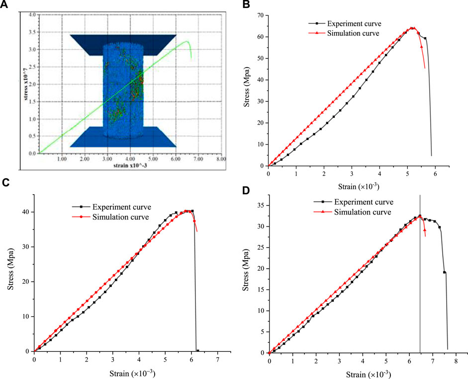
FIGURE 4. Calibration curve of the specimen. (A) PFC calibration model; (B) calibration curves of dry specimens; (C) calibration curves of natural specimens; and (D) calibration curve of the saturated specimen.
Through calibration, the final determination of the dry, natural, and saturated specimen PFC microscopic parameters is listed in Table 3.
As shown in Figure 5 below, Figures 5A–C show the deformation characteristics of the rock mass under excavation at different depths under the condition of single fracture. The axial stress σ1 and horizontal stress σ3 take three sets of values, respectively, for loading and unloading. Phase I is the loading and unloading at the same time, axial loading and unloading in the horizontal direction, which is the third and most important step of plan A, and Phase II is the lateral unloading complete and continuing loading in the axial direction, which is step four in plan A. Figure 5D is a comparison of three sets of values obtained under different conditions.
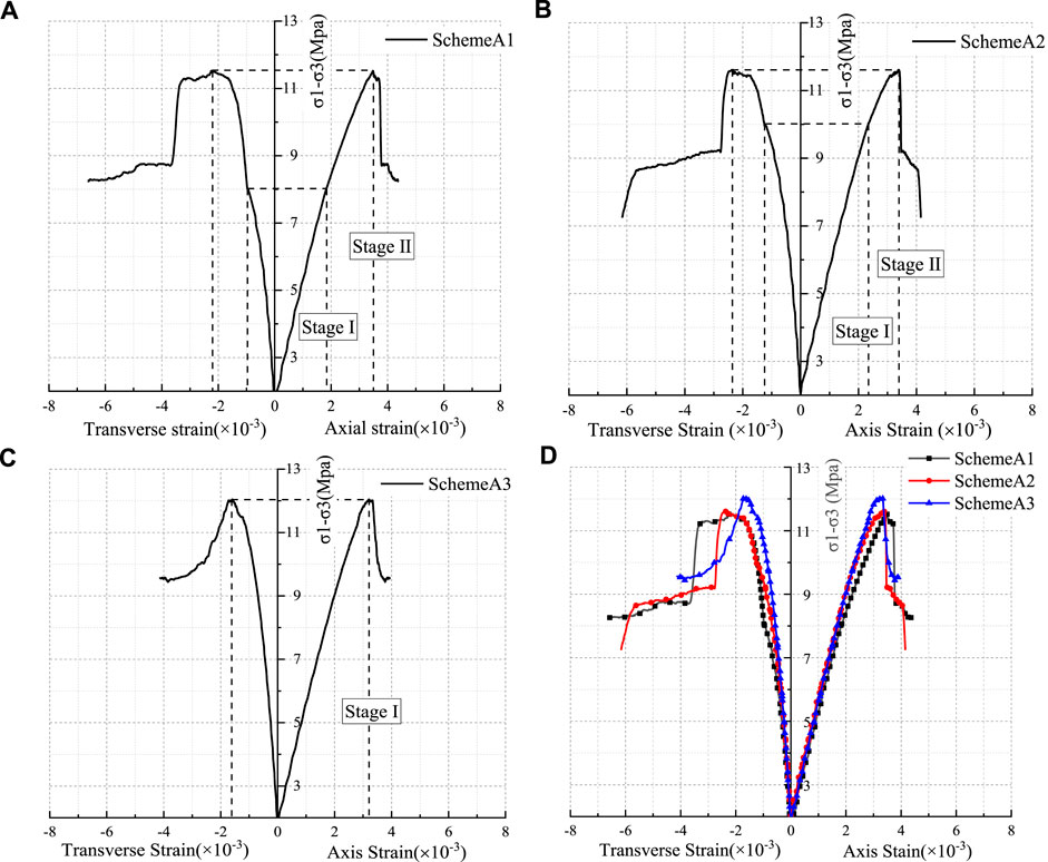
FIGURE 5. Deformation characteristics of the rock mass under different depth and plan A. (A) Loading scheme A1; (B) loading scheme A2; (C) loading scheme A3; and (D) comparative curves.
The typical stress–strain curve from Figure 5 shows that the larger the initial in situ stress (that is, the larger the value of σ1 and σ3), the smaller the peak axial strain from 3.48 to 3.21‰ and the lower the ductility of rock mass and the more brittle failure, as shown in Figure 5C. The specimen has been destroyed before Stage I is completed, which indicates that the surrounding rock may be destroyed before the unloading of the excavation face is completed during the deep excavation of underground mining. According to the post-peak curve, the process of axial stress decreases from the peak strength to the residual strength, the axial strain σ1 is small, and the larger the in situ stress is, the smaller the axial strain is during the drop process. It shows that the brittleness is more obvious with the increase of mining depth. The failure of the fractured rock mass is accelerated by the excavation of open face. In the loading and unloading test, the failure of the specimen in the axial loading test is mainly due to compression deformation, and the failure of the specimen in the unloading test is mainly due to the strong dilatancy along the unloading direction.
Figure 6 shows the deformation characteristics of the rock mass under excavation at different depths under the condition of plan B.
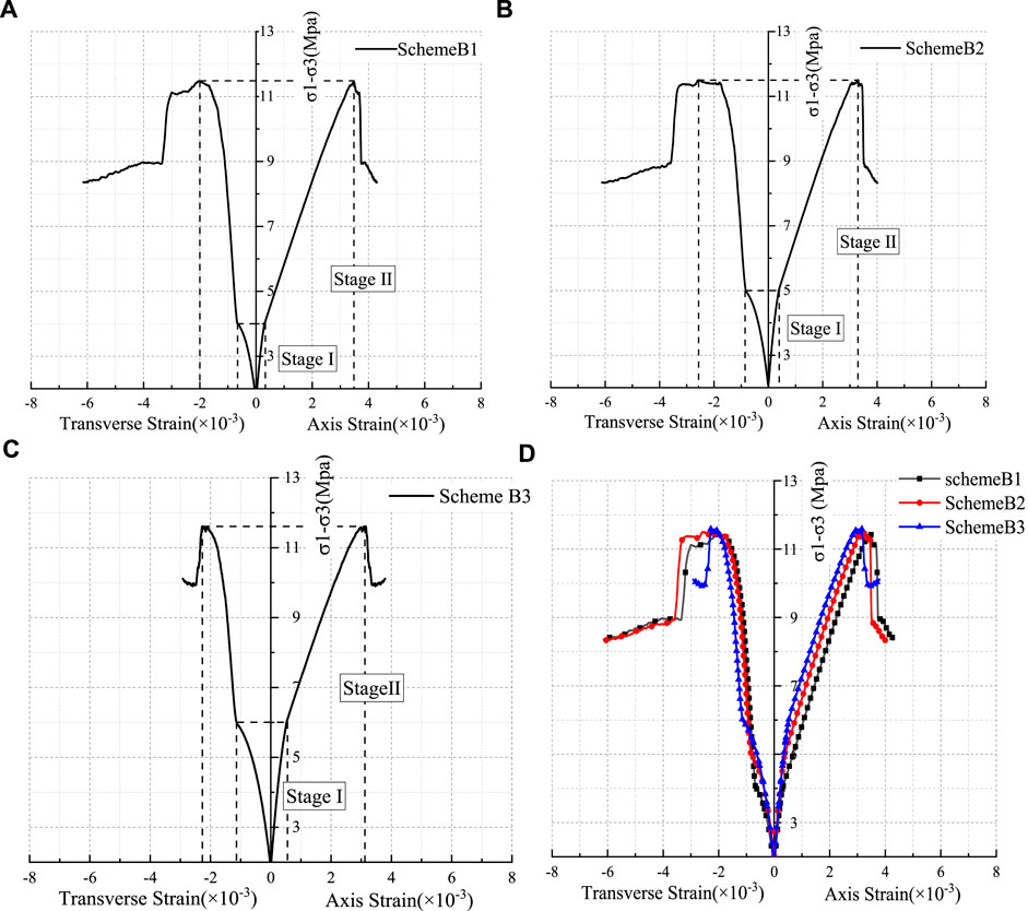
FIGURE 6. Deformation characteristics of the rock mass with different depth and plan B. (A) Loading scheme B1; (B) loading scheme B2; (C) loading scheme B3; and (D) comparison curves.
The typical stress–strain curve from Figure 6 shows that the deeper the fractured rock mass is, on the basis of the same mining technology, the longer the unloading time of rock mass is. But once unloading is completed, the increase of stress is larger, and the rock mass will reach the peak strength more quickly.
It can be obtained from the comparative analysis of plan A and plan B that the faster the unloading rate is, the greater the influence is on the axial and transverse strain of the rock mass. When the unloading is completed, there will be a stress jump point and the increasing rate will be faster. The results show that the specimen deforms strongly in the unloading direction, and the dilatancy and the brittle failure are obvious.
The simulation results of fracture propagation of the specimen under plan A and the sketch drawings are shown in Figures 7A,B. As can be seen from the drawings, the length of the preformed fracture is 20 mm, and the secondary airfoil-type tension cracks appear at the tip of the precast cracks. Because of the long precast cracks, a crack also appears in the middle of the precast cracks and extends toward the unloading surface; however, the airfoil cracks at both ends extend to the upper left and the lower right corner of the specimen, and tensile (red fracture in the simulation result) failure and shear failure (green fracture in the simulation result) occur during the crack propagation. Moreover, bond-tensile failure occurs earlier than shear failure, and the total amount of tensile failure is greater than that of shear failure. The crack near the excavation unloading surface expands more, and the crack in the middle of the precast fracture continues to expand to the right and has a tendency to run through, and the damage of the adjacent excavation unloading surface is more obvious. The final specimen was cut through by 20 mm cracks and airfoil tensile cracks. The specimen was completely destroyed, reached the peak stress, and lost the load-bearing capacity.
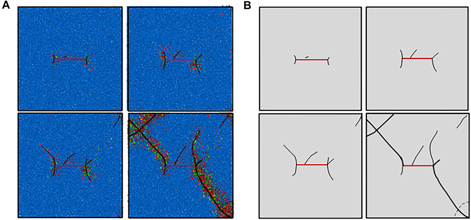
FIGURE 7. Sample simulation and sketch under loading plan A. (A) Simulation diagram of loading plan A; (B) sketch of the fracture.
The simulation results of fracture propagation under plan B and the sketch drawings are shown in Figures 8A,B.
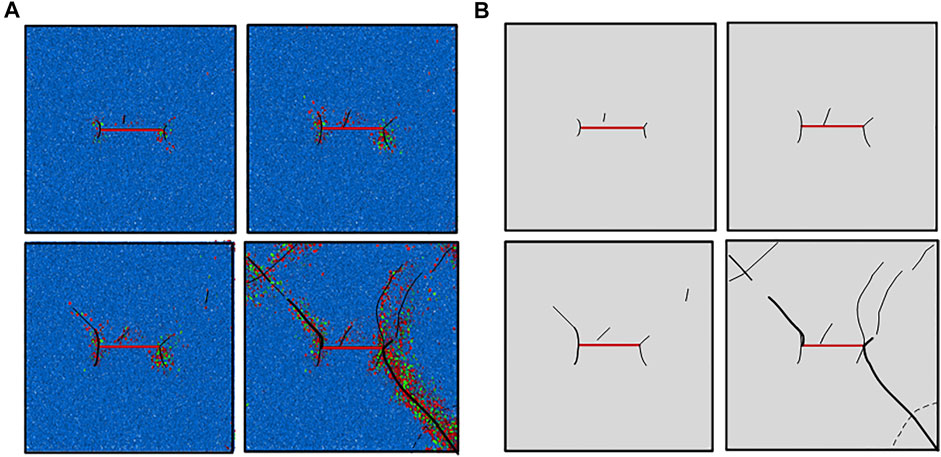
FIGURE 8. Sample simulation and sketch under loading plan B. (A) Simulation diagram of loading plan B; (B) sketch of the fracture.
The fracture characteristics of specimens under plan A and plan B are compared. The fracture trend of specimens is similar; the secondary airfoil-type tension cracks appear at the tip of the preformed cracks, and the small cracks appear in the middle of the preformed cracks. The cracks on both ends extend to the upper left corner and lower right corner of the specimen. But under the condition of plan B, the initial bonding fracture appears earlier, and the crack near the excavation unloading surface expands more. The crack is more concentrated, and the upper right part of the specimen has a bifurcated crack along the precast crack and has a tendency of penetrating with the upper right corner of the specimen. The failure of the unloading surface near excavation is more severe.
Figures 9A–C show the stress–strain curve of cracked specimens in dry, natural, and saturated conditions under loading and unloading plan A2, with stage I showing simultaneous loading and unloading and stage Ⅱ is the unloading complete and the axial continuous loading stage. Figure 9D shows the stress–strain curves of three groups of specimens.
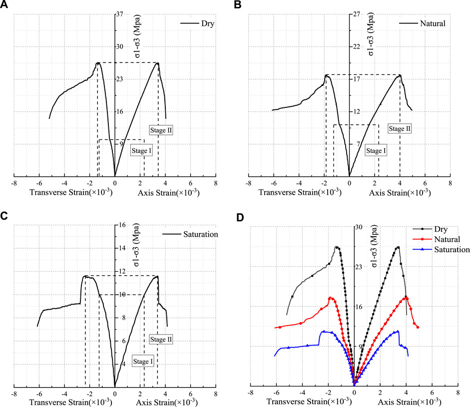
FIGURE 9. Specimen stress–strain curve under different water content. (A) Dry curve; (B) natural curve; (C) saturation curve; and (D) comparative curves.
In Figure 9, the stress–strain curve shows that when the moisture content of the specimen increases, the compressive strength and the elastic modulus decrease and the transverse peak strain increases. For example, when the water content increased from 1.12 to 4.85%, the compressive strength decreased from 17.65 to 11.59 Mpa, the elastic modulus decreased from 3.39 to 2.46 Gpa, and the transverse peak strain increased from 0.00188 to 0.00235. The decrease of compressive strength is about 56.33%, the decrease of elastic modulus is about 63.45%, and the increase of transverse peak strain is about 40.85%.
The mechanical properties and deformation characteristics of the specimen with different moisture content have the same tendency, and when the water content increases, the compressive strength and the elastic modulus of the specimen decrease. In this test, the dry specimen shows linear elastic change before reaching the peak strength, and the stress drop rate is faster after reaching the peak strength, and the brittleness of the specimen is obvious. According to the stress–strain curve, the higher the water content is, the longer the compaction stage, the shorter the elastic stage, and the more obvious the yield of the specimen are.
As shown in Figure 10 below, the results of the simulation and the sketch of the fracture propagation of the cracked specimen under plan A2 under dry, natural, and saturated conditions show that the generation and propagation of the cracks in the three specimens are similar. The secondary airfoil-shaped cracks appear at both ends of the precast cracks, and the small cracks appear in the middle of the precast cracks and extend toward the unloading surface. The airfoil cracks at both ends extend to the upper left and the lower right corner of the specimen. In the process of fracture propagation, both tensile failure and shear failure occur, and bond tensile failure occurs earlier than shear failure, and the total amount of tensile failure is greater than that of shear failure. The main failure mode of rock is tensile failure, while shear failure is subsidiary.
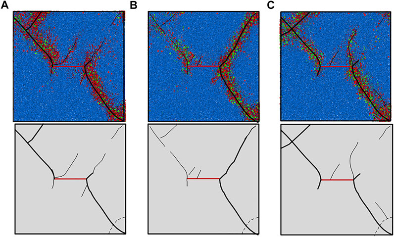
FIGURE 10. Simulation results and sketch of specimens under different water content after loading. (A) Dry; (B) natural; (C) saturation.
The brittle failure characteristics of dry specimen are more obvious than those of natural and saturated specimens, and the number of bond tensile failure is the most. In the natural state, the right part of the specimen is damaged more severely near the unloading surface, resulting in larger and deeper cracks, and generates more cracks and more complicated damage in the saturated state.
Figure 11A shows the specimen stress–strain curve under pore water pressure of 0.5 Mpa, and Figure 11B shows the stress–strain curve of cracked specimens at 0.5, 1.0, 1.5, and 2.0 Mpa under loading and unloading scheme A2.
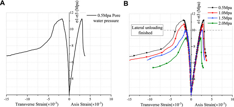
FIGURE 11. Stress–strain curve under different pore water pressure conditions. (A) Pore water pressure of 0.5 Mpa; (B) comparative curves.
From Figure 11, the stress–strain curve shows that the compressive strength and peak strain of the specimen decrease when the pore water pressure increases. For example, when the pore water pressure increased from 1.0 to 1.5 Mpa, the compressive strength decreased from 10.75 to 10.04 Mpa, and the peak strain decreased from 0.00289 to 0.00271. For the overall test of pore water pressure from 0.5 to 2.0 Mpa, the compressive strength and peak strain decreased by about 19.38 and 22.85%, respectively. When the pore water pressure is 0.5 Mpa, the elastic modulus of the sample is 2.82 Gpa, and when the pore water pressure is increased to 2.0 Mpa, the elastic modulus of the sample decreases to 2.40 Gpa, and the elastic modulus of the whole sample decreases to 14.89%.
Under different pore water pressure conditions, the mechanical properties and deformation characteristics of the stress–strain curve are similar—when the pore water pressure increases, the compressive strength decreases and the peak strain decreases, but the elastic modulus does not change much.
Figure 12 shows the simulation results and the sketch of the fracture propagation of the fractured specimen under pore water pressures of 0.5, 1.0, 1.5, and 2.0 mpa. It can be seen from the drawing, under the conditions of four kinds of pore pressure, the crack initiation and propagation of the specimen are similar. The secondary airfoil-type tensile cracks appear at both ends of the preformed crack, and the small cracks appear in the middle of the preformed crack and extend to the unloading surface. The airfoil cracks at both ends extend to the upper left and the lower right corner of the specimen. In the process of fracture propagation, both tensile failure and shear failure occur, and bond tensile failure occurs earlier than shear failure, and the total amount of tensile failure is greater than that of shear failure. The main failure mode of rock is tensile failure, while shear failure is subsidiary.
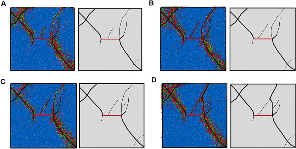
FIGURE 12. Simulation results and sketch of specimens under different pore water pressures. (A) 0.5 Mpa pore water pressure; (B) 1.0 Mpa pore water pressure; (C) 1.5 Mpa water pressure; and (D) 2.0 Mpa water pressure.
With the increase of pore water pressure, the failure of the specimen becomes more severe, such as the crack in the middle of the preformed crack, which spreads to the right side and passes through the main crack in the right side of the preformed crack. There are more and more cracks in the right part near the unloading surface, and the distribution of the cracks is more complex. The pore water pressure softens the rock material and causes stress concentration. The increase of pore water pressure accelerates the failure of rock.
The influence of pore water pressure on the fractured rock mass is analyzed as follows: the stress concentration phenomenon is easily formed between the micro-cracks and the particles by water pressure, and there is the phenomenon of hydraulic fracturing, which promotes the development of the crack of the specimen, and finally makes the micro-cracks gradually run through to form macro-failure. Because of this effect of the pore water pressure on the rock, the macroscopic mechanical properties of rock in the coupling state weaken obviously.
In the present study, several kinds of specimens with different water content, different loading plan, and different pore water pressure were tested by true triaxial numerical simulation tests. The mechanical properties and fracture propagation characteristics of the fractured rock mass under coupling of heavy rainfall infiltration and mining unloading are analyzed. The specific conclusions are as follows:
1) The faster the unloading rate is, the greater the influence on the rock strain is. After unloading, the stress jump point appears and the strain increase rate becomes larger, the volume of the rock increased and occurs as large deform in the unloading direction, and finally it leads to severe brittle failure of the rock.
2) The larger the initial in situ stress is, the smaller the peak strain, the lower the ductility, the faster the drop rate after the peak, and the more obvious the brittleness are, and the surrounding rock is easier to be damaged.
3) With the increase of the water content, the rock compaction stage increases, the elastic stage shortens, and the yield stage becomes more obvious. The failure mode begins with shear failure, followed by a combination of tensile and shear failure.
4) When the pore water pressure increases, the compressive strength and the peak strain of the specimen decrease, the pore water pressure accelerates the failure of the rock, and stress concentration and hydraulic fracturing are easily formed between micro-cracks and particles, which promotes the development of the crack.
The original contributions presented in the study are included in the article/Supplementary Material; further inquiries can be directed to the corresponding author.
All authors listed have made a substantial, direct, and intellectual contribution to the work and approved it for publication.
The research work was funded by the National Natural Science Foundation of China (NSFC) (Grant No. 41867033), State Key Laboratory of Safety and Health of Metal Mines Open Fund (Grant No. zdsys 2019-005), and China Postdoctoral Science Foundation Program (Grant No. 2019M650144).
MW was employed by Yunnan Phosphating Group Co. LTD.
XL was employed by Sinosteel Maanshan General Institute of Mining Research Co. LTD.
The remaining authors declare that the research was conducted in the absence of any commercial or financial relationships that could be construed as a potential conflict of interest.
All claims expressed in this article are solely those of the authors and do not necessarily represent those of their affiliated organizations, or those of the publisher, the editors, and the reviewers. Any product that may be evaluated in this article, or claim that may be made by its manufacturer, is not guaranteed or endorsed by the publisher.
Bai, M., and Elsworth, D. (2020). Coupled Processes in Subsurface Deformation, Flow, and transport[M]. Reston, VA: American Society of Civil Engineers
Chen, C., and Jing, B. X. (2016). Progress and Trend of the Theoretical Research and Practice of the Covering Layers of Open-Pit to Underground. Mod. mining 2, 5–10. doi:10.3969/j.issn.1674-6082.2016.02.002
Cheng, H., and Zhou, X. (2015). A Multi-Dimensional Space Method for Dynamic Cracks Problems Using Implicit Time Scheme in the Framework of the Extended Finite Element Method. Int. J. Damage Mech. 24 (6), 859–890. doi:10.1177/1056789514555149
Deng, W. X., Yang, T. H., Liu, F. Y., Li, H., Yang, Y. D., and Liu, Y. (2021). Study of Geometric Parameters Spatial Variability of Outcrops in Thin-Layered Rock Mass of Yanshan Iron Open-Pit Mine. Metal mine. 2, 139–145. doi:10.19614/j.cnki.jsks.202102021
Du, J., Chen, J., Pu, Y., Jiang, D., Chen, L., and Zhang, Y. (2021). Risk Assessment of Dynamic Disasters in Deep Coal Mines Based on Multi-Source, Multi-Parameter Indexes, and Engineering Application. Process Saf. Environ. Prot. 155, 575–586. doi:10.1016/j.psep.2021.09.034
Erdogan, F., and Sih, G. C. (1963). On the Crack Extension in Plates Under Plane Loading and Transverse Shear. Transaction ASME, J. Basic Eng. 85 (4), 519–525. doi:10.1115/1.365689910.1115/1.3656897
Griffith, A. A. (1921). VI. The Phenomena of Rupture and Flow in Solids. Phil. Trans. R. Soc. Lond. A. 221 (587), 163–198. doi:10.1098/rsta.1921.0006
Griffith, A. A. (1924). The Theory of rupture[C]. Denver, Colo: First International Congress for Applied Mechanics, 55–63
Guo, K. L., Yang, L., Sheng, X. C., Mei, J., Li, B. X., Zhang, B., et al. (2019). Fracture Mechanical Behavior and AE Characteristics of Rock-like Material Containing 3-D Crack under Hydro-Mechanical Coupling. Rock Soil Mech. 40 (11), 4380. doi:10.16285/j.rsm.2018.2052
Huang, D., Hunag, R. Q., and Wang, J. X. (2007). Contrastive Analysis of Stability of Block in Large Underground Caverns under Conditions of Excavation and Unloading. Chin. J. Rock Mech. Eng. 26 (S2), 4115–4122. CNKI:SUN:YSLX.0.2007-S2-077
Irwin, G. R. (1957). Analysis of Stresses and Strains Near the End of a Crack Traversing a Plate. Transaction ASME, J. Appl. Mech. 24, 361–364. doi:10.1115/1.4011547
Jia-jun, Z., Zhi-Jun, Z., and Cheng-zhi, P. (2020). Development and Application of a Hydraulic Loading Test System that Provides Continuous and Stable Hydraulic Pressure. Front. Earth Sci. 8, 1–7. doi:10.3389/feart.2020.00077
Jiang, P., Li, J., Zuo, S., Cui, X. Z., and Zhang, D. J. (2020). Ecological Retaining Wall for High-Steep Slopes: A Case Study in the Ji-Lai Expressway, Eastern China. Adv. Civil Eng. 2020 (2), 1–13. doi:10.3963/j.issn.1001-487X.2020.02.001
Kou, M., Liu, X., Tang, S., and Wang, Y. (2019). 3-D X-ray Computed Tomography on Failure Characteristics of Rock-like Materials under Coupled Hydro-Mechanical Loading. Theor. Appl. Fracture Mech. 104, 102396. doi:10.1016/j.tafmec.2019.102396
Lee, H. S., and Cho, T. F. (2002). Hydraulic Characteristics of Rough Fractures in Linear Flow Under Normal and Shear Load. Rock Mech. Rock Eng. 35 (4), 299–318. doi:10.1007/s00603-002-0028-y
Li, J., Chen, S. X., Yu, F., Jiang, L. F., and Dai, Z. J. (2020). Discussion on Mechanism of Reinforcing High and Steep Slope with Prestressed Anchor Cable. Rock Soil Mech. 41 (2), 707–713. doi:10.16285/j.rsm.2019.0034
Li, H. F., Feng, P., and Zhang, S. (2021). Comprehensive Control of High and Steep Slope in North Slope of Fushun West Open-Pit Mine. Opencast Mining Technology. 36 (4), 83–86. doi:10.13235/j.cnki.ltcm.2021.04.022
Li, L. K., Zhu, W. C., Dai, F., Liu, X. G., and Deng, W. X. (2021). Modelling of Dagushan Open-Pit Mine Slope with One Hundred Million Degrees of Freedom and Associated Numerical Simulation with RFPA3D. Metal mine 2, 179–185. doi:10.19614/j.cnki.jsks.202102027
Li, X. S., Wang, Y. M., Yang, S., Xiong, J., and Zhao, K. (2021). Research Progress in the Mining Technology of the Slowly Inclined, Thin to Medium Thick Phosphate Rock Transition from Open-Pit to Underground Mine. Appl. Mathematics Nonlinear Sci. 6 (1), 319–334. doi:10.2478/amns.2021.2.00017
Li, X., Liu, Z., and Yang, S. (2021a). Similar Physical Modeling of Roof Stress and Subsidence in Room and Pillar Mining of a Gently Inclined Medium-Thick Phosphate Rock. Adv. civil Eng. 2021, 1–17. doi:10.1155/2021/6686981
Li, X., Peng, K., Peng, J., and Hou, D. (2021b). Experimental Investigation of Cyclic Wetting-Drying Effect on Mechanical Behavior of a Medium-Grained sandstone. Eng. Geology. 293, 106335. doi:10.1016/J.ENGGEO.2021.106335
Li, X., Peng, K., Peng, J., and Xu, H. (2021c). Effect of Cyclic Wetting-Drying Treatment on Strength and Failure Behavior of Two Quartz-Rich Sandstones under Direct Shear. Rock Mech. Rock Eng. 54, 5953–5960. doi:10.1007/s00603-021-02583-z
Li, X., Yang, S., Wang, Y., Nie, W., and Liu, Z. (2021d). Macro-micro Response Characteristics of Surrounding Rock and Overlying Strata Towards the Transition from Open-Pit to Underground Mining. Geofluids. 2021, 1–18. doi:10.1155/2021/5582218
Li, X. S., Wang, Y. M., Zhao, K., and Yang, S. (2019). Research Progress on the Key Problems in Transition from Open-Pit to Underground Mining for Metal Mines. Metal mine. 12, 12–20. doi:10.19614/j.cnki.jsks.201912002
Lin, Q., Cao, P., Wang, H., Cao, R., and Chalioris, C. (2018). An Experimental Study on Cracking Behavior of Precracked Sandstone Specimens Under Seepage Pressure. Adv. Civil Eng. 2018, 1–10. doi:10.1155/2018/4068918
Liu, S., Bai, J., Wang, X., Wang, G., Wu, B., Li, Y., et al. (2021). Study on the Stability of Coal Pillars Under the Disturbance of Repeated Mining in a Double-Roadway Layout System. Front. Earth Sci. 9, 1–19. doi:10.3389/feart.2021.754747
Liu, W., Zhang, X., Fan, J., Zuo, J., Zhang, Z., and Chen, J. (2020a). Study on the Mechanical Properties of Man-Made Salt Rock Samples with Impurities. J. Nat. Gas Sci. Eng. 84, 103683. doi:10.1016/j.jngse.2020.103683
Liu, W., Zhang, Z., Fan, J., Jiang, D., Li, Z., and Chen, J. (2020b). Research on Gas Leakage and Collapse in the Cavern Roof of Underground Natural Gas Storage in Thinly Bedded Salt Rocks. J. Energ. Storage. 31, 101669. doi:10.1016/j.est.2020.101669
Liu, X., Zhu, Z., and Liu, A. (2019). Permeability Characteristic and Failure Behavior of Filled Cracked Rock in the Triaxial Seepage experiment. Adv. Civil Eng. 2019, 1–12. doi:10.1155/2019/3591629
Liu, Z. F., and Li, X. S. (2020). Research Progress on Fracture Evolution of Fractured Rock Mass. Nonferrous Met. Sci. Eng. 11 (04), 77–81. doi:10.13264/j.cnki.ysjskx.2020.04.012
Pu, Y., Apel, D. B., Liu, V., and Mitri, H. (2019). Machine Learning Methods for Rockburst Prediction-State-Of-The-Art Review. Int. J. Mining Sci. Technology. 29 (4), 565–570. doi:10.1016/j.ijmst.2019.06.009
Rutqvist, J., and Stephansson, O. (2003). The Role of Hydromechanical Coupling in Fractured Rock Engineering. Hydrogeology J. 11 (1), 7–40. doi:10.1007/s10040-002-0241-5
Sarfarazi, V., Abharian, S., and Ghorbani, A. (2021). Physical Test and PFC Modelling of Rock Pillar Failure Containing Two Neighboring Joints and One Hole. Smart Structures Systems. 27, 123–137. doi:10.12989/sss.2021.27.1.123
Shao, J. F., and Rudnicki, J. W. (2000). A Microcrack-Based Continuous Damage Model for Brittle Geomaterials. Mech. Mater. 32 (10), 607–619. doi:10.1016/S0167-6636(00)00024-7
Shao, J. F., Zhou, H., and Chau, K. T. (2005). Coupling Between Anisotropic Damage and Permeability Variation in Brittle Rocks. Int. J. Numer. Anal. Meth. Geomech. 29, 1231–1247. doi:10.1002/nag.457
Shi, C., Zhang, Q., and Wang, S. N. (2018). Numerical Simulation Technology and Application with Particle Flow Code (PFC5.0) [M]. Beijing: China Architecture & Building Press
Shuai, B. (2021). Treatment Technology of Dangerous Rock Mass at High and Steep Slope. Sichuan Water Powe. 40 (1), 105–108. doi:10.3969/j.issn.1001-2184.2021.01.024
Song, C. R., Li, Z. B., and Zhang, Y. (2020). Experimental Study on Group Anchor Effect in Strongly Unloading Rock Mass of a High and Steep Slope. J. Yangtze River Scientific Res. Inst. 37 (10), 117–124. doi:10.11988/ckyyb.20190772
Song, Z. H., Li, X. F., Qi, F. F., and Liu, H. (2021). Analysis of the Triggering Factors for Dangerous rockfall Accident in Open Pit Mine. J. Guangxi Univ. (Natural Sci. Edition). 46 (1), 159–165. doi:10.13624/j.cnki.issn.1001-7445.2021.0159
Souley, M., Homand, F., Pepa, S., and Hoxha, D. (2001). Damage-Induced Permeability Changes in Granite: A Case Example at the URL in Canada. Int. J. Rock Mech. Mining Sci. 38, 297–310. doi:10.1016/S1365-1609(01)00002-8
Stacey, T. R. (1981). A Simple Extension Strain Criterion for Fracture of Brittle Rock. Int. J. Rock Mech. Mining Sci. Geomechanics Abstr. 18 (6), 469–474. doi:10.1016/0148-9062(81)90511-8
Tang, S. B., Bao, C. Y., and Liu, H. Y. (2017). Brittle Fracture of Rock Under Combined Tensile and Compressive Loading Conditions. Can. Geotech. J. 54 (1), 88–101. doi:10.1139/cgj-2016-0214
Tian, Y., Wu, Y., Li, H., Ren, B., and Wang, H. (2021). Earthquake Dynamic Failure Mechanism of Dangerous Rock Based on Dynamics and PFC3D. Front. Earth Sci. 9, 1–14. doi:10.3389/feart.2021.683193
Valkó, P., and Economides, M. J. (1994). Propagation of Hydraulically Induced Fractures-A Continuum Damage Mechanics Approach. Int. J. Rock Mech. Mining Sci. Geomechanics Abstr. 31 (3), 221–229. doi:10.1016/0148-9062(94)90466-9
Vandamme, L. M., and Roegiers, J.-C. (1990). Poroelasticity in Hydraulic Fracturing Simulators. J. Pet. Technology. 42, 1199–1203. doi:10.2118/16911-PA
Wang, T., and Zhao, R. H. (2021). Deformation Characteristics of Open-Pit Slope Affected by Excavation Loading. Saf. Coal Mines. 52 (2), 231–234. doi:10.13347/j.cnki.mkaq.2021.02.042
Wang, X., Xia, Z., Li, P., and Liu, H. (2021). Numerical Study on Strength and Failure Behavior of Rock with Composite Defects Under Uniaxial Compression. Energies. 14, 4418. doi:10.3390/en14154418
Wei, M.-D., Dai, F., Xu, N.-W., Liu, Y., and Zhao, T. (2017). Fracture Prediction of Rocks under Mode I and Mode II Loading Using the Generalized Maximum Tangential Strain Criterion. Eng. Fracture Mech. 186, 21–38. doi:10.1016/j.engfracmech.2017.09.026
Xu, Y.-r., and Xu, Y. (2021). Numerical Simulation of Direct Shear Test of Rockfill Based on Particle Breaking. Acta Geotech. 16, 3133–3144. doi:10.1007/s11440-021-01172-2
Yang, S., Li, X. S., Liu, Z. F., Geng, J. B., and Rao, Y. B. (2021). Research on Overlying Strata Destruction and Instability of Underground Mining Stope in Different Inclined Ore Body. Mining Res. Development. 41 (04), 32–37. doi:10.13827/j.cnki.kyyk.2021.04.007
Yao, Q., Zheng, C., Tang, C., Xu, Q., Chong, Z., and Li, X. (2020). Experimental Investigation of the Mechanical Failure Behavior of Coal Specimens with Water Intrusion. Front. Earth Sci. 7, 348. doi:10.3389/feart.2019.00348
Yuan, S. C., and Harrison, J. P. (2006). A Review of the State of the Art in Modelling Progressive Mechanical Breakdown and Associated Fluid Flow in Intact Heterogeneous Rocks. Int. J. Rock Mech. Mining Sci. 43, 1001–1022. doi:10.1016/j.ijrmms.2006.03.004
Zhang, G., Chen, G., Xu, Z., Yang, Y., and Lin, Z. (2020). Crack Failure Characteristics of Different Rocks under the Action of Frost Heaving of Fissure Water. Front. Earth Sci. 8, 1–11. doi:10.3389/feart.2020.00013
Zhang, Y., Shi, C., Zhang, Y., Yang, J., and Chen, X. (2021). Numerical Analysis of the Brittle-Ductile Transition of Deeply Buried Marble Using a Discrete Approach. Comp. Part. Mech. 8, 893–904. doi:10.1007/s40571-020-00375-w
Zhao, C., Zhang, R., Zhang, Q., Shi, Z., and Yu, S. (2018). Shear-flow Coupled Behavior of Artificial Joints with Sawtooth Asperities. Processes. 6 (9), 152. doi:10.3390/pr6090152
Zhao, Y.-l., Cao, P., Wang, W.-j., Wan, W., and Chen, R. (2012). Wing Crack Model Subjected to High Hydraulic Pressure and Far Field Stresses and its Numerical Simulation. J. Cent. South. Univ. Technol. 19 (2), 578–585. doi:10.1007/s11771-012-1042-1
Zhong, X. Y., Liu, B. W., Chen, J. B., Wang, Z. W., and Wang, Y. C. (2021). Deformation Features of Slope Excavation and Parameter Optimization of Soft-Rock Bedding Slope in Open-Pit Mine. Coal Eng. 53 (3), 151–155. doi:10.11799/ce202103030
Keywords: rainfall infiltration, mining unloading, fractured rock mass, fracture propagation characteristics, numerical simulation
Citation: Wang M, Li X, Yang S, Teng L, Chen Q and Jiang S (2022) Research on Deformation and Fracture Characteristics of the Fractured Rock Mass Under Coupling of Heavy Rainfall Infiltration and Mining Unloading. Front. Earth Sci. 9:792038. doi: 10.3389/feart.2021.792038
Received: 09 October 2021; Accepted: 23 December 2021;
Published: 16 February 2022.
Edited by:
Jie Chen, Chongqing University, ChinaReviewed by:
Chun Zhu, Hohai University, ChinaCopyright © 2022 Wang, Li, Yang, Teng, Chen and Jiang. This is an open-access article distributed under the terms of the Creative Commons Attribution License (CC BY). The use, distribution or reproduction in other forums is permitted, provided the original author(s) and the copyright owner(s) are credited and that the original publication in this journal is cited, in accordance with accepted academic practice. No use, distribution or reproduction is permitted which does not comply with these terms.
*Correspondence: Shun Yang, eWFuZ3NodW4wODIwQDE2My5jb20=
Disclaimer: All claims expressed in this article are solely those of the authors and do not necessarily represent those of their affiliated organizations, or those of the publisher, the editors and the reviewers. Any product that may be evaluated in this article or claim that may be made by its manufacturer is not guaranteed or endorsed by the publisher.
Research integrity at Frontiers

Learn more about the work of our research integrity team to safeguard the quality of each article we publish.