 Elena Scacchia
 Roberto Tinterri
 Fabiano Gamberi
95% of researchers rate our articles as excellent or good
Learn more about the work of our research integrity team to safeguard the quality of each article we publish.
Find out more
ORIGINAL RESEARCH article
Front. Earth Sci. , 10 January 2022
Sec. Sedimentology, Stratigraphy and Diagenesis
Volume 9 - 2021 | https://doi.org/10.3389/feart.2021.785164
This article is part of the Research Topic Source or Sink? Erosional and Depositional Signatures of Tectonic Activity in Deep-Sea Sedimentary Systems View all 15 articles
Overbank deposits provide a potentially valuable record of flows that have passed through a submarine channel. The architecture of overbank deposits has generally assumed to relate to autogenic processes related to channel construction. In previous models, which are largely based on passive margins, the distribution and geometry of these deposits is relatively simple, and hence generally predictable. Here, we show how the interaction of different flow types with the complex morphology on a highly-tectonically modified margin can profoundly affect overbank depositional processes, and hence also the resultant deposit geometry and architecture. Our case study is the Acquarone Fan, located in the intraslope Gioia Basin in the south-eastern Tyrrhenian Sea, whose topography is mainly controlled by the presence of the Acquarone structural ridge, which results in the confinement of the left south-west side of the channel-levee system. The research is carried out through analysis of multibeam bathymetric and high-resolution Chirp sub-bottom profiler data. Seven depositional units (Units I-VII) record the recent depositional history of the fan; their thickness has been mapped and their parent flow-types have been interpreted through their seismic response. According to unit thickness maps, two main patterns of deposition are recognized in the overbank area. Their depocenters coincide with different extensive sediment wave fields developed in specific tracts of the right levee and in the frontal splay area. We show that the location of the depocenters varies in time according to the prevalent flow-type and by its interaction with the surrounding seafloor topography and channel planform. We interpret that the lateral confinement of the channel by the structural high generates episodic rebound of the overspilling flow and the inversion of the channel asymmetry. The vertical stratification of the flow strongly influences the overbank deposition where the channel planform has a non-linear shape such as bends and knick-points. In particular, the vertical stratification influences the hydraulic jump size that conditions the amount of overspill and thus the location of overbank depocenters. This study highlights that variations in the sediment distribution and composition on the overbank can be related to the way different flows interact with tectonic setting.
Turbidity currents are one of the primary mechanisms for sediment transport to the deep-marine environment and their deposits represent the fundamental building blocks of submarine fans. During part of their path, turbidity currents flow within submarine channels, the principal conduits for the transport of sediment from the shelf to the basin floor (Mutti and Normark, 1991). When the thickness of the turbidity current is greater than the channel depth, the upper part of the flow can escape the channel’s confinement and relatively fine-grained sediment settles beyond the channel banks and built overbank wedges (Piper and Normark, 1983).
The internal architecture and the distribution of lithologies in submarine fans and their control on the distributions of reservoir properties is fundamental information for petroleum exploration and for the advancement of the techniques for Carbon Capture Storage (CCS). As a consequence, the overbank depositional setting has recently become the focus of growing attention, since thin-bedded turbidite layers composing overbank wedges can be extremely laterally continuous (Peakall et al., 2000; Hansen et al., 2015) and contain large sand volume. As an example, a net to gross value > 50% has been reported in the Cretaceous San Fernando slope channel system of the Rosario Formation in Mexico (Hansen et al., 2015). In addition, a knowledge of the processes inherent with turbidity current behaviour is fundamental for the study of the fate of pollutants, plastics and microplastics in the marine realm (Zhong and Peng, 2021). Notwithstanding these issues with important applied outcomes, many aspects, related to turbidity current behaviour in overspilling submarine channels, remain one of the least well understood sedimentary processes.
The trends of lateral decay of levee, sand bed thickness and sand percentage transverse to the channel are thought to be predictable, and to follow power law, logarithmic or exponential decay according to the regional slope (Birman et al., 2009; Kane et al., 2010; Nakajima and Kneller, 2013). On the contrary, downslope trends in sediment distribution are less constrained. In general, levee construction involves the progressive downflow loss of fine-grained material that results in the downslope thinning of overbank wedges and increase in their sand content (Hiscott et al., 1997; Posameinter and Kolla, 2003).
However, the seafloor morphology can affect the behaviour of a turbidity current in several ways: it can halt the flow or change its velocity and alter its pathway (Kneller, 1995; Patacci et al., 2015). Those changes leave a footprint in the sedimentation pattern and in the facies and lithology distribution in submarine fans and the predictivity of those simple models can be drastically altered. The response of turbidity currents to slope topography has been investigated through several case studies specifically concentrating on their final depositional sites, corresponding to terminal lobes (Pickering and Hiscott, 1985; Haughton, 1994; Amy et al., 2004; Remacha et al., 2005; Gamberi and Marani, 2008; Tinterri and Muzzi Magalhaes, 2011; Tinterri and Piazza, 2019) and confirmed by experiments (Kneller et al., 1991; Kneller, 1995; Haughton et al., 2004; Amy et al., 2005; Patacci et al., 2015; Howlett et al., 2019). In contrast, few studies so far have linked the development of the overbank area of leveed channels to seafloor topography (Tek et al., 2021).
Information about the variation of sediment distribution over time can be used to reconstruct changes in the flow proprieties. Such reconstructions can be valuable for comparison with the trends expected from the application of existing models. In addition, studies on the modern seafloor, tied to well-known morphological contexts of deposition, can be vital for unravelling the effects of seafloor topography on sedimentation. This approach is used in this study focused on the overbank wedges of the Acquarone Fan, a deep-sea fan located in the continental slope of the Gioia Basin in the southeastern Tyrrhenian Sea. The study area has a complex physiography, mainly controlled by the presence of the Acquarone structural ridge, which confines the south-west side of the channel-levee system.
The objectives of this work are: 1) integrate bathymetric and seismic data to characterize seafloor morphology and the stratigraphic architecture of the last 40 m of the sedimentary succession; 2) provide a detailed analysis of sediment thickness distribution on a submarine channel overbank area. The final purpose of our study is to investigate the effects of topographic features, resulting from tectonic processes, on overbank deposition. In particular, with the examination of overbank processes in a topographically complex slope, we aim at highlighting the divergence from the established models of overbank sedimentation in simple slope settings.
In general, our results expand our understanding of overbank flow processes and show that, particularly in active continental margin, many factors, mostly extrinsic to the turbidite system, contribute to the final fate of sediment within leveed channels.
The Acquarone Fan is located in the southern part of the Calabrian sector of the Gioia Basin, an intraslope basin in the southeastern Tyrrhenian Sea (Figure 1A). The Gioia Basin formed in response to the backarc extension associated with the Ionian-Calabrian subduction zone, which started in the Late Miocene (Fabbri et al., 1980; Gamberi and Marani, 2006). Since then, the Gioia Basin has been affected by major NE–SW, N–S, and E–W trending extensional faults (Fabbri et al., 1980; Casas et al., 2016). The Acquarone Fan developed in the depocenter of the Calabrian sector of the Gioia Basin, a semi-graben created by the past action of a NW-SE-trending, NE-dipping extensional fault (Figure 1C). Since the Middle Pleistocene, the physiography of the basin has been mainly controlled by the recent tectonic deformation, associated with high rates of vertical movement, also affecting the Sicilian and Calabrian mainland.
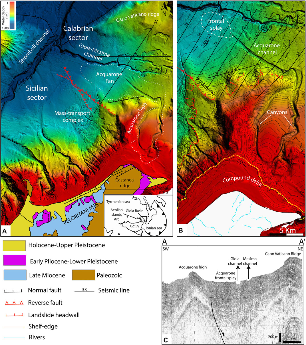
FIGURE 1. (A) Shaded relief map from multibeam bathymetric data of the Gioia Basin and geological map of north-eastern Sicily (Gamberi and Rovere, 2011). (B) Zoom of the study area (box in a) over a bathymetric map with 20 m contour and location of the available seismic lines. Two submarine canyons feed the Acquarone leveed channel and its frontal splay (dashed white line). (C) Strike airgun seismic profile (location in A) of the northern part of the Gioia Basin. The Acquarone frontal splay is between the Gioia-Mesima channel system and the Acquarone ridge.
The submarine expression of the high rates of uplift of the basin margin is particularly evident in the Sicilian sector, where seafloor instability resulted in an extensive mass-transport complex (Gamberi and Marani, 2006; Gamberi and Rovere, 2011; Rovere et al., 2014; Gamberi et al., 2019) (Figure 1A). In the Calabrian part of the basin, tectonic unrest is shown by the presence of structural ridges that are also affected by large collapses (Gamberi and Marani, 2006; Casas et al., 2016; Casalbore et al., 2019). The Acquarone Fan is bounded to the south by the Acquarone high, a structural ridge that represents the submarine continuation of the Castanea ridge (Figure 1A) (Gamberi and Rovere, 2011), an uplifting area (1.1 mm/y) on the Peloritani Mountains (Catalano and Di Stefano, 1997; Antonioli et al., 2006). Evidence of the recent tectonic activity is given by the presence of fluid escape features (pockmarks) at the seafloor in connection with a transpressive fault (Rovere et al., 2014) (Figure 1A). An extensional fault crosses the base of the Acquarone high with a W-E direction in a sector highly affected by mass-wasting processes (Gamberi et al., 2019) (Figures 1A,B). The Acquarone fan develops southward from the Gioia-Mesima channel, a tributary to the Stromboli channel (Figure 1A). The Gioia-Mesima channel has undergone a complex evolution a complex evolution shown by abandoned meanders incised by a straight course due to base level deepening associated with the erosion and deepening of the Stromboli valley (Gamberi and Marani, 2008; Gamberi et al., 2019). The Acquarone Fan develops in the ENE-dipping slope and reaches a water depth of 1,000 m. The fan is fed by two submarine canyons (Figure 1B). The eastern canyon-head is at a depth of 90 m on the shelf edge and is 2.8 km off the coast; the western canyon head is at depth of 120 m and 5.3 km off the coast. On land, a small subaerial drainage basin of about 13 km2 in the Paleozoic terrain of the Castanea ridge flanks the canyon head (Figure 1A). In these mountainous, tectonically active and uplifting catchments, rivers are incisional features with high gradient, torrential discharges and high sediment yield (Regione Siciliana, 2006). At present, the sediment load is ultimately deposited on the continental shelf where is interpreted to be resuspended by longshore currents and rearranged into an asymmetric compound delta (Figure 1B). The compound delta, in its apex position, is only 700 m from the shelf edge and is in front of the eastern canyon head.
Like the majority of submarine fans in tectonically active continental margins, the Acquarone Fan is a small turbiditic system: from the canyon head to the edge of the frontal splay it is 33 km long and is 8 km wide at the most. Its limited lateral extension is due to the topographic confinement caused by the Acquarone high to the south and the presence of the Gioia-Mesima canyon-channel system to the north.
The Acquarone channel is bounded to the south by the Acquarone high, which stands out for about 900 m from the surrounding seafloor. The Acquarone high confines the proximal tract of the channel-levee system to its west preventing the construction of a levee in the left channel side down to a depth of 810 m (Figure 2). Moreover, the presence of the Acquarone high has “forced” the channel to develop a bend that steers the channel pathway from the N–S direction of its proximal sector to the NW–SE pathway of its distal sector (Figures 1B, 2). Further downslope, the confinement gradually decreases resulting in a partially confined area which extends until a water depth of 880 m, where the channel-levee system is no longer confined (Figure 2). The Acquarone high also controls the distribution of mass-transport deposits (MTDs), since, according to the seafloor reflectivity, recent collapses occurred on its flanks (Figure 2) (Gamberi and Marani, 2008). The recent MTDs are localized in the Acquarone channel thalweg, downslope from the meander, and on the surface of the left levee in the partially confined area (Figure 2).
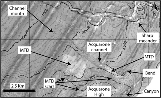
FIGURE 2. Sea floor reflectivity image of the Acquarone Fan and of the portion of the Gioia channel to the north, draped over a bathymetric map with 10 m contours. The floor of the Acquarone channel shows mainly a low backscatter, with high backscatter only near a slide deposit (MTD) at the base of a scar on the flank of the Acquarone High. The lobate sea floor mound with high backscatter south of the Acquarone channel represents accumulation of slope-waste deposits derived from the Acquarone High. The Gioia channel floor shows patches of high backscatter, indicating recent activity. (Modified from Gamberi and Marani, 2008).
The leveed Gioia-Mesima channel system limits the Acquarone Fan to the north and act as its base level (Figure 1A). Thus, the Acquarone Fan is an example of a transient fan, i.e. those fans that store part of the sediment but are connected to a deeper depositional area (Adeogba et al., 2005; Gamberi and Rovere, 2011). The distance between the Acquarone and the Gioia channels decreases downslope: the Gioia channel is 8 km far from the Acquarone channel bend and 3 km far from the Acquarone channel mouth (Figure 2). The interaction with other channels is one of the possible factors complicating thickness and sand distribution in external levees (Hansen et al., 2015). The Gioia–Mesima channel is principally characterized by erosional processes (Gamberi and Marani, 2008) as shown by an incision of about 80 m. Said incision is consistent with the erosional deepening of the Stromboli Slope Valley that lowered the base level of the Gioia-Mesima channel, which became strongly entrenched and straight (Figure 1A). Moreover, the overspilling clouds, flowing from east to west, preferentially deposit on the right-side of the Gioia-Mesima channel, and therefore the left overbank splay is exclusively alimented by the high-momentum spill-over process near a sharp channel meander (Figure 2) located 7 km far from the Acquarone channel bend (Gamberi and Marani, 2008). The sediment starvation of the left overbank splay of the Gioia-Mesima channel is confirmed by its low backscatter compared to the channel floor (Figure 2). All these observations suggest that the proximity of the Gioia-Mesima channel does not represents a bias for the quantification of the sedimentary budget on the Acquarone overbank area.
Multibeam bathymetric data and high-resolution seismic data, imaging the Acquarone Fan in its whole length, represent our primary dataset. The major part of the study area is covered by a digital high-resolution terrain model. The latter consists of a mosaic of multibeam data acquired during two surveys carried out in 2013 and 2014 (CAT13 and MARBEEP14 respectively) on board the R/V Urania with the multi-beam system Kongsberg EM710 (frequency 70–100 kHz). In general, given the frequency of the multibeam instruments and the depth range of the study area, the bathymetric data have a vertical resolution less than 0.5 m. The acquired data cover depths between 300 and 1,300 m and has been merged with the EMODnet Project bathymetric data available for the shallower areas. High resolution subbottom data consists of Chirp profiles, acquired in 2013 with the Chirp Benthos III technology (frequency 2–7 kHz). Vertical resolution of the seismic profiles is in the order of 0.5 m. The Chirp sections, spaced at about 2 km, cut perpendicularly the Acquarone Fan, from the leveed channel to the fan fringe (Figure 1B). The penetration of the Chirp profiles depends on the type of sediment, being inversely proportional to sediment grain size and compaction.
The multibeam bathymetric data was imported and analysed using the Global Mapper® software for the production of contour and slope maps, channel and levee longitudinal profiles and cross-sections of the sediment waves. Sediment wave wavelength is calculated as the distance between two consecutive troughs, whereas wave heights as the distance from the wave crest to a straight line connecting two consecutive troughs (Figure 3). Following Symons et al. (2016), the cross-sectional shape of a sediment wave was defined as upslope asymmetric, when the downslope limbs are longer and shallower (Figure 3). Accordingly, when the downslope and upslope limbs are even, sediment waves are classified as symmetric (Figure 3). The principal overspilling flow direction is assumed perpendicular to the local orientation of the sediment wave crests (Normark et al., 2002). In particular, for crescentic forms the flow direction is assumed to be parallel to the principal plane of curvature of the bedform, whereas for sinuous bedforms the flow direction is assumed to be at 90° from the line connecting to two subsequent inflections in the crest of the sediment wave (Figure 3).
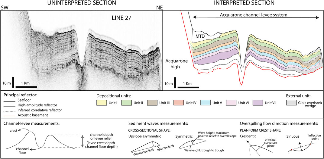
FIGURE 3. To the left the uninterpreted seismic section (location on Figure 1B), to the right the interpreted line drawing of the principal reflector that have been traced across the study area and the units comprised between them. At the bottom of the image, sketches about the methodologies applied for the measurements of channel-levee elements, sediment waves morphological parameters and overspilling flow direction.
The Chirp profiles allowed us to recognize seven units (I-VII) in the last 40 m of the sedimentary succession (Figure 3). The boundary of the units correspond to high-amplitude reflectors, which can be followed throughout the study area. Each unit consists therefore of a coherent set of turbidites deposited, during a specific time interval, by successive flows in the different environments of the Acquarone Fan. As such, our units correspond with depositional packages deposited during discrete time interval and have a chronostratigraphic meaning. Owing to the correlatability of the units throughout the study area, spatial variations in sedimentary processes can be observed, through seismic facies and thickness analysis. In particular, the thickness distribution of the units is represented in isopach maps, which are useful to pinpoint and visualize the successive phases of construction of the Acquarone Fan. Moreover, based on the reflection character in the subbottom profiles, we defined five acoustic facies. The spatial-temporal changes in facies distribution, reconstructed from the comparison of the detailed facies maps of the seven units, are the key for interpreting sedimentary processes.
Based on interpretation of the multibeam bathymetric data, the morphology of the depositional environments of the fan will be presented.
The Acquarone leveed channel has formed at the slope base, at a water depth of about 750 m, at the junction of the two tributary canyons in the upper slope (channel initiation in Figure 4A). The two canyons are confined within a depression that cuts the slope of the Acquarone High. The Acquarone channel exits the depression confinement and makes a wide westward turn taking up a NW course, perpendicular to the slope gradient. The channel has an average gradient of about 1°, but it displays several variations in gradient as shown by its long profile in Figure 4B. Also the channel depth, calculated as the relief of the levee crest with respect to the channel floor for each levee (Figure 3) shows large variations (the red line refers to the right levee and the light blue line to the left levee in Figure 4B). The deepest tract of the channel is in its confined part, where, in the bend, the channel depth increases reaching its maximum of almost 60 m (Section 1 in Figure 4B). The channel profile in the confined tract is affected by a recent MTD, whose topographic effect causes a drastic reduction in the channel height (Section 2 in Figure 4B). At the beginning of the partially confined area, the channel depth gradually decreases to 30 m (Section 3 in Figure 4B). The central tract of the channel profile has two knick-points, named KP1 and KP2, that are, respectively, 7 and 11 m high (Figure 4B). At KP1 the channel gradient halves abruptly, while the gradient difference in KP2 is less sharp (Figure 4C). Along the flat segments of the knick-points the channel depth increases (Sections 4–5 in Figures 4B,C). Knick-point initiation has been linked to different processes: channel avulsion (Deptuck et al., 2007), bend cutoff (Sylvester and Covault, 2016), internally generated within channels (Heijnen et al., 2020) or tectonics (Heiniö and Davies, 2007). In the Acquarone channel there is no evidence of channel avulsion and knick-points are located far from the bend. Also the internally generated origin has been excluded since it have been recognized in a prevalently erosional channel where turbidity currents originate knick-point far higher (about 20 m) and steeper (10°–30°) than the knick-points in the Acquarone channel (Heijnen et al., 2020). Accordingly with the interpretation of Gamberi et al. (2019), the origin of the knick-points in the Acquarone channel can most likely be ascribed to the tectonic framework. This thesis is supported by KP1 which represent the prosecution of an extensive fault that cross the base of the Acquarone High (Figure 4A). Moreover, the alternation of ramp and flat segments related to the channel profile is in phase with the gradient variation in the levee crest profiles (Figure 4C). This configuration shows that the topographic displacement is not localized in the knick-points, but it is laterally continuous and, therefore, conceivably connected to allogenic, tectonic processes.
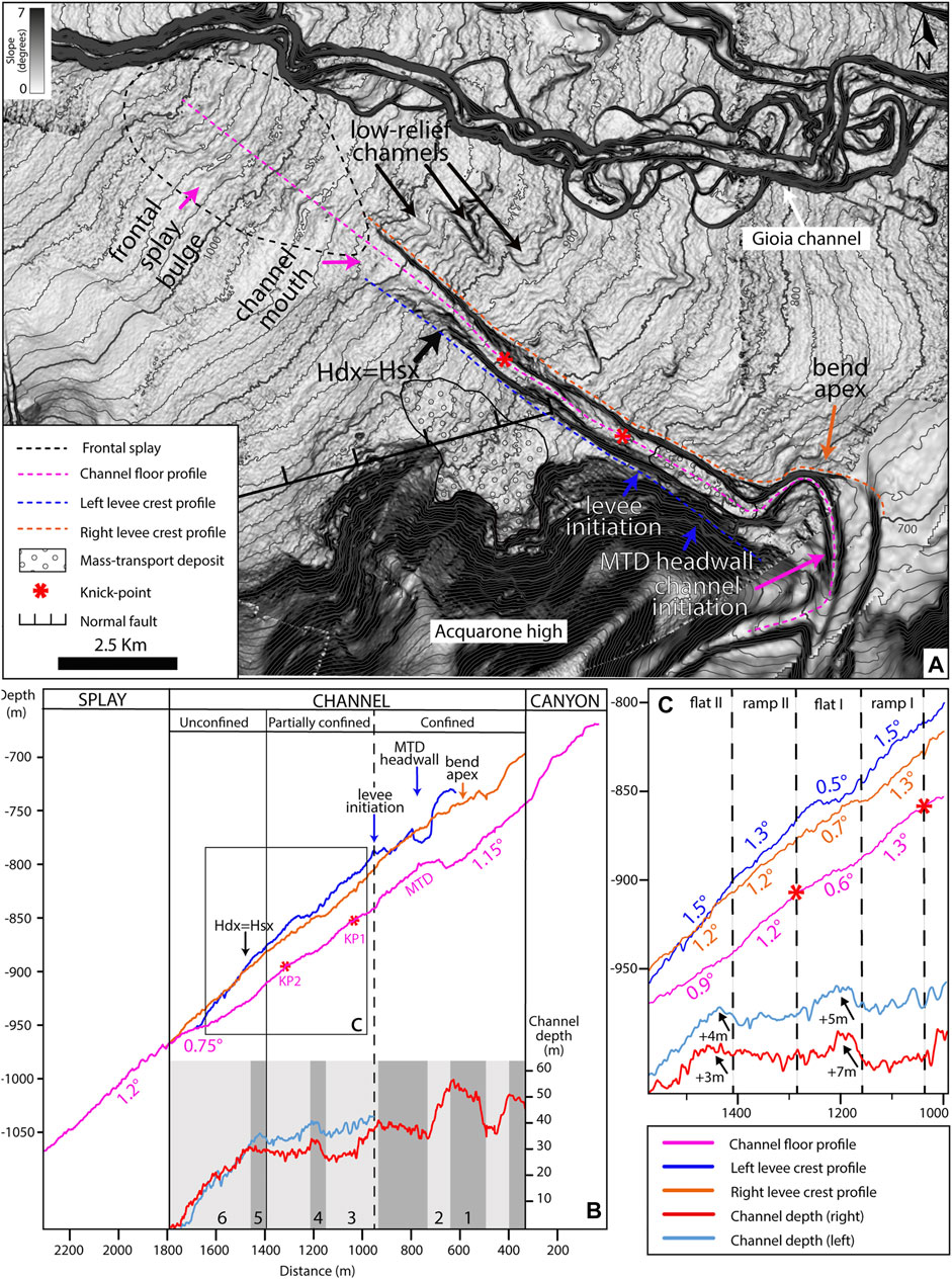
FIGURE 4. (A) Shaded relief map in BW colours that highlights the principal morphological features of the seafloor marked by arrows. (B) Acquarone channel talweg (pink), right levee (orange) and left levee (blue) longitudinal depth profiles. At the bottom, the channel relief referred to the right levee (red) and to the left levee (light blue), the dark grey sections mark where the channel depth tends to increase, while in light grey where it tends to decrease. (C) Zoom of the channel depth and longitudinal profiles in the central sector of the channel with the related slope values.
The right and left levees are very different in terms of their extension, relief and distribution of sediment waves. The left levee is 6 km long, it begins at a depth of 800 m, downslope from the Acquarone ridge slope and terminates at a depth of 950 m (Figure 4A). On the contrary, the right levee bounds the channel for its whole length, i.e. 14 km (Figure 4A). In its proximal tract, the left levee is about 15 m higher than the right one (Figure 4B). The difference between the relief of the two levees decreases downslope and, at the end of the confined tract, at a depth of 900 m, the two levees have the same height (Hdx = Hsx, in Figure 4). Beyond this point, the left levee has a lower relief than the right one (Figure 4B).
Extensive sediment wave fields develop in specific tracts of the right levee (Figure 5). According to the classification of Symons et al. (2016), based on wavelength and amplitude, they fall into the group of small-scale sediment waves (<300 m wavelength and <8 m wave height) but, at the small scale, the sediment waves have different dimensions and cross-sectional shapes resulting in highly different morphologies. They have been subdivided into different sediment wave fields, according to their wavelength, wave height and spreading direction, occupying different areas (Figures 5A,B): A) Bend area: the outer side of the bend on the right levee; B) Laterally confined area: a lobe-shaped area on the right-levee; C) Knick-points area: a triangular shaped area with upslope apex on the levee crest laterally to KP1 and termination at the end of the channel.
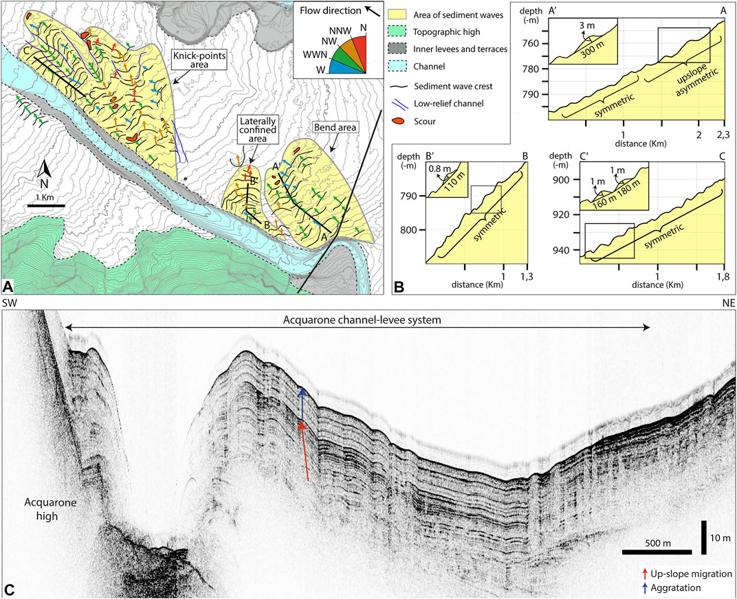
FIGURE 5. (A) Illustration of the three areas of sediment wave fields in the overbank area. For each sediment wave field. Flow direction arrows are coloured to highlight the flow diversions. (B) Bathymetric profiles perpendicular to the crest direction of the waves in the three areas. (C) Chirp line 33 cuts perpendicularly the channel-levee system in correspondence of the meander. In the proximal part of the outer levee it shows the upslope migration of the sediment waves, followed by a more aggradational behaviour.
The Bend area presents sediment waves spreading out from the outer side of the bend (Figure 5A). The crests are parallel to the bend suggesting that they were formed by the spreading of high-momentum spillover flows. In cross-section, they are upslope asymmetric, with amplitude and wavelength that reach a maximum of 3 and 300 m respectively; they become symmetrical, smaller and more closely spaced downslope, suggesting a rapid loss of momentum (Profile A-A′, Figure 5B). Moreover, the seismic line 33, that cross perpendicularly part of the bedfroms, highlights that the sediment waves in the Bend area show an initial slow up-slope migration followed by a more aggradational phase, with almost no change in trough and crest position (Profile A-A’, Figure 5B).
Further downslope, in the Laterally confined area, the second sediment wave train develops on the right levee (Figure 5A). The trend of the sediment waves crests indicates that, initially, the overbanking flows are parallel to the course of the channel, but they rapidly become orthogonal to the channel trend and follow the slope direction. They have a symmetrical profile and very low relief with an average wave height of 0.9 m and a wavelength of 140 m (Profile B-B’, Figure 5B).
In the Knick-points area, the third train of sediment waves trends subparallel/oblique to the channel axis (Figure 5A). The waves have a symmetrical cross-section and are regularly spaced with wavelength of 150 m, while their amplitude increases downslope from 0.5 m to a maximum of 2 m (Profile C-C’, Figure 5B). The crests have a sinuous planform; within a bedform row, the landward convex part of single bedforms are in phase and appear to form low-relief, 2–3 km-long channels, with NW-SE direction (Figure 4A).
The Acquarone channel dies out in the lower slope forming a frontal splay that has a NW-SE-trending main elongation axis and stretches the slope with a width of 5 km. It has an area of about 28 km2 and laterally and distally passes to a fan fringe area, which occupies most of the remaining slope. The frontal splay has its apex at a depth of 950 m, at the distal end of the channel left levee, and terminates at a depth of 1,070 m where the southern flank of the Gioia-Mesima channel is (Figure 4A). The apex of the fan is where the slope gradient increases, from 0.75° in the distal tract of the channel, to 1.20° (Figure 4B). Just beyond the channel mouth, the frontal splay has a convex cross-section (Figure 4A). Further downslope, the fan has a central bulge flanked by two slightly depressed areas (frontal splay bulge in Figure 4A).
Another sediment wave field occupies the Frontal splay area, a lobate area that occupies the whole surface of the frontal splay (Figure 6). In the Frontal splay area the sediment waves have an upslope asymmetric cross-section shape with wavelength of about 300 m and maximum height of 4, 6 m, which decreases moving away from the channel mouth (Profile D-D’, Figure 6). The wave crests have a general NE-SW orientation, and they are aligned roughly parallel with the main flow pathway. The crest directions are not perfectly parallel with each other showing a deflection in their orientation, highlighted by the coloured arrows in Figure 6.
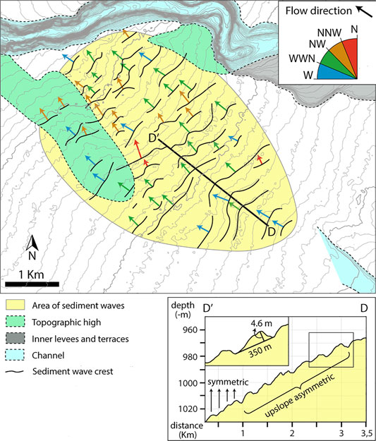
FIGURE 6. Illustration of the sediment wave field in the frontal splay area. Flow direction arrows are coloured to highlight the flow diversions. Bathymetric profile perpendicular to the crest direction of the waves.
The interpretation of the subbottom Chirp profiles allowed the recognition of five acoustic facies whose characteristics will be described in the following paragraph. A seismic characterization based on the distribution of the acoustic facies and their lithology interpretation is reported in the second paragraph of this chapter for each depositional environments.
Taking into account the presence or absence of reflections, the relative amplitude of reflections, the geometry of reflectors (parallel, irregular, etc.), five different acoustic facies have been distinguished. A brief description of the acoustic facies, comprehensive of their interpretation in terms of their most likely lithology and depositional environment, is reported in Table 1. The first word of the acoustic facies name describe, when the reflection are present, their geometry (parallel or irregular) while, when the reflections are absent, is labelled as transparent; the second word describe the strength of the acoustic reflection (high or low):
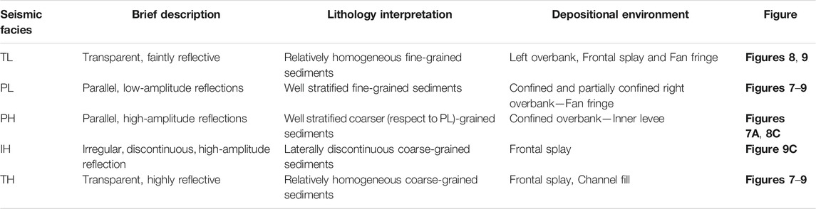
TABLE 1. Seismic facies recognized in the Acquarone Fan.
Transparent Low-reflectivity (TL): Intervals lacking coherent reflectors with faint reflectivity.
Parallel Low-reflectivity (PL) Parallel to subparallel, continuous to discontinuous, low-amplitude and high-frequency reflections.
Parallel High-reflectivity (PH) Parallel to subparallel, continuous to discontinuous, high-amplitude reflections and high-frequency reflections.
Irregular High-reflectivity (IH) Irregular, discontinuous, variably spaced, high-amplitude reflections.
Transparent High-reflectivity (TH) Intervals lacking coherent reflectors but highly reflective, commonly reducing the penetration of acoustic energy.
At a large scale, subsurface imaging reveals the typical components of channel-levee systems, with channel floor deposits and overbank wedges. The most part of the channel axis has a transparent, highly-reflective facies, suggestive of coarse-grained channel fill deposits (Figures 7, 8). The only exception occurs at the channel mouth where the coarse-grained sediments of the channel-axis infill are buried under a homogeneous fine-grained deposit (TL) (Figure 8C).

FIGURE 7. To the left the original subbottom Chirp profiles, to the right the subsurface drawing. The different units are marked with colours while the seismic facies with patterns. The acoustic basement is marked by the red line and the Gioia overbank wedge is grey. The seismic profiles are perpendicular to the channel-levee system where only the right-side overbank wedge is well built. Line 33 (A) cuts the Bend area; Line 31 (B) cuts the Laterally confined area.
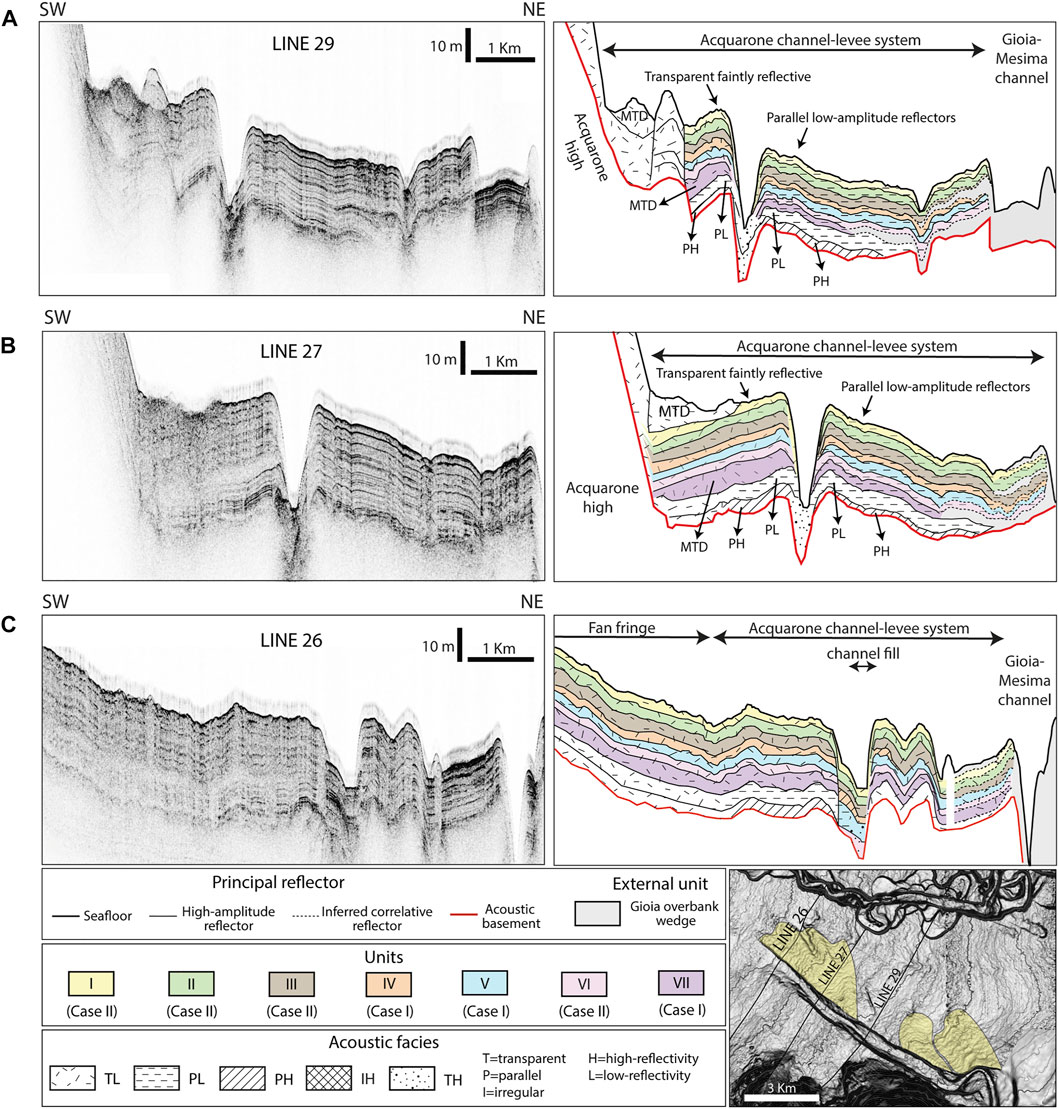
FIGURE 8. To the left the original subbottom Chirp profiles, to the right the subsurface drawing. The different units are marked with colours while the seismic facies with patterns. The acoustic basement is marked by the red line and the Gioia overbank wedge is grey. The seismic profiles are perpendicular to the channel-levee system where both the overbank wedges are well constructed. Line 29 (A) cuts the channel-levee in the partially-confined area (Figure 4A); Line 27 (B) and Line 26 (C) cross the Knick-points area.
The overbank deposits consist of a thick sedimentary wedge that tapers laterally and longitudinally. The left overbank wedge consists of relatively fine-grained sediments (TL) (Figure 8). At the base of the Acquarone high slope, a recent MTD can be recognized thanks to the rough seabed in the channel floor; according to its transparent, faintly reflective facies, it consists of a fine-grained MTD (Figures 8A,B).
In the right levee, the overbank deposits show a less homogeneous character, with varied acoustic facies. In the Bend area (Figure 7A), most of the units (I, II, III, VI and VII) are composed principally of well stratified fine-grained sediments (PL), while Units IV and V have a major coarse-grained component (PH). In the Laterally confined area (Figure 7B), there is a prevalence of well stratified fine-grained deposition (PL). At the end of the confined tract, in the Knick-points area, the left overbank deposits are composed by homogeneous fine-grained sediments (TL), while the right overbank by well-stratified fine-grained sediments (PL) (Figures 8A,B).
The seven seismic units recognized in the overbank wedges extend downslope, in the frontal splay and fan fringe elements. The frontal splay and the fan fringe are composed of different acoustic facies that vary longitudinally and laterally. The first 8 m (Units I, II, and III) of the Frontal splay area consist of relatively homogeneous fine-grained sediments (TL) (Figure 9). This low-amplitude package drapes more reflective deposits interpreted to be composed of relatively coarse-grained sediments (TH) of Units IV and V (Figure 9A). Their high reflectivity strongly attenuates the acoustic signal, making the recognition of the deeper units uncertain, which are thus characterized only on the basis of some minor reflections. In the fan fringe, the downslope continuation of Units IV, V, and VII present irregular high-amplitude reflectors interpreted as laterally discontinuous coarse-grained sediments, laterally the reflectors have a parallel configuration and slightly decrease in amplitude (PL) highlighting better organization and an increase in the fine content (Figure 9C).
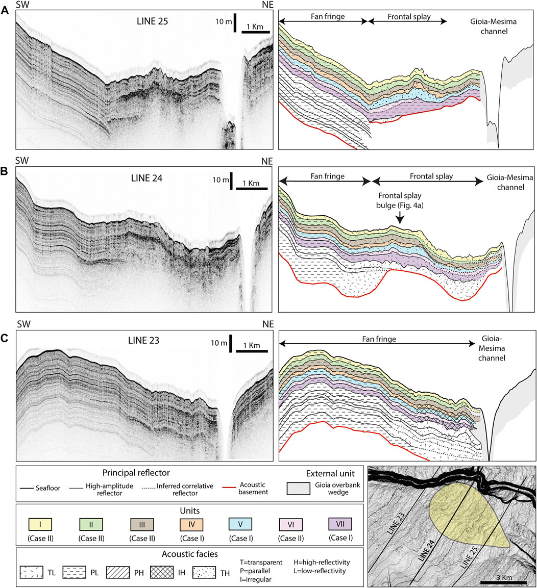
FIGURE 9. To the left the original subbottom Chirp profiles, to the right the subsurface drawing. The different units are marked with colours while the seismic facies with patterns. The acoustic basement is marked by the red line and the Gioia overbank wedge is grey. Line 25 (A) and Line 24 (B) cut the Frontal splay area and the lateral fan fringe. Line 23 (C) is perpendicular to the fan fringe.
The isopach maps of the seven units show the sediment distribution within the entire turbidite system (Figure 10). Each unit is characterized by a distinctive distribution of sediments, thus pointing to highly spatial variability of overspilling flow behaviour over time. In particular, the depocenters location and their seismic response are indicative of two main patterns of deposition in the Acquarone Fan. Each unit displays one of the two depositional patterns, named Case I and Case II.
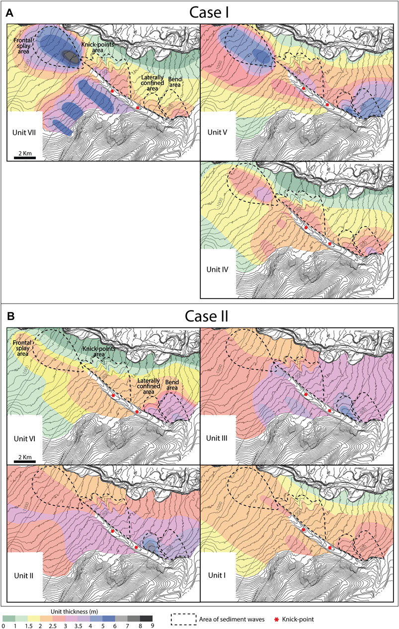
FIGURE 10. Thickness maps of the seven (VII-I) units in the Acquarone Fan. The units have been grouped in Case I (Unit VII, V and IV) and Case II (VI, III, II, and I) since they present two different sediment distribution patterns. (A) Case I units have depocenters in the Bend area, Knick-points area and Frontal splay area (only Unit V has thick accumulation also in the Laterally confined area). (B) Case II units show more homogeneous sediment distribution on the overbank, with the exception of Units II and III that have a depocenter in the Laterally confined area, and slightly thin in the frontal splay.
Case I depositional pattern has three depocenters, in the Bend area, Knick-points area and Frontal splay area. This pattern is displayed by Units IV and VII and by Unit V, which, has a depocenter also in the Laterally confined area (Figure 10A). The depocenter in the Bend area has thicker values near the levee crest, where sediment waves are better developed and are upslope asymmetric (Figure 5B). The depocenter in the Knick-points area starts laterally to the flat sector downslope from KP1. The depocenter in the Frontal splay area has a convex shape, with maximum accumulation along the axis, where the sediment waves develop (Figure 6), and decreasing thickness laterally and downslope. In the Frontal splay area units IV and V are composed of homogeneous/laterally discontinuous coarse-grained sediments.
Case II depositional pattern is displayed by Units I, II, III, and VI (Figure 10B). The second pattern of deposition is characterized by thickness mostly constant on the overbank, with only slightly increasing values in the Bend area, and a slight decrease in the frontal splay. Units II and III also present a depocenter in the Laterally confined area with maximum values near the levee crest (Figure 10B). At the end of the channel, the units are homogeneously distributed on the slope with a slightly thicker accumulation in the fan fringe than in the frontal splay. Case II units, in the Frontal splay area, show a homogeneous fine-grained composition.
Moreover, the thickness maps show that, concomitantly with the deposition of Units I, III, IV, and VII the Acquarone high was affected by multiple landslides, finally deposited on the left overbank. The recurrence of MTD deposits in the same position in different time intervals highlight the reactivation of the landslide headwall resulting in its retrogression (Figure 10).
Generally, in the northern hemisphere, the Coriolis force causes more sediment overspill in the right levees, which, therefore, are often higher than the left ones (Mutti and Normark, 1987; Abd El-Gawad et al., 2012; Wells and Cossu, 2013). On the contrary, in the Acquarone channel-levee system, the left levee is in general higher than the right one (Figure 4B). At the beginning of the partially confined area, this difference in relief is partly due to the structural setting, since the left levee grows on a more elevated terrain than the right levee, as highlighted by the relief of the acoustic basement in Line 29 (Figure 8A). Downslope, however, the acoustic basement reveals that the difference in relief is due to the greater aggradation of the left levee, since both the levees had initially the same height (Figure 8B). The left levee relief started to overcome that of the right one from the deposition of Unit VII. The isopach map shows that Unit VII presents an elongate depocenter on the left overbank running parallel to the levee crest (Figure 10A). It has been interpreted that part of this body is composed by an MTD coming from the retrogressive scarp located on the Acquarone high. Figure 8B shows that the volume of the MTD on the left overbank area, enhanced the left levee to overcome the relief of the right one, inverting the characteristic asymmetry of the channel-levee system of the northern hemisphere.
The most important parameters controlling overbank composition are vertical distribution of different grain-sizes in relation to the height of the levee (Straub and Mohrig, 2008; Hansen et al., 2015; Jobe et al., 2017). In fact, the relief of the levees, depending on the vertical grain-size, will control the partitioning of different grain-sizes between the in-channel flow and deposits on the levee, directly influencing the composition of the overbank wedges (Pirmez et al., 1997; Peakall et al., 2000; Pirmez and Imran, 2003).
Before the MTD deposition, the difference in relief between the right and left levee appears to have been negligible as they show the same seismic response on each side (Figures 8A,B). In this case, the same grain-sizes reached the right and left levee crest (Figure 11). However, after the deposition of the MTD, the two overbank wedges of the Acquarone fan show markedly different seismic responses. The right overbank is principally characterized by parallel low-amplitude reflector indicative of a relatively well stratified fine-grained sediment, whereas, in the left overbank wedge, the absence of any internal structure and faintly reflective seismic facies could be indicative of homogeneous and structureless fine-grained deposition (Figures 8A,B).
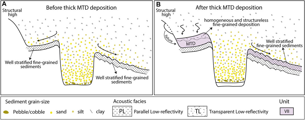
FIGURE 11. Schematic diagram of the channel-levee illustrating how the interplay between the levee relief and the vertical distribution of the grain-sizes can affect the deposition on the overbank. (A) Before the MTD deposition the same grain-sizes reached the levees producing analogous deposits on the opposite overbanks, (B) while after the MTD deposition, the increased difference in levee relief led to a different segregation of the flow producing lithologically different deposits on the opposite overbanks.
Our case study shows that, the geologically-instantaneous emplacement occurrence of an MTD on the left overbank asymmetrically increased the levee relief and so the confinement of the flow towards the side interested by the failure. The stratification of the flow combined with the increase in confinement, led to the preferential overspill of coarser grain-seizes on the less elevated overbank, producing stratified deposits with sand beds (Figure 11). Instead, only fine grain-sizes, are able to reach the surface of the higher levee, creating homogenous mud-dominated deposits (Figure 11). This process led to drastic change in the resulting overbank composition that can have important consequences on facies prediction: the proximity with a structural high can originate overbank deposit with higher sand % respect to the opposite wedge where finer deposition can occur and interrupt the lateral continuity of sand beds.
We conclude that the occurrence of collapses from the Acquarone high and landslide deposition on the left levee caused significant differences in the levee topography and, consequently, in the composition of the overbank wedges. Therefore, the Acquarone fan sheds light on a mechanism, i.e. slope failure, whereby channel-levee systems in topographically complex areas deviate from the characteristic asymmetry connected to the action of the Coriolis force.
The two pattern of sediment distribution (Case I and II) and their seismic response, suggest that two types of flows, with distinct dynamics, are responsible for the different distributions of the seven depositional units in the study area. Of the many parameters that characterize turbidity currents, flow density is fundamental in controlling their depositional pattern (Lowe, 1982). We have thus explored the possibility that flows with an initial different density and internal structure may interact differently with the seafloor topography, exploiting distinct overbank points along the channel and following different flow paths in the overbank and frontal splay areas. We follow the definition of the flow type in the classification by Lowe (1982), which distinguishes high and low-density turbidity current depending on their dominant grain-size population.
Low density turbidity currents consist largely of clay, silt and fine-to about medium-grained sand-size particles that can be maintained in the flow by turbulence alone. Conversely, high-density turbidity currents can include particles coarser than about medium-grained sand, which are supported by different mechanisms dependent on concentration effects. We have also taken into account that, in many cases, turbidite flows are bipartite, with a coarser-grained basal part behaving as high-density turbidity current and a finer-grained top behaving like a low-density one (Lowe, 1982; Mutti et al., 2003; Tinterri et al., 2003).
As summarized in Figure 12, in the study area, in Case I (Figure 12A) the bulk of sediments are deposited in the frontal splay with a transparent high-reflectivity acoustic facies indicative of prevalently coarse-grained sediment and producing a positive topography, which we interpret as resulting from high-density turbidity currents. On the contrary, in Case II (Figure 12B) a transparent low-reflectivity acoustic facies prevail and indicate a mud prone frontal splay, associated very likely with low-density turbidity currents even if the presence of mud-rich hybrid beds (sensu Haughton et al., 2009) cannot be completely ruled out.
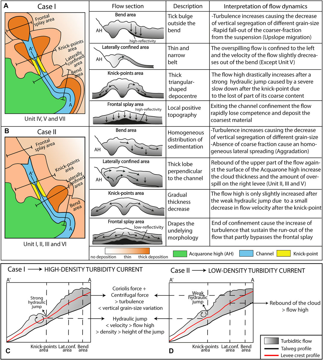
FIGURE 12. Summary sketch of the two patterns of overbank sediment distribution, Cases I (A) and II (B) and schematic cross-sections of the flow highlighting the relevant flow dynamics. Below, the longitudinal variation in flow thickness, for Cases I (C) and II (D) and inferred variations in flow proprieties connected to the dynamics of the hydraulic jumps around the knick-points.
The reason for privileging the interpretation linked to low density turbidity currents lies in the fact that, theoretically, the difference in acoustic impedance between the lithological internal divisions of hybrid beds should produce a reflection in the seismic profile whereas the frontal splay of the study area is characterized by transparent acoustic facies. Furthermore, the increase of the slope gradient downcurrent to the channel mouth (Figure 4A) would enhance the bypass of hybrid flows away from the frontal splay area rather than their deposition. Indeed, hybrid beds, deposited by transitional flows where the cohesive forces prevail over turbulence, tend to be more common into lateral and distal lobe fringes and basin plains and, more in general, where reduction in seafloor gradient favors flow deceleration and deposition (Haughton et al., 2009; Tinterri and Muzzi Magalhaes, 2011; Talling, 2013; Kane et al., 2016).
Our reconstruction show that the two types of flow behaviour characterize specific time intervals and alternate during the construction of the overbank wedge through the deposition from unit VII to I.
Bends are crucial morphological elements that affect sediment distribution in the channel and overbank areas. In this case study, the origin of the bend is connected to the presence of the Acquarone high that deviates the channel pathway from a N-S to a NW-SE direction. The lateral confinement imposed by the Acquarone high led to a large amount of sediment discharge outside the bend on the eastern right levee (Figure 10).
The backslopes of channel levees are in general thought as sites of fine-grained turbidity currents and of predominantly mud and silt deposition (Mutti and Normark, 1987; Normark et al., 2002; Wynn and Stow, 2002; Hansen et al., 2015). In a current able to transport various grain sizes, the coarse sediment fraction is concentrated near the base of the current, while finer sediment fractions are more homogenously distributed over the height of the current (Kneller and Buckee, 2000) (Figure 13). Progressive levee construction increases flow confinement and, accordingly, causes reduction in the grain-size of the sediment that can overspill the channel. As a consequence, an overall fining-upward trend generally characterizes the overbank sequence (Hansen et al., 2015).
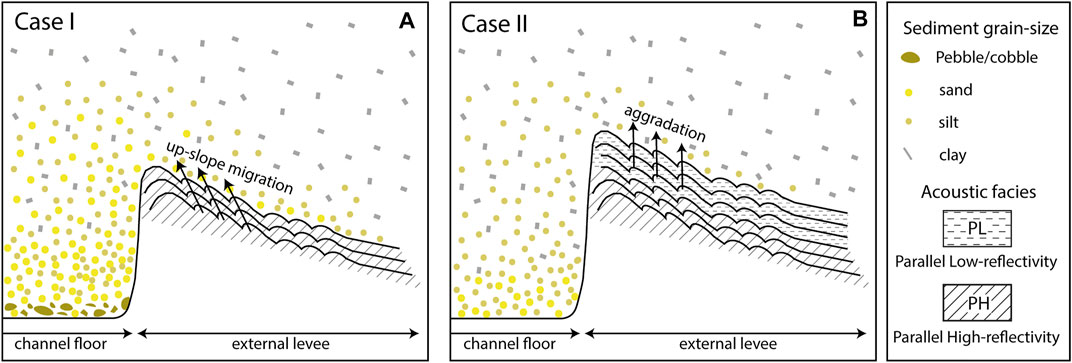
FIGURE 13. Schematic diagram of the channel belt and the external levee showing the interaction of (A) High-density turbidity current (Case I) and (B) Low-density turbidity current (Case II) with topography and the different migration direction of the sediment waves created by the two types of flow on the outer levee slope.
On the outer side of the bend of the Acquarone channel, despite the high relief of the levee crest (about 60 m), Units IV and V (Case I) are characterized by a high-reflectivity interpreted as deposits with a percentage of coarse-grained sediments (Figure 7A). There is a drastic change of facies between Unit IV and the overlying units belonging to Case II consisting in 8.5 m of relatively fine-grained deposit, as inferred from the low acoustic reflectivity (Figure 7A). The passage between PH and PL facies is sharp and abrupt, indicating that a sudden change in the proprieties of the flows occurred after the deposition of Unit IV. According to Baas et al. (2005), highly-turbulent flows keep the coarser particles more easily in suspension, owing to an upward directed component of turbulent velocity that overcomes the falling velocity of most particle sizes. This effect would eventually cause a decrease in the vertical segregation of the different grain-sizes compared to flows with weaker turbulence. In the study area, the high gradient of the confined tract (1.15°, Figure 4B) and the centrifugal force at the bend are consistent with an increase in the flow velocity, which can develop high turbulence. So, we suggest that, in Case I, whose parent flows have a high percentage of sand fraction, the increased turbulence enhanced the coarser fraction to reach the upper part of the flows and overspill. Therefore, the overbank deposit created by high-density turbidity currents has a higher sand to mud ratio than the product of low-density turbidity currents, which does not account for a significant coarse-grained fraction to be transported over the levee crest (Figure 13B).
Sediment waves in the Bend area, in their early phase (Case I), are associated with parallel reflector with a high-reflectivity and have slow rates of up-current migration (Figure 5C, 13A). Anyway, later (Case II), the migration rate diminishes, the seismic response becomes less reflective and pure aggradational growth prevails (Figure 5C, 13B). Generally, up-current migrating sediment waves are associated with thicker and more abundant sand beds on their stoss side (Normark et al., 2002; Kostic, 2014). This general observation is consistent with a higher sand content in the overflow connected to Case I, further substantiating that they can be associated with high-density turbidity currents.
Generally, in a leveed-channel system, the upper part of turbidity currents continuously over-spills onto the overbank area and the flows within the channel are progressively depleted of fine-grained material (Peakall et al., 2000; Hansen et al., 2015). As a consequence, the thickness of overbank units is expected to decrease in a downstream direction. On the contrary, in the Laterally confined area of the right levee, Units II, III (Case II), and V (Case I) have higher thickness than upslope (Figure 10). This unusual and localized increase in sedimentation can have two different explanations:
1) A localized reduction in the channel depth value enhances the overspill of a thicker part of the flow. Different depositional features may reduce the channel relief, such as nested mounds that develop on the outside of a specific bend (i.e. the first sharp bend) (Peakall et al., 2000) or MTD coming from the surface of the Acquarone high. However, those feature cannot be recognized, as, if present, they are now buried under the more recent MTD (Figure 2).
2) The flow experienced a reflection on the surface of the structural high.
In the case of the first hypothesis, the overspill of the lower, coarser-grained part of the flows should result in a high-amplitude seismic facies, similar to what observed in the high-density flows of Case II. This is not the case, as shown by Figure 7B, which highlights the low-amplitude parallel reflections of the overbank wedge. Therefore, we prefer the second hypothesis also because it is consistent with the spreading direction of the lobe-shaped depocenter in the Laterally confined area that is almost specular to the channel path at the bend. It can be hypothesized that the confining action of the Acquarone high could impose the thickening and the successive rebound of the upper portion of the flow outgoing from the bend (Figures 12B,D). In fact, a turbidity current can be reflected depending on the geometry of the bounding slope and the angle of incidence of the current (Patacci et al., 2015). This assemblage has commonly been detected in tectonically confined basins (Kneller et al., 1991; Kneller and McCaffrey, 1999; Amy et al., 2004; Tinterri et al., 2016, 2017; Tinterri and Piazza, 2019) resulting in the production of contained-reflected beds (sensu Pickering and Hiscott, 1985). Dalla Valle and Gamberi (2009) and Tek et al. (2021) provide other examples where changes of the overbank architecture are interpreted to be connected to flow reflection processes.
Laboratory experiments (Kneller et al., 1991; Kneller 1995; Haughton 1994; Amy et al., 2005; Patacci et al., 2015) and numerical models (Howlett et al., 2019) have shown that a reverse overflow forms as soon as a turbidity current impacts on a topographic high and a deceleration from supercritical to subcritical condition is accompanied by abrupt flow inflation. However, in order to produce a reflected overflow, the upper part of the flow should have sufficiently high momentum, so when the outbound velocity is too low at the point of incidence with the slope, turbidity-current reflection is not achieved (Patacci et al., 2015). In the case of the Acquarone channel, it is reasonable to argue that turbidity currents that spilled over the left side of the channel experienced complete reflection, being impeded in their travel by the Acquarone High (Figure 12B). However, the sedimentation patterns of Units I, IV, VI, and VII do not show this depocenter (Figure 12A). Probably the turbidity currents that generated those units had insufficient velocity due to their strongly depositional behaviour at the bend. In fact, as the current enters the bend and spills over onto the overbank, the in-channel velocity decreases significantly (Abd El-Gawad et al., 2012). Other flow proprieties, such as the volume of the low-density part of the flow and the height of the overspilling flow, could be involved in the occurrence of a reflected overflow, but they cannot be evaluated with the data presently available.
The relief of levees above the channel floor commonly diminishes in a downslope direction (Hiscott et al., 1997; Posameinter and Kolla, 2003; Hansen et al., 2015). In our case study, along the flat segments (flat I-II, Figure 4C) downslope from knick-points, the relief of the levees crest increase (respectively about 7 and 3 m for the right levee and 5 and 4 m for the left one) vs. the upslope levee tract (Figure 4C). This increase in relief could be due to a localized increase in the erosional behaviour of turbiditic flows in the channel floor or to an increase in the growth rate of levee crests. The latter hypothesis is here preferred because the flat I segment on the levee crest profiles coincides with the upslope apex of a depositional field of bedforms (Figure 12A).
In the Knick-points area, the units that fall into Case I show a marked depocenter highlighting increased capability of flows to overtop the levee crest (Figure 12A). A reduction in flow velocity is to be expected when a flow passes through a knick-point (Heijnen et al., 2020). Considering the inverse relationship between flow velocity (U) and flow height (h) marked by the Froude number
where ρ = density of the flow, ρw = density of water and g = acceleration of gravity, flow thickening is connected to flow deceleration.
In the Acquarone channel, slopes are always one order of magnitude above the 0.1° threshold gradient for Froude supercritical flow deposits (Postma et al., 2014). This is why it is reasonable to assume that, irrespective of their nature, all the turbidity currents reached the supercritical conditions and, passing the knick-point, experienced a hydraulic jump. We suggest that in the flat I segment (Figure 4C), where the slope of the channel axis is halved, the turbidity currents rapidly slow down and go through a hydraulic jump, whose consequence is the thickening of the flow and the entrainment of water that reduce the density of the current (Figure 14) (Komar, 1971; Postma et al., 2009).
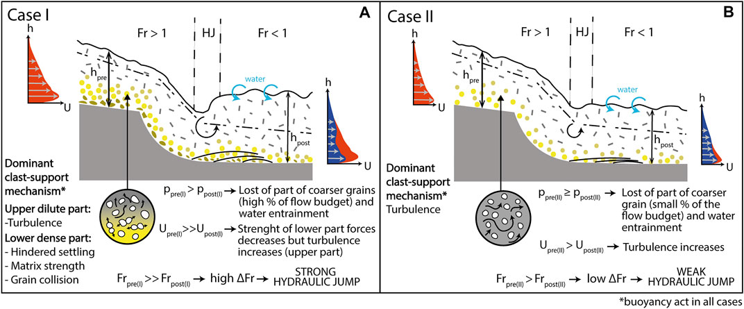
FIGURE 14. Schematic diagram of the interpreted flow high transformation of supercritical turbidity currents through a hydraulic jump in the knick-point. (A) Supercritical high-density turbidity current (Case I) is expected to experience strong deceleration after the hydraulic jump because of the loss of part of its coarse-grained particles, which, through clast interactions, creates the principal clast-support mechanism in the lower part of the flow. (B) Supercritical low-density turbidity current (Case II) goes through a milder velocity reduction after the hydraulic jump because its principal clast-support mechanism is maintained and further alimented after the jump.
Recent experiments by Ono et al. (2021) were carried out on a mixture of sediment (including fine-sand to gravel), simulating flows equivalent to the high-density turbidity currents according to the definition of Lowe (1982). The results of Ono el al. (2021) show that after the occurrence of a large hydraulic jump, where the flow depth increased eight time respect the initial value, smaller ones, where the flow was only two times thicker than the initial value, occurs. We have interpreted that the flow behaviour of Case I in the KP1 could thus be connected to a drastic increase in flow thickness. This process can account for a long-lasting overspill and for the formation of the depocenter associated with the Knick-points area (Figure 12A). Anyway, only Unit VII show a depocenter occurring after the KP2. Accordingly with the data of Ono et al. (2021), we interpreted the absence of a depocenter after KP2 for Unit V and IV to be connected to a possibly smaller hydraulic jump whose effect are potentially not related to a long-lasting overspill. The smaller size of the jump can be connected to a slow-down of the velocity of the flow following the first hydraulic jump and to the milder slope difference between the second ramp (1, 2°) and the second flat (0, 9°) that could have not provided sufficient deceleration to the flow.
Similarly, Case II, interpreted as associated to low-density turbidity currents, does not show any increase in sedimentation in the Knick-points area (Figure 12B). This occurrence is here explained as also resulting from a smaller hydraulic jump. In the crossing of a topographic step, the height of the jump has been described as the ratio of Froude number before (Frpre in Figure 14) and after the jump (Frpost in Figure 14). The higher the difference between the Froude number values (∆Fr in Figure 14), before and after the jump, the higher the size of the hydraulic jump (Cartigny et al., 2014).
The lower part of bipartite turbidity currents consist of a relatively dense basal layer sustained by the combined effect of hindered settling, matrix strength and dispersive pressure controlled by sediment concentration (that may exceed 20–30% according to Lowe, 1982). In contrast, a dilute, turbulent low-density turbidity current is primarily sustained by turbulence which is largely independent from particle concentration (Lowe, 1982). The flow deceleration related to the hydraulic jump, in high-density turbidity currents, causes the en-masse deposition of the coarsest particles of the basal layer (Postma and Cartigny, 2014; Postma et al., 2014; Hage et al., 2018; Slootman and Cartigny, 2020) and the concentration of the basal dense layer is further reduced by the water entrainment effect (Figure 14A). As a consequence, we can expect that high-density turbidity currents experience a drastic slowdown after KP1, due to the marked decrease in sediment concentration, producing a strong hydraulic jump with the consequent increase in sediment deposition on the levee (Figure 14A). While low-density turbidity currents, whose principal transport mechanism is the turbulence of the fine-grained sediments, are expected to experience a milder velocity reduction after KP1 producing a weak hydraulic jump (Figure 14B).
In summary, we suggest that the pattern of sediment distribution created by Case I in the Knick-points area, consisting in a localized increase in the overbank thickness, is the result of high-density turbidity currents experiencing a strong hydraulic jump (Figure 12C); while the sedimentation pattern of Case II does not generate a depocenter in the same area since their former flows (low-density turbidity currents) are interpreted as producing smaller and weaker hydraulic jumps (Figure 12D). We have interpreted the knick-points, inferred by tectonic structures transverse to the channel course whose topography is not completely healed, led to the occurrence of hydraulic jumps whose amplitude, that can be connected to the density stratification of the flow, may or not have a depositional expression on the overbank area.
The thickness distribution of the seven units shows that the two different types of flow behave differently also under the rapid flow expansion regime ensuing at the end of the channel confinement. Units falling in Case I present a thick and elongate lobe with very high reflectivity (Figure 12A). This kind of deposition is interpreted as resulting from high-density turbidity currents that, exiting the channel confinement, rapidly lose competence, deposit the coarsest material and create a thick frontal lobe with small-scale coarse grained sediment waves in front of the channel mouth (Figure 6). Moreover, the direction of the crests is indicative of another important behaviour of the lower dense portion of the turbidity current. Where the relief of the bulge in the frontal splay becomes important (Figures 4A, 9B), the sediment wave crests divert by about 30° eastward from their initial WWN-EES orientation (Figure 6). Similar results can also be observed in field studies and flume experiments related to flow deflection against lateral or oblique confining slopes (Amy et al., 2004; Tinterri et al., 2017; Piazza and Tinterri, 2020). The mud portion is completely absent, as shown by the transparent high reflectivity of the frontal splay (Figure 9A), indicating that the upper dilute part of the turbidity currents largely bypassed this area or were eroded by successive flows.
Units belonging to Case II do not present any thick concave upward accumulation, but, rather, deposition on the frontal splay results in a low-reflectivity package, which drapes the underlying morphology (Figure 12B). Sedimentation is higher towards the SW, in the fan fringe, than adjacent to the channel mouth where much of the sediment bypasses and is carried further downslope in the Gioia channel. The loss of confinement at the end of the channel is generally associated with an increase of turbulence in turbidity currents. The increase in turbulence at the mouth of submarine channels has been connected both to the occurrence of hydraulic jump (Mutti and Normark, 1987; Mutti and Normark, 1991; Mutti et al., 2003; Baas et al., 2004) and to flow relaxation mechanism (Pohl et al., 2019). In turbidity currents with a substantial mud component, as low-density turbidity currents, increase in turbulence, which, preventing sediment deposition, contributes to the flow run-out (Mutti and Normark, 1987; Mutti and Normark, 1991; Mutti et al., 2003). Moreover, the high value of the slope (1.2°, Figure 4B) and the convergence created by the topography in the frontal splay caused turbidity currents to accelerate in the principal flow direction, while laterally, in the fan fringe, the gentler slope caused a little bypass and a greater amount of fine-grained deposition. In fact, low-density turbidity currents react to the end of confinement and to the morphology of the slope in the same way as the upper dilute part of high-density turbidity currents.
A detailed analysis of sediment thickness and facies has been performed to investigate overbank processes in a leveed channel in a slope setting located in the southeastern Tyrrhenian Sea. It reveals considerable complexity in levee facies and thickness, ultimately ensuing from the uneven seafloor topography of the study area, highlighting that, in continental slope settings, where the imprint of tectonic structures is not yet completely healed, sedimentation in overbank areas does not conform to the available, simple predictive models.
In particular, we show that structural highs can confine overbanking turbidity currents, inducing flow deflection, and forming localized depocenters in the levees. Such an interaction between overbanking flows and confining structural highs can eventually lead to reverse channel asymmetry, opposite to what would result from the effect of the Coriolis force alone.
In addition, our research also highlights that planform and gradient variations of slope channels can have a strong influence on the thickness trend in the overbank areas. In particular, we show that overbank depositional patterns change along the channel course depending on the location of bends and knickpoints. This behaviour is recognized in the majority of submarine channels and interpreted as resulting from local perturbations in channel planform and gradient depending on autogenic processes inherent with channel development. Our case study, on the contrary, shows that bends and knick-points can have a tight connection to slope topography, thus further conjoining overbank depositional patterns and allogenic, tectonic shaping of a continental margin.
We have also shown that sediment wave fields coincide with depocenters on the overbank region, indicating that they develop from the principal sediment entry-points. According to their location, the sediment waves have different dimensions and geometries highlighting that the interaction between the overspilling flows and slope topography, influences not only sediment distribution, but also the morphology of the sediment waves. Moreover, our study shows that the direction of migration of sediment waves is connected to the density of the turbidity current: high-density turbidity currents create upslope-migrating coarse-grained sediment waves, whereas low-density turbidity currents are associated with aggrading fine-grained sediment waves.
Finally, our study also shows that patterns of overbank deposition vary over time. We envisage that, upon interacting with gradient variations along the channel course, turbidity currents behave differently, depending on their vertical density profiles. In particular, hydraulic jumps formed by high- and low-density turbidity currents control the amount of sediment that can overspill the channel and the character and location of overbank depocenters. This finding highlights the importance of antecedent conditioning by previous flows in controlling the development of turbidite systems Migeon et al., 2000.
The original contributions presented in the study are included in the article/Supplementary Material, further inquiries can be directed to the corresponding author.
SE and GF are responsible for the conception of the study. SE performed the description and manipulation of the data, wrote the first draft of the manuscript and created the images. SE and GF are involved in the main interpretations of the paper. GF wrote the conclusion section of the manuscript. GF and TR contributed to the design of the paper and corrected the paper. All authors contributed to manuscript read and approved the submitted version.
The authors declare that the research was conducted in the absence of any commercial or financial relationships that could be construed as a potential conflict of interest.
All claims expressed in this article are solely those of the authors and do not necessarily represent those of their affiliated organizations, or those of the publisher, the editors and the reviewers. Any product that may be evaluated in this article, or claim that may be made by its manufacturer, is not guaranteed or endorsed by the publisher.
We would like to thank all the participants (ISMAR colleagues, captain and crew) of the various cruises of data acquisition. We are also grateful to Alessandra Mercorella for the processing and management of the data. Finally, we particularly thank the editor Michael Clare and two reviewers for their thorough reviews that have improved the quality of the manuscript.
Abd El-Gawad, S., Cantelli, A., Pirmez, C., Minisini, D., Sylvester, Z., and Imran, J. (2012). Three-dimensional Numerical Simulation of Turbidity Currents in a Submarine Channel on the Seafloor of the Niger Delta Slope. J. Geophys. Res. 117, a–n. doi:10.1029/2011JC007538
Adeogba, A. A., McHargue, T. R., and Graham, S. A. (2005). Transient Fan Architecture and Depositional Controls from Near-Surface 3-D Seismic Data, Niger delta continental Slope. Bulletin 89 (5), 627–643. doi:10.1306/11200404025
Amy, L. A., McCaffrey, W. D., and Kneller, B. C. (2004). The Influence of a Lateral basin-slope on the Depositional Patterns of Natural and Experimental Turbidity Currents. Geol. Soc. Lond. Spec. Publications 221, 311–330. doi:10.1144/GSL.SP.2004.221.01.17
Antonioli, F., Ferranti, L., Lambeck, K., Kershaw, S., Verrubbi, V., and Dai Pra, G. (2006). Late Pleistocene to Holocene Record of Changing Uplift Rates in Southern Calabria and Northeastern Sicily (Southern Italy, Central Mediterranean Sea). Tectonophysics 422, 23–40. doi:10.1016/j.tecto.2006.05.003
Baas, J. H., McCaffrey, W. D., Haughton, P. D. W., and Choux, C. (2005). Coupling between Suspended Sediment Distribution and Turbulence Structure in a Laboratory Turbidity Current. J. Geophys. Res. 110, C11015. doi:10.1029/2004JC002668
Baas, J. H., van Kesteren, W., and Postma, G. (2004). Deposits of Depletive High-Density Turbidity Currents: a Flume Analogue of Bed Geometry, Structure and Texture. Sedimentology 51, 1053–1088. doi:10.1111/j.1365-3091.2004.00660.x
Birman, V. K., Meiburg, E., and Kneller, B. (2009). The Shape of Submarine Levees: Exponential or Power Law? J. Fluid Mech. 619, 367–376. doi:10.1017/S0022112008004862
Cartigny, M. J. B., Ventra, D., Postma, G., and Van Den Berg, J. H. (2014). Morphodynamics and Sedimentary Structures of Bedforms under Supercritical-Flow Conditions: New Insights from Flume Experiments. Sedimentology 61, 712–748. doi:10.1111/sed.12076
Casalbore, D., Bosman, A., Casas, D., Chiocci, F., Martorelli, E., and Ridente, D. (2019). Morphological Variability of Submarine Mass Movements in the Tectonically-Controlled Calabro-Tyrrhenian Continental Margin (Southern Italy). Geosciences 9, 43. doi:10.3390/geosciences9010043
Casas, D., Chiocci, F., Casalbore, D., Ercilla, G., and de Urbina, J. O. (2016). Magnitude-frequency Distribution of Submarine Landslides in the Gioia Basin (Southern Tyrrhenian Sea). Geo-Mar. Lett. 36, 405–414. doi:10.1007/s00367-016-0458-2
Catalano, S., and Di Stefano, A. (1997). Sollevamenti e tettogenesi pleistocenica lungo il margine tirrenico dei Monti Peloritani: integrazione dei dati geomorfologici, strutturali e biostratigrafici. Il Quaternario 10 (2), 337–342.
Dalla Valle, G., and Gamberi, F. (2010). Erosional Sculpting of the Caprera Confined Deep-Sea Fan as a Result of Distal basin-spilling Processes (Eastern Sardinian Margin, Tyrrhenian Sea). Mar. Geology 268, 55–66. doi:10.1016/j.margeo.2009.10.012
Deptuck, M. E., Sylvester, Z., Pirmez, C., and O’Byrne, C. (2007). Migration-aggradation History and 3-D Seismic Geomorphology of Submarine Channels in the Pleistocene Benin-major Canyon, Western Niger Delta Slope. Mar. Pet. Geology 24, 406–433. doi:10.1016/j.marpetgeo.2007.01.005
Fabbri, A., Ghisetti, F., and Vezzani, L. (1980). The Peloritani-Calabria Range and the Gioia basin in the Calabrian Arc (Southern Italy): Relationships between Land and marine Data. Geologica Rom. 19, 131–150.
Gamberi, F., Della Valle, G., Marani, M., Mercorella, A., Distefano, S., and Di Stefano (), A. (2019). Tectonic Controls on Sedimentary System along the continental Slope of the central and southeastern Tyrrhenian Sea. Ital. J. Geosciences 138, 317–332. doi:10.3301/IJG.2019.08
Gamberi, F., and Marani, M. (2008). Controls on Holocene Deep-Water Sedimentation in the Northern Gioia Basin, Tyrrhenian Sea. Sedimentology 55, 1889–1903. doi:10.1111/j.1365-3091.2008.00971.x
Gamberi, F., and Marani, M. (2006). Hinterland Geology and continental Margin Growth: the Case of the Gioia Basin (southeastern Tyrrhenian Sea). Geol. Soc. Lond. Spec. Publications 262, 349–363. doi:10.1144/GSL.SP.2006.262.01.21
Gamberi, F., and Rovere, M. (2011). Architecture of a Modern Transient Slope Fan (Villafranca Fan, Gioia basin-Southeastern Tyrrhenian Sea). Sediment. Geology 236, 211–225. doi:10.1016/j.sedgeo.2011.01.007
Hage, S., Cartigny, M. J. B., Clare, M. A., Sumner, E. J., Vendettuoli, D., Hughes Clarke, J. E., et al. (2018). How to Recognize Crescentic Bedforms Formed by Supercritical Turbidity Currents in the Geologic Record: Insights from Active Submarine Channels. Geology 46, 563–566. doi:10.1130/G40095.1
Hansen, L. A. S., Callow, R. H. T., Kane, I. A., Gamberi, F., Rovere, M., Cronin, B. T., et al. (2015). Genesis and Character of Thin-Bedded Turbidites Associated with Submarine Channels. Mar. Pet. Geology 67, 852–879. doi:10.1016/j.marpetgeo.2015.06.007
Haughton, P., Davis, C., McCaffrey, W., and Barker, S. (2009). Hybrid Sediment Gravity Flow Deposits - Classification, Origin and Significance. Mar. Pet. Geology 26, 1900–1918. doi:10.1016/j.marpetgeo.2009.02.012
Haughton, P. D. W. (1994). Deposits of Deflected and Ponded Turbidity Currents, Sorbas Basin, Southeast Spain. J. Sediment. Res. 64, 233–246. doi:10.1306/D4267D6B-2B26-11D7-8648000102C1865D
Heijnen, M. S., Clare, M. A., Cartigny, M. J. B., Talling, P. J., Hage, S., Lintern, D. G., et al. (2020). Rapidly-migrating and Internally-Generated Knickpoints Can Control Submarine Channel Evolution. Nat. Commun. 11, 3129. doi:10.1038/s41467-020-16861-x
Heiniö, P., and Davies, R. J. (2007). Knickpoint Migration in Submarine Channels in Response to Fold Growth, Western Niger Delta. Mar. Pet. Geology 24, 434–449. doi:10.1016/j.marpetgeo.2006.09.002
Hiscott, R. N., Hall, F. R., and Pirmez, C. (1997). Turbidity-current Overspill from the Amazon Channel: Texture of the silt/sand Load, Paleoflow from Anisotropy of Magnetic Susceptibility, and Implications for Flow Processes. Proc. Ocean Drilling Program Scientific Results 155, 53–78. doi:10.2973/odp.proc.sr.155.202.1997
Howlett, D. M., Ge, Z., Nemec, W., Gawthorpe, R. L., Rotevatn, A., and Jackson, C. A. L. (2019). Response of Unconfined Turbidity Current to Deep‐water Fold and Thrust belt Topography: Orthogonal Incidence on Solitary and Segmented Folds. Sedimentology 66, 2425–2454. doi:10.1111/sed.12602
Jobe, Z., Sylvester, Z., Bolla Pittaluga, M., Frascati, A., Pirmez, C., Minisini, D., et al. (2017). Facies Architecture of Submarine Channel Deposits on the Western Niger Delta Slope: Implications for Grain‐size and Density Stratification in Turbidity Currents. J. Geophys. Res. Earth Surf. 122, 473–491. doi:10.1002/2016JF003903
Kane, I. A., McCaffrey, W. D., Peakall, J., and Kneller, B. C. (2010). Submarine Channel Levee Shape and Sediment Waves from Physical Experiments. Sediment. Geology 223, 75–85. doi:10.1016/j.sedgeo.2009.11.001
Kane, I. A., Pontén, A. S. M., Vangdal, B., Eggenhuisen, J. T., Hodgson, D. M., and Spychala, Y. T. (2017). The Stratigraphic Record and Processes of Turbidity Current Transformation across Deep-marine Lobes. Sedimentology 64, 1236–1273. doi:10.1111/sed.12346
Kneller, B. (1995). Beyond the Turbidite Paradigm: Physical Models for Deposition of Turbidites and Their Implications for Reservoir Prediction. Geol. Soc. Lond. Spec. Publications 94, 31–49. doi:10.1144/GSL.SP.1995.094.01.04
Kneller, B., and Buckee, C. (2000). The Structure and Fluid Mechanics of Turbidity Currents: a Review of Some Recent Studies and Their Geological Implications. Sedimentology 47, 62–94. doi:10.1046/j.1365-3091.2000.047s1062.x
Kneller, B., Edwards, D., McCaffrey, W., and Moore, R. (1991). Oblique Reflection of Turbidity Currents. Geol. 19, 250–252. doi:10.1130/0091-7613(1991)019<0250:orotc>2.3.co;2
Kneller, B., and McCaffrey, W. (1999). Depositional Effects of Flow Nonuniformity and Stratification within Turbidity Currents Approaching a Bounding Slope; Deflection, Reflection, and Facies Variation. J. Sediment. Res. 69, 980–991. doi:10.2110/jsr.69.980
Komar, P. D. (1971). Hydraulic Jumps in Turbidity Currents. Geol. Soc. America Bull. 82, 1477–1488. doi:10.1130/0016-7606(1971)82[1477:hjitc]2.0.co;2
Kostic, S. (2014). Upper Flow Regime Bedforms on Levees and continental Slopes: Turbidity Current Flow Dynamics in Response to fine-grained Sediment Waves. Geosphere 10, 1094–1103. doi:10.1130/GES01015.1
Lowe, D. R. (1982). Sediment Gravity Flows: II Depositional Models with Special Reference to the Deposits of High-Density Turbidity Currents. SEPM J. Sediment. Res. 52, 279–297. doi:10.1306/212F7F31-2B24-11D7-8648000102C1865D
Migeon, S., Savoye, B., and Faugeres, J.-C. (2000). Quaternary Development of Migrating Sediment Waves in the Var Deep-Sea Fan: Distribution, Growth Pattern, and Implication for Levee Evolution. Sediment. Geology 133, 265–293. doi:10.1016/S0037-0738(00)00043-9
Mutti, E., and Normark, W. R. (1991). “An Integrated Approach to the Study of Turbidite Systems,” in Seismic Facies and Sedimentary Processes of Submarine Fans and Turbidite Systems (New York: Springer-Verlag). doi:10.1007/978-1-4684-8276-8_4
Mutti, E., and Normark, W. R. (1987). “Comparing Examples of Modern and Ancient Turbidite Systems: Problems and Concepts,” in Marine Clastic Sedimentology. Editors J. K. Legget, and G. G. Zuffa (Dordrecht: Springer), 1–38. doi:10.1007/978-94-009-3241-8_1
Mutti, E., Tinterri, R., Benevelli, G., Biase, D. d., and Cavanna, G. (2003). Deltaic, Mixed and Turbidite Sedimentation of Ancient Foreland Basins. Mar. Pet. Geology 20, 733–755. doi:10.1016/j.marpetgeo.2003.09.001
Nakajima, T., and Kneller, B. C. (2013). Quantitative Analysis of the Geometry of Submarine External Levées. Sedimentology 60, 877–910. doi:10.1111/j.1365-3091.2012.01366.x
Normark, W. R., Piper, D. J. W., Posamentier, H., Pirmez, C., and Migeon, S. (2002). Variability in Form and Growth of Sediment Waves on Turbidite Channel Levees. Mar. Geology 192, 23–58. doi:10.1016/S0025-3227(02)00548-0
Patacci, M., Haughton, P. D. W., and McCaffrey, W. D. (2015). Flow Behavior of Ponded Turbidity Currents. J. Sediment. Res. 85, 885–902. doi:10.2110/jsr.2015.59
Peakall, J., McCaffrey, W. D., Kneller, B. C., Stelting, C. E., McHargue, T. R., and Schweller, W. J. (2000). A Process Model for the Evolution of Submarine Fan Channels: Implications for Sedimentary Architecture Fine-grained Turbidite Systems. AAPG Memoir 72, 68. Tulsa, OK: SEPM Special Publication, 73–88. doi:10.1306/M72703
Piazza, A., and Tinterri, R. (2020). Cyclic Stacking Pattern, Architecture and Facies of the Turbidite Lobes in the Macigno Sandstones Formation (Chattian-Aquitanian, Northern Apennines, Italy). Mar. Pet. Geology 122, 104704. doi:10.1016/j.marpetgeo.2020.104704
Pickering, K. T., and Hiscott, R. N. (1985). Contained (Reflected) Turbidity Currents from the Middle Ordovician Cloridorme Formation, Quebec, Canada: an Alternative to the Antidune Hypothesis. Sedimentology 32, 373–394. doi:10.1111/j.1365-3091.1985.tb00518.x
Piper, D. J. W., and Normark, W. R. (1983). Turbidite Depositional Patterns and Flow Characteristics, Navy Submarine Fan, California Borderland. Sedimentology 30, 681–694. doi:10.1111/j.1365-3091.1983.tb00702.x
Pirmez, C., Hiscott, R. N., and Kronen, J. K. (1997). Sandy Turbidite Successions at the Base of Channel-Levee Systems of the Amazon Fan Revealed by FMS Logs and Cores: Unraveling the Facies Architecture of Large Submarine Fans. Proc. Ocean Drilling Program Scientific Results 155, 7–33. doi:10.2973/odp.proc.sr.155.201.1997
Pirmez, C., and Imran, J. (2003). Reconstruction of Turbidity Currents in Amazon Channel. Mar. Pet. Geology. 20, 823–849. doi:10.1016/j.marpetgeo.2003.03.005
Pohl, F., Eggenhuisen, J. T., Tilston, M., and Cartigny, M. J. B. (2019). New Flow Relaxation Mechanism Explains Scour fields at the End of Submarine Channels. Nat. Commun. 10, 4425. doi:10.1038/s41467-019-12389-x
Posamentier, H. W., and Kolla, V. (2003). Seismic Geomorphology and Stratigraphy of Depositional Elements in Deep-Water Settings. J. Sediment. Res. 73, 367–388. doi:10.1306/111302730367
Postma, G., and Cartigny, M. J. B. (2014). Supercritical and Subcritical Turbidity Currents and Their Deposits--A Synthesis. Geology 42, 987–990. doi:10.1130/G35957.1
Postma, G., Cartigny, M., and Kleverlaan, K. (2009). Structureless, Coarse-Tail Graded Bouma Ta Formed by Internal Hydraulic Jump of the Turbidity Current. Sediment. Geology 219, 1–6. doi:10.1016/j.sedgeo.2009.05.018
Postma, G., Kleverlaan, K., and Cartigny, M. J. B. (2014). Recognition of Cyclic Steps in sandy and Gravelly Turbidite Sequences, and Consequences for the Bouma Facies Model. Sedimentology 61, 2268–2290. doi:10.1111/sed.12135
Regione Siciliana (2006). “Area Territoriale tra Capo Peloro e il bacino del Torrente Saponara (001),” in Relazione 2006. Piano Stralcio di Bacino per l’Assetto Idrogeologico (Palermo: Regione Siciliana).
Remacha, E., Fernandez, L. P., and Maestro, E. (2005). The Transition between Sheet-like Lobe and Basin-Plain Turbidites in the Hecho Basin (South-Central Pyrenees, Spain). J. Sediment. Res. 75, 798–819. doi:10.2110/jsr.2005.064
Rovere, M., Gamberi, F., Mercorella, A., and Leidi, E. (2014). Geomorphometry of a Submarine Mass-Transport Complex and Relationships with Active Faults in a Rapidly Uplifting Margin (Gioia Basin, NE Sicily Margin). Mar. Geology 356, 31–43. doi:10.1016/j.margeo.2013.06.003
Slootman, A., and Cartigny, M. J. B. (2020). Cyclic Steps: Review and Aggradation-Based Classification. Earth-Science Rev. 201, 102949. doi:10.1016/j.earscirev.2019.102949
Straub, K. M., and Mohrig, D. (2008). Quantifying the Morphology and Growth of Levees in Aggrading Submarine Channels. J. Geophys. Res. 113, 20. doi:10.1029/2007JF000896
Sylvester, Z., and Covault, J. A. (2016). Development of Cutoff-Related Knickpoints during Early Evolution of Submarine Channels. Geology 44, 835–838. doi:10.1130/G38397.1
Symons, W. O., Sumner, E. J., Talling, P. J., Cartigny, M. J. B., and Clare, M. A. (2016). Large-scale Sediment Waves and Scours on the Modern Seafloor and Their Implications for the Prevalence of Supercritical Flows. Mar. Geology 371, 130–148. doi:10.1016/j.margeo.2015.11.009
Talling, P. J. (2013). Hybrid Submarine Flows Comprising Turbidity Current and Cohesive Debris Flow: Deposits, Theoretical and Experimental Analyses, and Generalized Models. Geosphere 9, 460–488. doi:10.1130/GES00793.1
Tek, D. E., McArthur, A. D., Poyatos-Moré, M., Colombera, L., Allen, C., Patacci, M., et al. (2021). Controls on the Architectural Evolution of Deep-Water Channel Overbank Sediment Wave fields: Insights from the Hikurangi Channel, Offshore New Zealand. New Zealand J. Geology Geophys., 1–38. doi:10.1080/00288306.2021.1978509
Tinterri, R., Drago, M., Consonni, A., Davoli, G., and Mutti, E. (2003). Modelling Subaqueous Bipartite Sediment Gravity Flows on the Basis of Outcrop Constraints: First Results. Mar. Pet. Geology 20, 911–933. doi:10.1016/j.marpetgeo.2003.03.003
Tinterri, R., Laporta, M., and Ogata, K. (2017). Asymmetrical Cross-Current Turbidite Facies Tract in a Structurally-Confined Mini-basin (Priabonian-Rupelian, Ranzano Sandstone, Northern Apennines, Italy). Sediment. Geology 352, 63–87. doi:10.1016/j.sedgeo.2016.12.005
Tinterri, R., and Muzzi Magalhaes, P. (2011). Synsedimentary Structural Control on Foredeep Turbidites: An Example from Miocene Marnoso-Arenacea Formation, Northern Apennines, Italy. Mar. Pet. Geology 28, 629–657. doi:10.1016/j.marpetgeo.2010.07.007
Tinterri, R., Muzzi Magalhaes, P., Tagliaferri, A., and Cunha, R. S. (2016). Convolute Laminations and Load Structures in Turbidites as Indicators of Flow Reflections and Decelerations against Bounding Slopes. Examples from the Marnoso-Arenacea Formation (Northern Italy) and Annot Sandstones (South Eastern France). Sediment. Geology 344, 382–407. doi:10.1016/j.sedgeo.2016.01.023
Tinterri, R., and Piazza, A. (2019). Turbidites Facies Response to the Morphological Confinement of a Foredeep (Cervarola Sandstones Formation, Miocene, Northern Apennines, Italy). Sedimentology 66, 636–674. doi:10.1111/sed.12501
Wells, M., and Cossu, R. (2013). The Possible Role of Coriolis Forces in Structuring Large-Scale Sinuous Patterns of Submarine Channel-Levee Systems. Phil. Trans. R. Soc. A. 371, 20120366. doi:10.1098/rsta.2012.0366
Wynn, R. B., and Stow, D. A. V. (2002). Classification and Characterisation of Deep-Water Sediment Waves. Mar. Geology 192, 7–22. doi:10.1016/S0025-3227(02)00547-9
Keywords: overbank deposit, submarine fan, turbidity current, channel planform, slope, knick point, hydraulic jump
Citation: Scacchia E, Tinterri R and Gamberi F (2022) The Influence of Channel Planform and Slope Topography on Turbidity Current Overbank Processes: The Example of the Acquarone Fan (Southeastern Tyrrhenian Sea). Front. Earth Sci. 9:785164. doi: 10.3389/feart.2021.785164
Received: 28 September 2021; Accepted: 13 December 2021;
Published: 10 January 2022.
Edited by:
Michael Andrew Clare, University of Southampton, United KingdomReviewed by:
Meg Baker, Durham University, United KingdomCopyright © 2022 Scacchia, Tinterri and Gamberi. This is an open-access article distributed under the terms of the Creative Commons Attribution License (CC BY). The use, distribution or reproduction in other forums is permitted, provided the original author(s) and the copyright owner(s) are credited and that the original publication in this journal is cited, in accordance with accepted academic practice. No use, distribution or reproduction is permitted which does not comply with these terms.
*Correspondence: Elena Scacchia, ZWxlbmEuc2NhY2NoaWFAdW5pcHIuaXQ=
Disclaimer: All claims expressed in this article are solely those of the authors and do not necessarily represent those of their affiliated organizations, or those of the publisher, the editors and the reviewers. Any product that may be evaluated in this article or claim that may be made by its manufacturer is not guaranteed or endorsed by the publisher.
Research integrity at Frontiers
Learn more about the work of our research integrity team to safeguard the quality of each article we publish.