- 1School of Geological Engineering and Geomatics, Chang’An University, Xi’an, China
- 2Mine Geological Disasters Mechanism and Prevention Key Laboratory, Xi’an, China
- 3China Railway First Survey and Design Institute Group Co., Ltd., Xi’an, China
- 4Shaanxi Railway and Underground Traffic Engineering Key Laboratory (FSDI), Xi’an, China
The seismic response is generally amplified significantly near the fault zone due to the influence of discontinuous interfaces and weak-broken geotechnical structures, which imposes a severe geologic hazard risk on the engineering crossing the fault. The Hanjiang to Weihe River Project (phase II) crosses many high seismic intensity regions and intersects with eight large-scale regional active faults. Seismic fortification of the pipelines across the fault zone is significant for the design and construction of the project. A large-scale vibration table test was adopted to investigate the seismic response and fault influences. The responses of accelerations, dynamic stresses, strains, and water pressures were obtained. The results show that the dynamic responses were amplified significantly by the fault zone and the hanging wall. The influence range of fault on acceleration response is approximately four times the fault width. The acceleration amplification ratio in the fault zone generally exceeds 1.35, even reaching 1.8, and the hanging wall amplification ratio is approximately 1.2. The dynamic soil pressure primarily depends on the acceleration distribution and is apparently influenced by pipeline location and model inhomogeneity. The pipeline is bent slightly along the axial direction, accompanied by expansion and shrinkage in the radial direction. The maximum tensile and compressive strains appear at the lower and upper pipeline boundaries near the middle section, respectively. Massive y-direction cracks developed in the soil, accompanied by slight seismic subsidence. The research findings could provide reasonable parameters for the seismic design and construction of the project.
Introduction
Faults are one of the most important geological settings in the Earth’s crust and are developed extensively in western China. Fault activities generally induce various geological disasters, such as ground dislocations, landslides, collapses, and debris flows, posing a significant threat to people’s lives, properties and engineering constructions (Dhakal, 2021; Peng et al., 2021). Pipelines constitute one of the critical infrastructure elements of modern societies and are used to transport gases and waters over long distances. As a lifeline project built either on the ground surface or buried in the soil, the pipeline cannot avoid crossing a fault belt in most conditions. Studying the assessment, mitigation, and treatment of pipelines across faults is significant for the design and construction of projects.
Significant research has been devoted to understanding the behavior of pipelines subjected to a fault. Scientists and engineers generally focus on the following aspects: 1) investigation of seismic damage of pipelines under strong earthquakes; 2) assessment of pipelines crossing the fault adopting analytical methods, numerical simulations, and physical modeling experiments; and 3) mitigation and prevention of pipelines crossing the fault belt.
The stick-slip action of faults generally triggers strong earthquakes, which can cause large displacements to appear at the ground surface, produce strong ground motions in high seismic intensity regions, and pose severe damage to structures. The damage to pipelines in typical strong earthquakes, such as the 1975 Haicheng (Sun and Hou, 1991), 1976 Tangshan (Sun and Shien, 1983), 2002 Alaska (Hall et al., 2003; Honegger et al., 2004), and 2008 Wenchuan earthquakes (Wang et al., 2012), was investigated, which presented the destruction features of structures and primary influencing factors on destructiveness. In the 1978 Miyagiken-Oki earthquake, approximately 350 cases of damage to water and gas pipelines were investigated near the cut-and-fill boundaries of newly developed residential areas (Liang and Sun, 2000). Experiences from strong earthquakes show that underground structures usually suffer minor damage compared with ground structures during a seismic event (Corigliano et al., 2011), and cut-and-cover tunnels are more vulnerable than circular bored tunnels (Hashash et al., 2001). According to statistical analysis, the peak ground velocity, pipeline type, and size are attributed to the seismic damage of buried pipelines (Toprak and Taskin, 2007). The site conditions are more significant than seismic intensity in contributing to pipeline damage. All the investigations provide detailed damage characteristics, models, and mechanisms for the analysis and design of the pipeline.
The behaviors of lifeline engineering structures crossing faults have been investigated by many researchers adopting the methods of theoretical analysis. Newmark and Hall (Newmark and Hall, 1975) developed a simplified analysis method assuming that a pipeline is subjected to direct stress by the dislocation, ignoring nonuniform lateral soil resistance. On this basis, many researchers extended corresponding works (Kennedy et al., 1979; Duan et al., 2011; Uckan et al., 2015). A refined analysis method for the buried pipeline was presented considering some modification of previous assumptions, which is applicable to both strike-slip and reverse strike-slip faults (Wang and Yeh, 1985). Researchers investigated the buried pipeline responses to strike-slip fault movement, where the large deflection pipeline crossing the fault zone is modeled as an elastica, and the remaining portion of the small deflection pipeline is modeled as a semi-infinite beam on an elastic foundation (Chiou et al., 1994). A simplified method was developed to estimate the curvatures of continuous pipelines due to normal fault movement (Shi et al., 2018). All analytical methods provide the basis for the rapid evaluation of structural deformation and damage across fault zones.
Considerable numerical simulations and large-scale physical model tests were adopted to analyze structures that cross faults under special and complex conditions. The influence of pipeline shell thickness, buried depth, fault zone width, fault displacement, intersection angle of pipeline and fault, material nonlinear characteristic, etc., were taken into account systematically during the numerical simulations (Joshi et al., 2011; Karamitros et al., 2011; Chen et al., 2012; Yang et al., 2013; Vazouras and Karamanos, 2017; Demirci et al., 2018; Dezhkam and Nouri, 2018; Sarvanis et al., 2018; Yifei et al., 2018; Fard et al., 2019; Fadaee et al., 2020). Centrifuge model tests were implemented for segmental tunnels subjected to a normal fault and for a high-density polyethylene pipeline crossing a strike-slip fault (Abdoun et al., 2009; Kiani et al., 2016). A few shaking table tests on deep-buried pipelines (Yan et al., 2018), mountain tunnel flexible joints (Shen et al., 2020), and shield tunnel multiscale physical models (Bao et al., 2017) that passed through a fault zone were also implemented. The vulnerability assessment of natural gas pipelines subjected to seismic actions was explored (Tsinidis et al., 2019; Tsinidis et al., 2020a; Tsinidis et al., 2020b). All of these results provided parameters, methods, and schemes for the design and construction of engineering structures across a fault zone and paved the way for subsequent scientific research.
Engineers are usually very concerned about reducing the possibility of damage to the facilities triggered by faulting. To date, the avoidance principle is still the most recommended method in actual projects. For pipelines crossing fault belts, a combination of ground treatment, structure improvement, and seismic monitoring is generally adopted to mitigate the risk (Honegger et al., 2004). One efficient seismic protection is pipeline placement within culverts or the use of flexible joints (Gantes and Melissianos, 2016). However, the seismic design of a buried pipeline across a fault is complex and governed by many factors, such as the ground and structure conditions, fault activities, and damage mechanisms.
The effect of faults on engineering mainly includes the following three aspects: 1) stick-slip action triggering earthquakes, strong ground motions, and seismic disasters; 2) creep-slid deformation causing permanent ground dislocations threatening the engineering crossing the fault; and 3) fault amplification on geologic hazards due to the influence of discontinuous interfaces and weak-broken geotechnical structures. Regardless of any of the above effects, severe engineering damage can be produced near the fault belt and cause significant challenges in design and construction for projects crossing a fault. However, the current research mainly focuses on aspects 1) and 2), and few studies focus on 3). The fault influence range and amplification are significant and need to be explored.
The Hanjiang to Weihe River Diversion Project is intended to alleviate the water shortage and optimize the strategic allocation of water resources in central and northern Shaanxi Province. Phase II of the project is water transmission engineering, including the southern and northern branches. Due to the high seismic intensity and development of active faults in engineering regions, it is essential to accurately implement seismic fortification for the design and construction of pipelines. This paper aims to investigate the seismic response of pipelines across the fault zone. The large-scale vibration table test was adopted to investigate the response of acceleration, dynamic stresses, strains, and water pressures for the surrounding soil and pipeline in detail. The results could provide more reasonable parameters for the seismic design of the project.
Tectonic Background of the Hanjiang to Weihe River Diversion Project
Phase II of the project starts from the Huangchi ditch and is then divided into two branches. The south branch is distributed eastward along northern Qinling Mountain, ending at the Bahe Water Plant with a total route length of 103.5 km. The north branch extends northwards through Zhouzhi and Xingping and terminates at the Jingyang Beiguan Water Plant with a total route length of 88.7 km. The water transmission engineering structure is designed as a circular concrete pipeline with an outer radius of 2.7 m, partly combined with rectangular box culverts. The water supply amount of the project can reach a total of 1.5 billion m³ per year (Deng, 2017). The distribution and geological conditions of the Hanjiang to Weihe River Project (phase II) are presented in Figure 1.
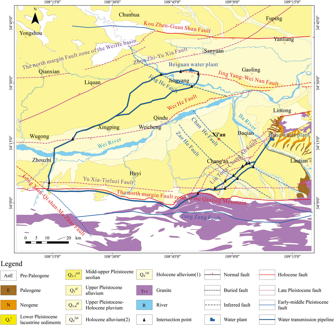
FIGURE 1. Geological conditions of the project (Deng, 2017).
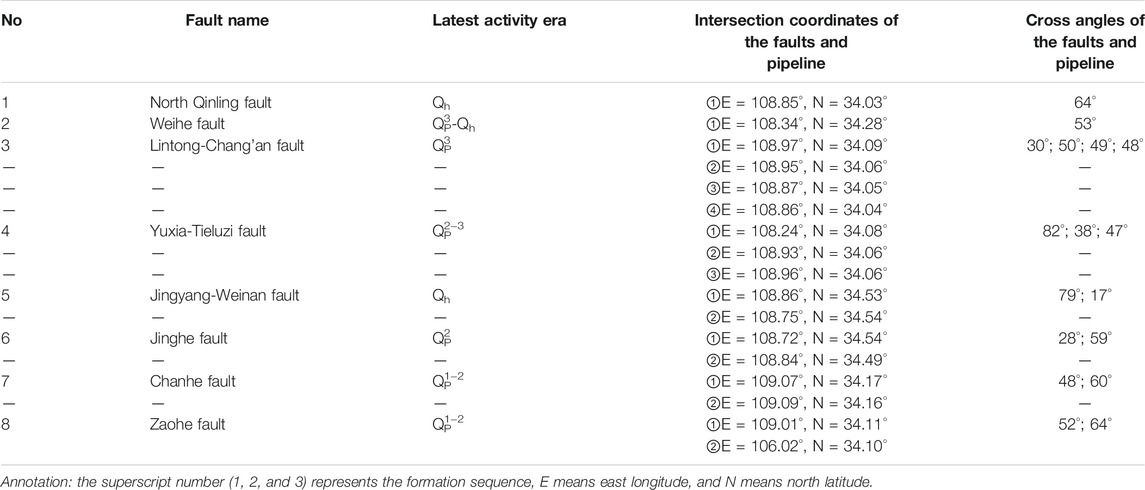
According to the seismic tectonic background, a total of 20 faults developed in the near-field regions, among which seven are Holocene (Qh) faults and eight are Late Pleistocene (Qp) faults. The project intersects with eight of the faults (Deng, 2017). The fault names, intersection point coordinates, cross angles, and latest activity eras of the eight faults are shown in Table 1.
The soil category of the site is evaluated as medium-hard (category II). The peak seismic acceleration of the ground was calculated by adopting the probability analysis of the seismic risk method. According to the calculation results, the peak ground acceleration for exceeding probabilities of 63, 10, 5, and 2% in 50 years is 76–86 Ga l, 200–240 Ga l, 260–310 Ga l, 330–420 Ga l, respectively, and the peak ground acceleration for exceeding probabilities of 5, 2, and 1% in 100 years is 312–384 Ga l, 347–485 Ga l, and 450–630 Ga l, respectively (Deng, 2017). The distribution of peak ground seismic acceleration for typical exceeding probabilities is presented in Figure 2. The seismic precautionary intensity for the project is VIII degrees.
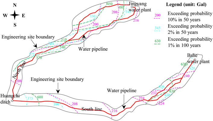
FIGURE 2. Distribution of peak ground acceleration for typical exceeding probabilities (Deng, 2017).
Consequently, the geological tectonic activities are intense in the engineering regions. High seismic intensity regions are distributed widely. Eight large-scale regional faults are intersected, and the investigation of faults' effect on water pipe construction is critical. To date, the influence of fault creep-sliding activities and stick-slip movements on engineering has been extensively considered, and many significant results have been obtained to provide a reference for engineering construction. However, due to the influence of discontinuous interfaces and broken geotechnical structures, the seismic response is generally amplified significantly near the fault belts, which was generally ignored in actual projects, possibly inducing a severe geologic hazard risk on the engineering structures. The dynamic response characteristics and mechanism of the water pipeline crossing the fault zone are significant for the seismic fortification of the project. Consequently, the vibration table test was adopted to study a water pipeline’s seismic response crossing the fault zone, with which the response characteristics of acceleration and stresses in the surrounding soil, dynamical strain on the pipe shell, seismic amplification coefficient and influence scope of fault belt, etc., were elucidated.
Design of the Vibration Table Test
Model Design, Monitoring Scheme, and Material Parameters
According to the project data, the pipeline is made of concrete, and the cross-section is generally circular with an outer diameter of 5.0 m and pipe wall thickness of 0.2 m. The depth of the pipeline in loess is mainly 1.0–2.0 m and can reach 7.0–8.0 m near some steep slope. An enormous depth at the intersection of the north Qinling fault is approximately 80.0 m, which is the geomorphic boundary of Qinling and pluvial fans. The involving eight faults of the project are all positive faults which dip angle are basically 70–80.
An appropriate model size is essential to obtain a reliable result for the vibration table test. Due to the limitations of the width, length, and power of the vibration table, it is challenging to implement physical model tests of a large size. Comprehensively analyzing the similarity ratio, embedment depth and capacity of the vibration table, the geometric similarity ratio was finally designed to be 1:20, with which the outer diameter of the model pipe is 25.0 cm and the water pipe depth was finally determined at 40.0 cm. The outer dimensions of the model box were considered to be 2.8 m × 1.1 m × 1.4 m.
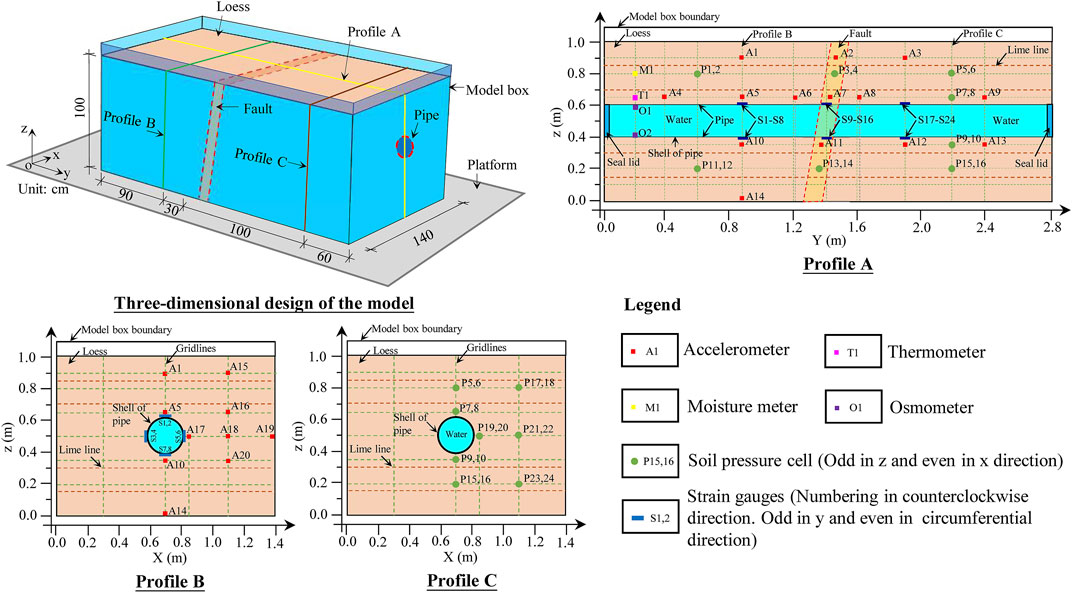
The frame of the physical model box was welded using profile steel. The sides of the box are four pieces of Plexiglas, and the bottom is a sheet of steel plate. A steel hoop and eight vertical reinforcement bars were installed around the box to maintain the stiffness of the model box during the experiment. Four pieces of foam boards with a thickness of 8.0 cm were installed around the box’s inner sides to reduce the boundary’s influence on the dynamical response. The dip angle and width of the fault were designed at 80° and 20.0 cm for the experiment, respectively. A steeper dip angle was adopted considering the actual occurrence of involved faults, size limitation and boundary influences of the vibration table test. The dimensions, distribution of sensors, and details of the critical profiles of the vibration table experiment are presented in Figure 3.
A total of 21 accelerometers, 24 soil pressure cells, 24 strain gauges, 2 osmometers, 1 thermometer, and one moisture meter were installed in the model. The accelerometer is an EY version with a monitoring range of 0.0–2.0 g, a sensitivity coefficient of 451.92 mV/g, and a size of 16 × 15 × 8 mm³. The soil pressure cell (model: BWM) has a monitoring range of 0.0–0.1 MPa, an accuracy of ±0.3 F.S, a diameter of 28 mm, and a thickness of 6.5 mm. The strain gauge (model: 120–5AA) shows a monitoring range of ±50,000 με, a sensitivity coefficient of 2.0 ± 1%, a length of 8.5 mm, and a width of 3.6 mm. The osmometer(model: BWMK) has a monitoring range, accuracy, diameter, and thickness of 0–100 kPa, ±0.01 kPa, 15.8 mm, and 21 mm, respectively. The model of moisture meter and thermometer are CS655 and Campbell 257, respectively. The monitoring direction is x for acceleration, x and z for soil pressure, and y and circumference for the strain gauge.
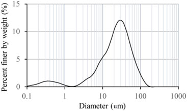
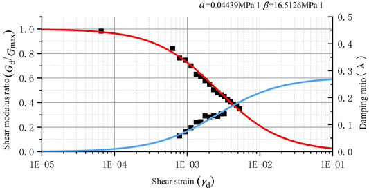
The water pipeline’s surrounding soil is remolding loess, and the fault zone component is a mixture of sawdust and fine sand. The tube was full of water, and both ends were sealed with a lid. To avoid pipe rupture and water leakage under strong vibration, a Polyvinyl Chloride (abbreviation as PVC) plastic pipe with appropriate plasticity and flexibility is adopted for the experiment. The physical and mechanical parameters of loess, PVC pipe, and fault zone soil are shown in Table 2. The distribution of particle size and dynamical parameters are presented in Figure 4 and Figure 5, respectively. The symbols α and β in Figure 5 are the loess test parameters of Hardin model.
Loading Scheme
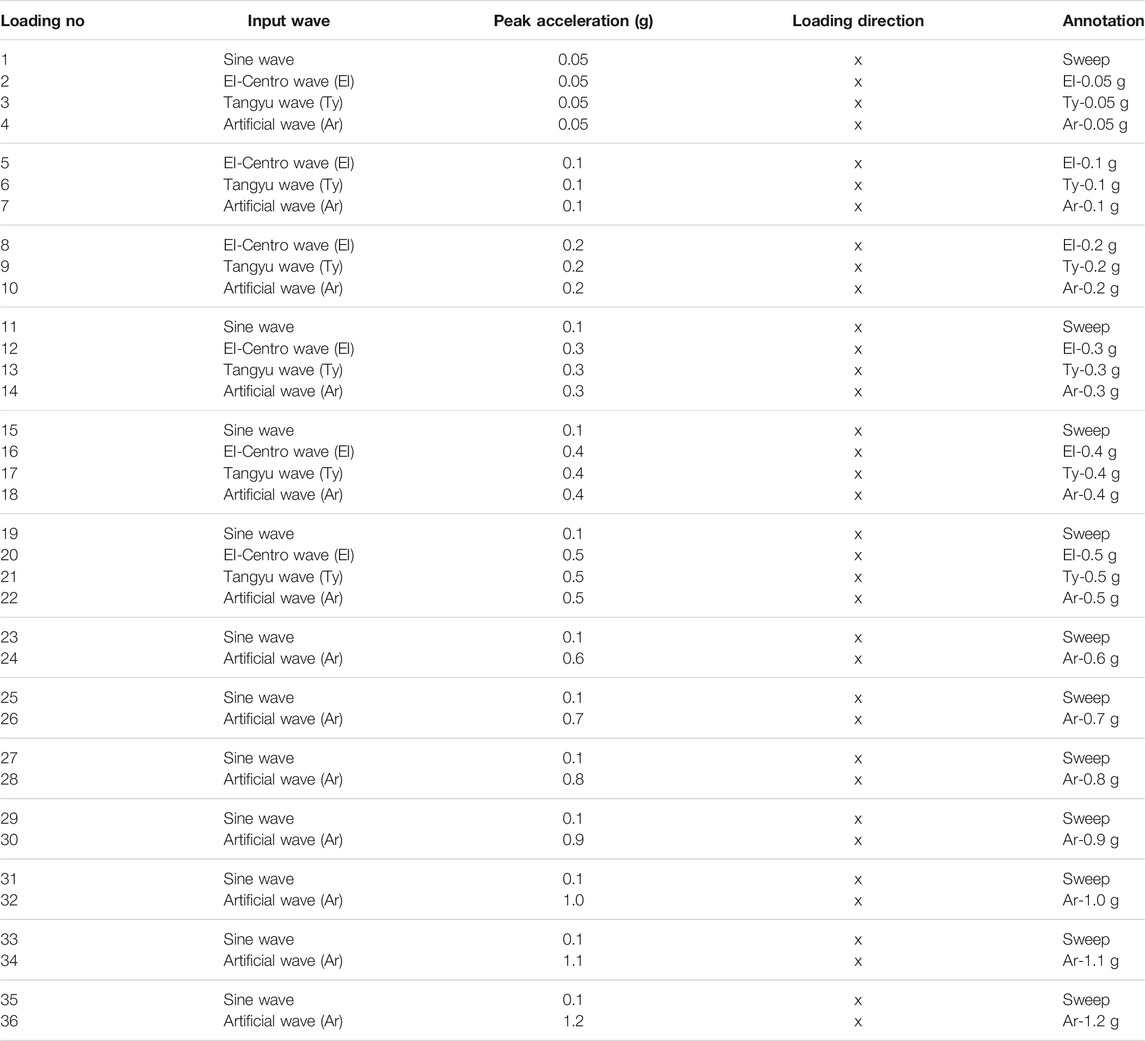
The amplitude, excellent frequency, and effective duration of the time history are the critical factors of seismic waves, significantly influencing the results of the dynamical response. For the comparative analysis, three time-histories were chosen as the excitation wave: the EI-Centro wave (EI), Tangyu wave (Ty), and artificial wave (Ar). The EI wave represents the seismic time history characteristics of a long-distance earthquake for the engineering site. The Ty wave, recorded at the Tangyu seismic station in the Wenchuan earthquake (data sources: National Earthquake Data Center of China), represents the influence of a major historical earthquake on the project. The Ar wave is an artificial seismic wave, which was calculated from the intersection site of the Qinling fault adopting the method of probability analysis of seismic risk, with an exceeding probability of 10% in 50 years. The Ar wave represents the characteristics of potential seismic waves and can be used for seismic fortification design and construction of the project. Figure 6 shows the excitation loading seismic time histories and corresponding Fourier spectrum. Table 3 presents the loading scheme in detail.
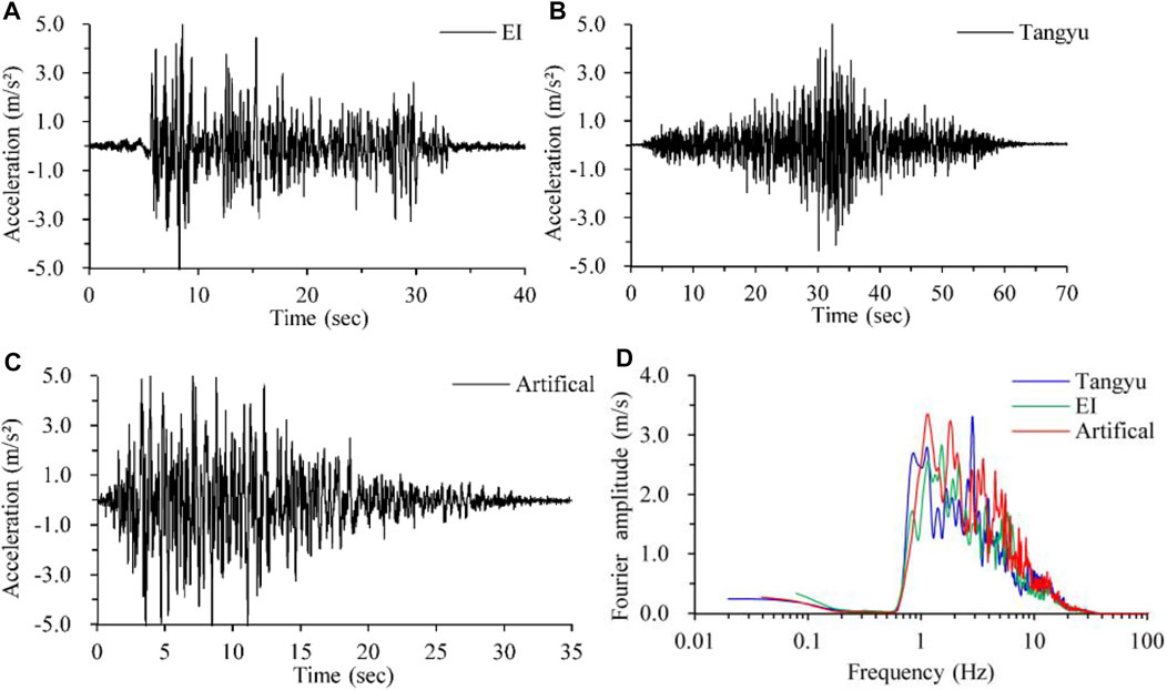
FIGURE 6. Condition of the excitation waves. (A) Time history of EI-Centro wave. (B) Time history of Tangyu waves from the Wenchuan earthquake (data sources: National Earthquake Data Center of China). (C) Time history of the artificial wave. (D) Fourier spectrum of the excitation wave.
Acceleration Dynamic Response
Distribution Characteristics of Acceleration Response
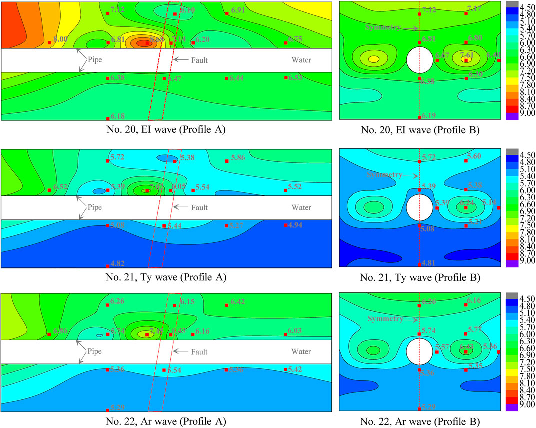
Peak acceleration is one of the most critical parameters for seismic load and ground motions. According to the results of the vibration table test, the acceleration time histories were recorded at the monitoring points, with which the peak accelerations were obtained. Typical longitudinal and transverse profiles A and B were selected to depict the peak acceleration distribution contours adopting the least square method. Because of the similarity of contours under various loadings, only partial results are presented as a description in Figure 7.
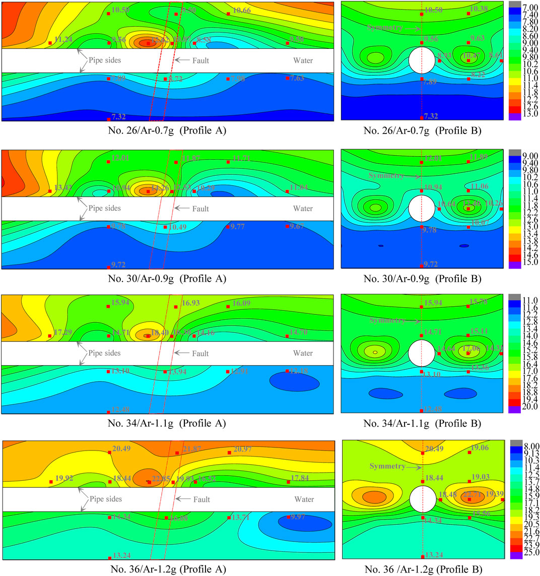
FIGURE 7. Distribution characteristics of the peak acceleration response on profiles A and B (unit: m/s2).
The contours of profile A show that a more considerable peak acceleration generally appears in the hanging wall, especially near the fault zone. The peak acceleration increases gradually with increasing z value. The maximum value is generally distributed close to the upper edge of the pipe located near the fault zone. For a certain depth, the larger and smaller peak accelerations are generally distributed near the fault zone located in the hanging and footwall, respectively. The range of acceleration variation influenced by the fault is approximately 2b in the hanging wall, 1b in the footwall, and 4b in total, where b is the fault zone width. For profile B, a larger peak acceleration was recorded on both sides of the pipeline and is even approximatively equal to the maximum value obtained near the top surface, which might be induced by the significant difference in stiffness between the pipe and surrounding soil.
The central line of profile B was selected, involving four accelerometers numbered A1, A5, A10, and A14, of which the peak acceleration values under various levels of excitation were then obtained. Figure 8A presents the distribution of peak acceleration versus depth, and Figure 8B shows the variation in the amplification factor with depth. The responsive peak acceleration generally increases with increasing z value and peak excitation acceleration. The increase rate is more significant in the regions above the pipe relative to the lower part. A more apparent increase appears when the amplitude of excitation acceleration is more remarkable, which should relate to the influence of cracking and soil failure under shock. The amplification factor of the peak acceleration with depth can reach 1.2–1.6 when the location is close to the top surface of the model.
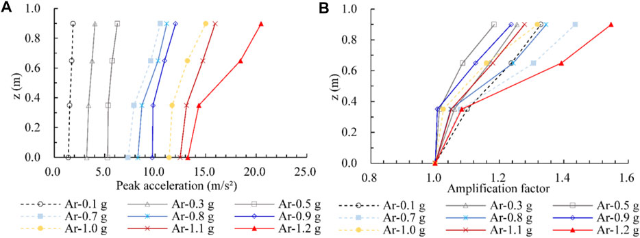
FIGURE 8. Peak acceleration response curves for various depth. (A) Peak acceleration versus depth, (B) acceleration amplification factor versus depth.
Based on the Fourier transformation, the Fourier spectra of recorded time histories for specific points were obtained. The amplification factor along with depth was denoted by the ratio of A1/A14, A5/A14, and A10/A14. The acceleration response spectrum and corresponding amplification factor along with depth were determined, as shown in Figure 9. The comparison of the Fourier spectrum shows that the amplification factors are significant in the frequency range of 3–225 Hz, but only the range of 3–8 Hz possesses an excellent Fourier spectrum amplitude. Consequently, the amplification of the Fourier spectrum amplitude with depth is mainly concentrated in the frequency range of 3–8 Hz. The amplification of the acceleration response spectrum is concentrated mainly in the period of 0.05–0.5 s, especially in the period of 0.05–0.26 s.
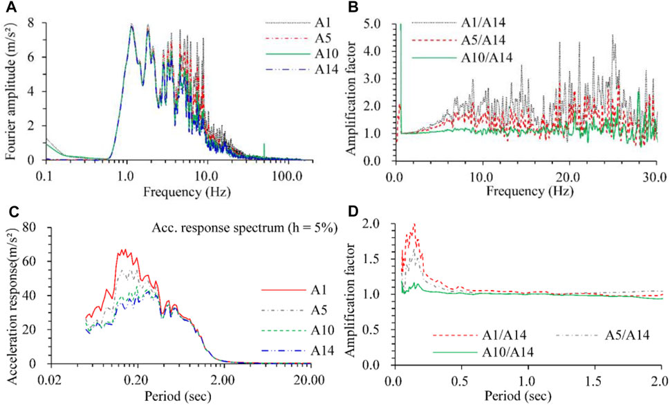
FIGURE 9. Fourier spectrum and response spectrum at No.36–1.2 g. (A) Fourier spectrum of specific points, (B) amplification factor of Fourier spectrum, (C) acceleration response spectrum of specific points, (D) amplification factor of acceleration response spectrum.
Consequently, the peak acceleration amplification is prominent in the range of the fault zone, hanging wall, and nearby the pipe. The fault influence range is approximately four times the fault width. The amplification factor of peak acceleration with depth can reach 1.2–1.6, mainly induced by seismic waves with a frequency range of 3–8 Hz. The amplification of the acceleration response spectrum concentrates primarily in 0.05–0.26 s.
Influence of Fault on Acceleration Response
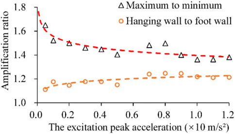
For quantifying the effect of faults on peak acceleration distributions, the amplification ratio was defined and calculated. Based on the contours, the maximal, minimal, and general values of peak accelerations at a depth of z = 0.65 m were extracted, with which the amplification ratios of maximum to minimum and the hanging wall mean to footwall mean were calculated, respectively. The result is presented in Figure 10. The ratio of maximum to minimum decreases gradually with increasing excitation acceleration. The maximum ratio tends to 1.8 when the input peak acceleration approaches zero, the minimum ratio tends to 1.35 when the excitation reaches 1.2, and the amplification ratio approximates 1.5 when the excitation adopts an exceeding probability of 10% in 50 years of the engineering site. The ratio of the hanging wall to the footwall increases gradually with increasing excitation peak acceleration, and the increase rate is maintained at a relatively small level of approximately 1.2.
The fault zone affects not only the responsive peak acceleration but also the frequency of the time history. The acceleration Fourier spectra and response spectra recorded at specific points are presented in Figure 11 and Figure 12, respectively. According to the Fourier spectra, the excellent frequencies are mainly in the range of 1–10 Hz. The Fourier amplitude ratios of A5, A6, A7, and A8 to A9 were calculated and are presented in Figure 11C. The amplification ratios are approximately constant for a certain monitoring point when the frequency falls into the frequency range of 1–6 Hz, fluctuate slightly when the frequency is equal to 6–10 Hz and fluctuate significantly when the frequency is greater than 10 Hz. In the excellent frequency range of 1–10 Hz, the amplification ratio of the Fourier spectrum is approximately 1.3 at point A6 and 1.1–1.2 at points A5, A7, and A8. In addition, the changes in excitation peak acceleration have a small impact on the amplification ratios of the Fourier spectrum, which is presented in Figure 11C, D. The acceleration response spectra are calculated adopting the damping ratio of h = 5% and time histories of specific points, which are shown in Figure 12A. The diversity is remarkable in the period of 0.05–2.0 s, especially in the period of 0.1–1.0 s. The response spectrum ratios of A5, A6, A7, and A8 to A9 are calculated and presented in Figure 12B. The ratios are approximately constant in the period of 0.1–2.0 s and attenuate rapidly when the period is greater than 2.0 s. The amplification ratio reaches 1.25–1.30 for the A6 point in the platform part.
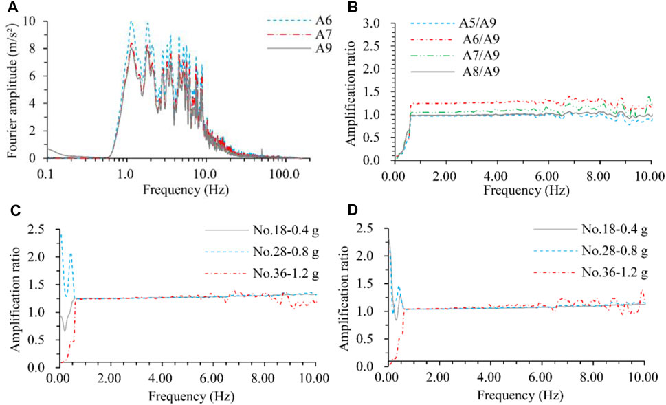
FIGURE 11. Fourier spectrum and fault amplification ratio. (A) Fourier spectrum of specific points at loading No.36–1.2 g, (B) Amplification ratio of Fourier spectrum at loading No.36–1.2 g, (C) Amplification ratio of Fourier spectrum at point A6, (D) Amplification ratio of Fourier spectrum at point A7.

FIGURE 12. Acceleration response spectrum and amplification ratio of fault at loading No. 36–1.2 g. (A) Acceleration response spectrum for specific points, (B) Amplification ratio of acceleration response spectra.
Consequently, the acceleration amplification ratio in the fault zone generally exceeds 1.35, even up to 1.8, and the hanging wall amplification ratio is approximately 1.2. The magnification ratio of faults on the Fourier spectrum and response spectrum can reach 1.3, mainly in the range of excellent frequency and period.
Influence of Excitation Waves on Acceleration Response
The spectrum characteristics and effective durations of excitation waves will significantly influence the dynamic response. The responsive peak acceleration contours for different excitation waves with the same amplitude are presented in Figure 13. Figure 14 shows the comparison of responsive peak acceleration versus depth. Although the specific data of responsive peak acceleration vary for different excitations, the distribution characteristics and variation laws are always the same. The acceleration responses triggered by the EI wave are generally better than those triggered by the Ar and Ty waves. The acceleration amplification ratio on depth is defined as the ratio of peak acceleration at a certain depth to that of the model’s bottom, which varies with the change of excitation waves and amplitude.
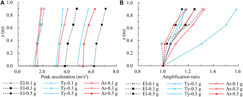
FIGURE 14. Comparison of peak acceleration response for different excitation waves, (A) peak acceleration versus depth, and (B) acceleration amplification ratio versus depth.
The Fourier spectrum of the time histories recorded at A1 is highly similar to that of the corresponding excitation wave, as shown in Figure 15A and Figure 6D. The Fourier spectrum ratio of A1 to A14 was calculated and is presented in Figure 15B, which shows slight amplification when the frequency is in the 15–35 Hz range, significant amplification when the frequency is equal to 50 Hz, and almost identical amplification when the frequency is in the range of excellence. The corresponding response spectrum was calculated adopting a damping ratio of 5%, with which the amplification ratio of A1/A14 was obtained, as shown in Figure 15C, D. A great disparity is shown for the response spectrum when the period is in the 0.05–2.0 s range. The amplification ratio of the response spectrum varies considerably when the period is in the 0.05–0.2 s range.
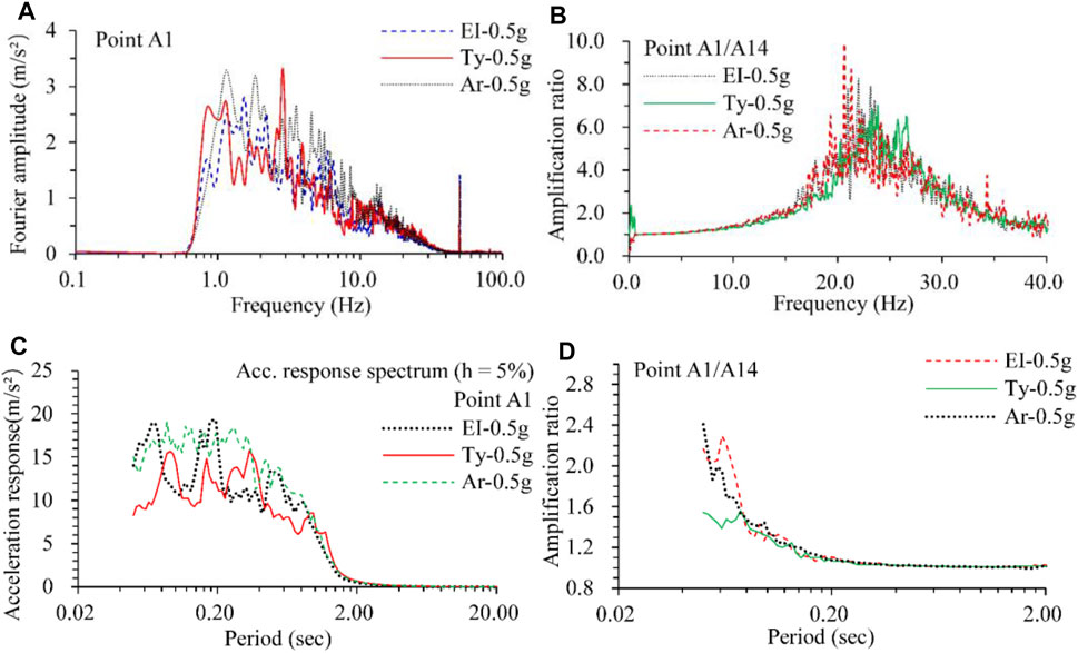
FIGURE 15. Comparison of Fourier spectrum and response spectrum, (A) Fourier spectrum of time history recorded at point A1, (B) the Fourier spectrum ratio of A1 to A14, (C) response spectrum of the time history recorded at A1, (D) the response spectrum ratio of A1 to A14.
Dynamic Response Characteristics of the Soil Stress
Dynamic pressures or stresses in the soil are critical parameters that significantly affect the site deformation and stability under earthquake. The value, distribution, and variation of dynamic soil stresses are generally influenced by the peak acceleration of excitation, stratum lithology, soil density, burial depth, and features of the embedded structures, etc. The monitoring of dynamic soil stresses is critical for the evaluation, prevention, and mitigation of seismic disasters for foundation engineering. Soil pressure cells with various locations and orientations were designed and embedded in the vibration table test. The distribution of soil pressure cells is presented in Figure 3. The time history curves of dynamical soil stresses for typical points are shown in Figure 16. The peak soil stresses versus excitation accelerations are presented in Figure 17.
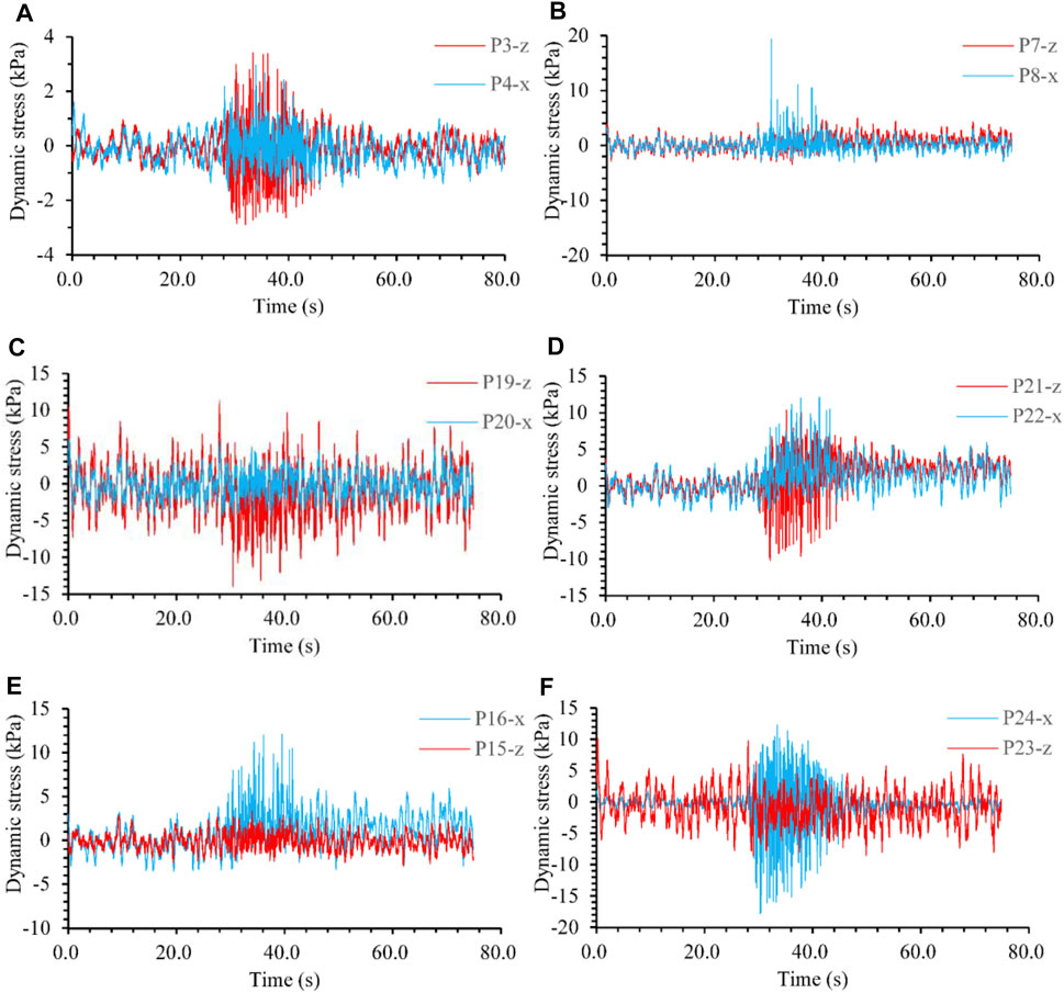
FIGURE 16. Time history curves of dynamic stress in soil (loading No. 34, 1.1 g of the excitation peak acceleration). (A) stress at P3 and P4, (B) stress at P7 and P8, (C) stress at P19 and P20, (D) stress at P21 and P22, (E) stress at P15 and P16, and (F) stress at P23 and P24.

FIGURE 17. The peak stresses in soil versus the excitation acceleration. (A) Stresses in the x direction and (B) stresses in the z direction.
According to the recorded results, the stresses in soil respond to the excitation sensitively, nonlinearly, and nonuniformly in both directions x and z. During a specific loading, the amplitude of responsive stress increases remarkably when the peak of excitation acceleration arrives. The envelope lines of the responsive stress time-history curves approximatively synchronize with that of the excitation acceleration for most monitoring points. The responsive stress amplitude generally increases with increasing excitation, and the increase rate is more significant when the input peak acceleration is greater, especially for the regions near the pipeline and close to the model bottom. Regardless, the distribution of responsive dynamic stress in the surrounding soil is complicated and mainly affected by the excitation acceleration and specific structural characteristics in the model. Due to the influence of nonuniform deformations, the structure and soil contact zone will raise considerable dynamic stresses.
Dynamic Strain Response of the Pipe
The pipeline strain response under earthquake could reflect the dynamic micro-deformation characteristics, potential damage location, range, model of the pipeline, etc., to a great extent. Dynamic strain monitoring could provide important information and data conducive to the stress analysis and seismic-resistant design of pipeline axial and crossing sections.
In this experiment, a total of 24 strain gauges were affixed in three cross-sections of the pipeline with horizontal ordinates of y = 0.9 m, 1.4 m, and 1.9 m. The strain gauges numbered S1-S8 are for Section I (y = 0.9 m), among which S1 and S2 lie at the pipeline top, S7 and S8 are located at the pipeline bottom, and S3-S6 are on both sides of the pipeline. All the strain gauges appear in pairs, where the odd numbers are for axial (y) direction, and even numbers are for circumferential direction. S9-S16 and S17-S24 belong to sections II (y = 1.4 m) and III (y = 1.9 m), respectively, and the numbering sequence and rules are consistent with those of Section I. The distribution of strain gauges is shown in Figure 3.
Although the specific data and strain time-history curves generally vary from points to points and are greatly dependent on the monitoring locations, loading conditions, etc., the overall characteristics are always the same. Consequently, only typical monitoring results are selected as an illustration. Figure 18A presents the responsive dynamic strain time-history curves of S5 and S6 with an excitation peak acceleration of 1.2 g. Although the seismic load acting on the bottom of the model is just in the x-direction, the dynamic strain of the pipeline responds obviously in both the axial (y-direction) and circumferential directions. During a specific level of loading, the strain response increases greatly when t = 35–60 s. The mean lines of the strain time-history curves tend to a small negative value for S5 and an apparent negative value for S6, which indicates that this point is in a compressive state, with a bending deformation tendency along the axial and circumference directions. The peak acceleration of excitation versus the maximum (positive value represents the tensile state) and minimum (negative value refers to the compressive state) responsive strain of typical points is shown in Figure 18B. The peak strain generally increases gradually with increasing excitation. The variation rate increases quickly for S6 when the acceleration is more significant than 1.0 g, which indicates that a large bending deformation is produced along the circumference. Figure 18C, D show the variation in strain along the axial direction of the pipe bottom and a pipe side, respectively. The maximum strain generally appears in the fault zone, and the peak value significantly decreases from the midpoint to both ends of the pipeline. According to the distribution characteristics of axial strain, bending deformation occurs along the pipeline in both the vertical and horizontal directions. Figure 18E, F show the variation of circumferential strain along the cross-section of y = 1.4 m and y = 0.9 m. The pipeline mainly undergoes expansion and shrinkage deformation in the radial direction. In the cross-section of y = 1.4 m, the pipeline shows an approximate symmetrical deformation. The maximum tensile and compressive strain occurs at the top and bottom of the pipeline, respectively. In the cross-section of y = 0.9 m, the deformation is asymmetric with a more significant value at the pipe bottom.
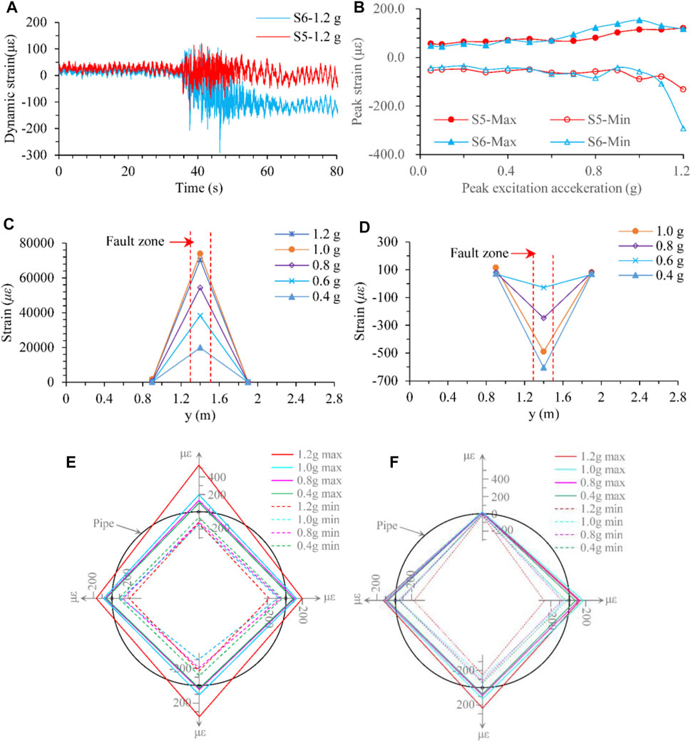
FIGURE 18. Responsive dynamic strain of the pipe. (A) Strain time-history curves of typical monitoring points, (B) peak of responsive strain versus excitation acceleration, (C) peak axial strain variation along the pipe bottom, (D) peak axial strain variation along the pipe side, (E) peak circumferential strain along the cross-section of y = 1.4 m, (F) peak circumferential strain along the cross-section of y = 0.9 m.
Consequently, under the action of an earthquake, the water-filled pipeline crossing a fault zone primarily undergoes bending deformation along the axial direction, accompanied by expansion and shrinkage in the radial direction. The maximum tensile and compressive strain occur at the central section of the pipe in the fault zone.
Crack Characteristics of the Soil
Understanding the failure process and mechanism of the engineering site under excitation is one of the most significant and applicable results from the vibration table test. It was possible to discern the vulnerable regions by analyzing the crack characteristics, and the methods of mitigation damage for the engineering could be obtained.
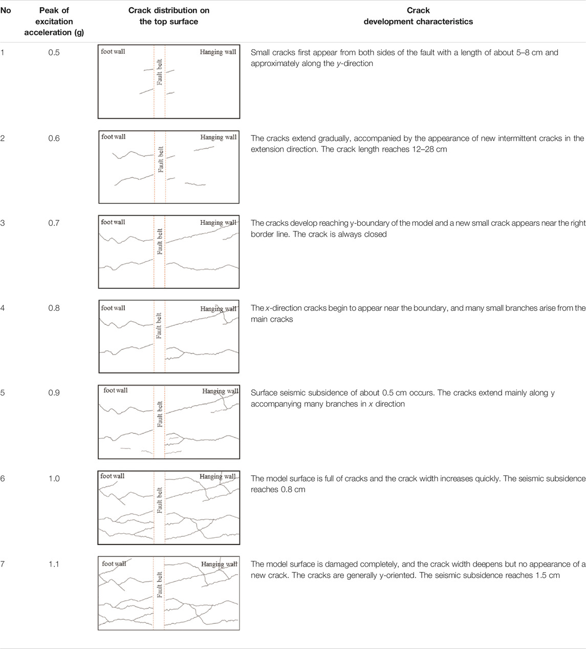
The crack characteristics of the model top surface are presented in Table 4. Small cracks first appeared from both sides of the fault when the excitation peak acceleration reached 0.5 g. The quantity, length, width, and depth of the cracks increased gradually with increasing excitation acceleration amplitude. The cracks originated from both sides of the fault asymmetrically, which should relate to the distribution characteristics of responsive acceleration and fault amplification. Meanwhile, the cracks all develop along the y-direction, which may be affected by the model’s inconsistent stiffness between the rigid boundary, structure, and soil. Slight seismic collapses occur in the unsaturated loess site when the excitation peak acceleration is excellent, reaching 1.0 g.
Discussion
Strata in the fault zone sites related to this project vary and generally involve interbedded layers of loess and paleosol. However, the consideration of strata variation would cause an obvious complexity in the test design because a large number of sensors have to be arranged near the discontinuous interface to monitor the dynamic response. Too many sensors and wires would be embedded, which would influence the model structural uniformity and increase the costs significantly. More importantly, this study mainly focuses on the dynamic response characteristics of the water pipeline crossing a fault, and ignoring strata variation might result in a more apparent influence law for the fault. Consequently, the stratum was designed as uniform loess in the vibration table test.
We also monitored the dynamic response of the water pressure inside the pipeline. The distribution histograms and curves are presented in Figure 19. The dynamic response of water pressure is generally close to zero with a few occasional impulses. The impulse amplitude reaches 10 kPa for sensor O1 and 300 kPa for O2. The dynamic water pressure of O2 is significantly greater than that of O1. Although the shear waves cannot propagate in the water inside the pipe, tremendous dynamic water pressure still occurred due to the influence of the impulses.
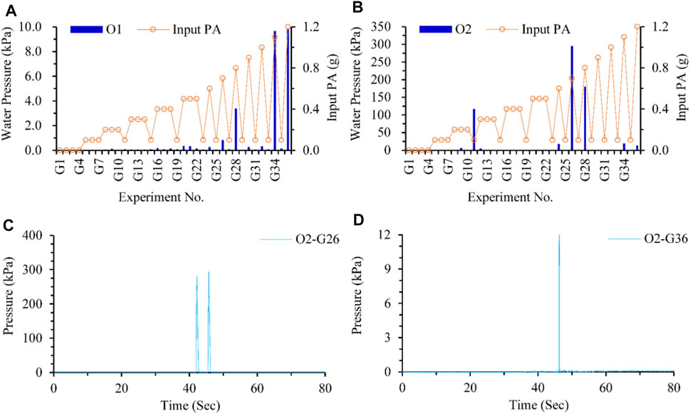
FIGURE 19. Dynamic water pressure response inside the pipeline. (A) Water pressure response of O1 under various loadings. (B) Water pressure response of O2 under various loadings. (C) Water pressure response of O2 under G26. (D) Water pressure response of O2 under G36.
Conclusion
A large-scale vibration table test was adopted to investigate the seismic response of the water transmission pipeline crossing the fault. The responses of accelerations, dynamic stresses, strains, and water pressures for the pipeline and surrounding loess were obtained. The results are presented as follows.
1) The dynamic response is significantly amplified in the fault zone and hanging wall. The fault influence range is approximately four times the fault width. The maximum acceleration amplification ratio in the fault zone generally exceeds 1.35, reaches up to 1.8, and approximates 1.5 when excitation is adopted with an exceeding probability of 10% in 50 years. The ratio of the hanging wall to the footwall is maintained at a relatively slightly small level of approximately 1.2. The spectrum characteristics and effective durations of excitation waves also significantly influence the dynamic response.
2) The distribution of responsive dynamic stresses in the surrounding soil is complicated and mainly affected by the excitation acceleration properties and specific structural characteristics in the model. Due to the influence of nonuniform deformations, the structure and soil contact zone will raise considerable dynamic stresses.
3) The pipeline mainly undergoes bending deformation along the axial direction, accompanied by expansion and shrinkage in the radial direction. The maximum tensile and compressive strain occur at the central section of the pipe in the fault zone. Massive cracks developed along the y-direction, accompanied by slight seismic subsidence.
The research findings could provide reasonable parameters for the seismic design and construction of the project.
Data Availability Statement
The original contributions presented in the study are included in the article/Supplementary Material, further inquiries can be directed to the corresponding authors.
Author Contributions
WF proposed and participated in designing the study; YD participated in implement the test; SR participated in implement the test; PL participated in dealing with the data; All authors approved the final version of the manuscript.
Funding
This study was sponsored by the National Natural Science Foundation of China (grant numbers 41877245 and 41630634), Open Foundation of China Railway First Survey and Design Institute Group Co., Ltd (SPS-D-04), and Natural Science Foundation of Shaanxi Province (grant numbers 2021JQ-243).
Conflict of Interest
The authors declare that the research was conducted in the absence of any commercial or financial relationships that could be construed as a potential conflict of interest.
Author WZ and YL are employed by China Railway First Survey and Design Institute Group Co., Ltd. All authors declare no other competing interests.
Publisher’s Note
All claims expressed in this article are solely those of the authors and do not necessarily represent those of their affiliated organizations, or those of the publisher, the editors and the reviewers. Any product that may be evaluated in this article, or claim that may be made by its manufacturer, is not guaranteed or endorsed by the publisher.
References
Abdoun, T. H., Ha, D., O’Rourke, M. J., Symans, M. D., O’Rourke, T. D., Palmer, M. C., et al. (2009). Factors Influencing the Behavior of Buried Pipelines Subjected to Earthquake Faulting. Soil Dyn. Earthquake Eng. 29, 415–427. doi:10.1016/j.soildyn.2008.04.006
Bao, Z., Yuan, Y., and Yu, H. (2017). Multi-scale Physical Model of Shield Tunnels Applied in Shaking Table Test. Soil Dyn. Earthquake Eng. 100, 465–479. doi:10.1016/j.soildyn.2017.06.021
Chen, J., Jiang, L., Li, J., and Shi, X. (2012). Numerical Simulation of Shaking Table Test on Utility Tunnel under Non-uniform Earthquake Excitation. Tunnelling Underground Space Technol. 30, 205–216. doi:10.1016/j.tust.2012.02.023
Chiou, Y.-J., Chi, S.-Y., and Chang, H.-Y. (1994). A Study on Buried Pipeline Response to Fault Movement. J. Press. Vessel Technol 116, 36–41. doi:10.1115/1.2929556
Corigliano, M., Scandella, L., Lai, C. G., and Paolucci, R. (2011). Seismic Analysis of Deep Tunnels in Near Fault Conditions: a Case Study in Southern Italy. Bull. Earthquake Eng. 9, 975–995. doi:10.1007/s10518-011-9249-3
Demirci, H. E., Bhattacharya, S., Karamitros, D., and Alexander, N. (2018). Experimental and Numerical Modelling of Buried Pipelines Crossing Reverse Faults. Soil Dyn. Earthquake Eng. 114, 198–214. doi:10.1016/j.soildyn.2018.06.013
Deng, L. S. (2017). Earthquake Safety Evaluation Report of the Hanjiang-To-Weihe River Diversion Project (Phase II). Xi'an, China: Chang’An university.
Dezhkam, B., and Nouri, A. Z. (2018). Dynamic Response of Nanoparticle-Water Pipes Buried in the Soil Subjected to Far-Fault Earthquake Using Numerical Method. Soil Dyn. Earthquake Eng. 113, 174–179. doi:10.1016/j.soildyn.2018.06.002
Dhakal, Y. P. (2021). Strong-motions from Damaging Moderate Magnitude (5.9 ≥ Mw) Earthquakes in Japan Recorded by K-NET and KiK-Net. Front. Earth Sci. 9, 618400. doi:10.3389/feart.2021.618400
Duan, M.-l., Mao, D.-f., Yue, Z.-y., Estefen, S., and Li, Z.-g. (2011). A Seismic Design Method for Subsea Pipelines against Earthquake Fault Movement. China Ocean Eng. 25, 179–188. doi:10.1007/s13344-011-0016-7
Fadaee, M., Farzaneganpour, F., and Anastasopoulos, I. (2020). Response of Buried Pipeline Subjected to Reverse Faulting. Soil Dyn. Earthquake Eng. 132, 106090. doi:10.1016/j.soildyn.2020.106090
Fard, S. S., Nekooei, M., Oskouei, A. V., and Aziminejad, A. (2019). Experimental and Numerical Modeling of Horizontally-Bent Buried Pipelines Crossing Fault Slip. Lat. Am. J. Solids Struct. 16, e175. doi:10.1590/1679-78255463
Gantes, C. J., and Melissianos, V. E. (2016). Evaluation of Seismic protection Methods for Buried Fuel Pipelines Subjected to Fault Rupture. Front. Built Environ. 2, 34. doi:10.3389/fbuil.2016.00034
Hall, W. J., Nyman, D. J., Johnson, E. R., and Norton, J. D. (2003). “Performance of the Trans-Alaska Pipeline in the November 3, 2002 Denali Fault Earthquake,” in Advancing Mitigation Technologies and Disaster Response for Lifeline Systems, 522–534. doi:10.1061/40687(2003)54
Hashash, Y. M. A., Hook, J. J., Schmidt, B., I-Chiang Yao, J., and Yao, C. (2001). Seismic Design and Analysis of Underground Structures. Tunnelling underground Space Technol. 16, 247–293. doi:10.1016/s0886-7798(01)00051-7
Honegger, D. G., Nyman, D. J., Johnson, E. R., Cluff, L. S., and Sorensen, S. P. (2004). Trans-Alaska Pipeline System Performance in the 2002 Denali Fault, Alaska, Earthquake. Earthquake spectra 20, 707–738. doi:10.1193/1.1779239
Joshi, S., Prashant, A., Deb, A., and Jain, S. K. (2011). Analysis of Buried Pipelines Subjected to Reverse Fault Motion. Soil Dyn. Earthquake Eng. 31, 930–940. doi:10.1016/j.soildyn.2011.02.003
Karamitros, D. K., Bouckovalas, G. D., Kouretzis, G. P., and Gkesouli, V. (2011). An Analytical Method for Strength Verification of Buried Steel Pipelines at normal Fault Crossings. Soil Dyn. Earthquake Eng. 31, 1452–1464. doi:10.1016/j.soildyn.2011.05.012
Kennedy, R. P., Short, S. A., and Darrow, A. C. (1979). Seismic Design of Oil Pipeline Systems. J. Tech. Counc. ASCE 105, 119–134. doi:10.1061/jtcad9.0000022
Kiani, M., Akhlaghi, T., and Ghalandarzadeh, A. (2016). Experimental Modeling of Segmental Shallow Tunnels in Alluvial Affected by normal Faults. Tunnelling Underground Space Technol. 51, 108–119. doi:10.1016/j.tust.2015.10.005
Liang, J., and Sun, S. (2000). Site Effects on Seismic Behavior of Pipelines: a Review. J. Press. Vessel Technol 122, 469–475. doi:10.1115/1.1285974
Newmark, N. M., and Hall, W. J. (1975). “Pipeline Design to Resist Large Fault Displacement,” in Proceedings of US national conference on earthquake engineering, 416–425.
Peng, D., Yueren, X., Qinjian, T., and Wenqiao, L. (2021). Using Google Earth Images to Extract Dense Landslides Induced by Historical Earthquakes at the Southwest of Ordos, China. Front. Earth Sci. 8, 633342. doi:10.3389/feart.2020.633342
Sarvanis, G. C., Karamanos, S. A., Vazouras, P., Mecozzi, E., Lucci, A., and Dakoulas, P. (2018). Permanent Earthquake-Induced Actions in Buried Pipelines: Numerical Modeling and Experimental Verification. Earthquake Engng Struct. Dyn. 47, 966–987. doi:10.1002/eqe.3001
Shen, Y. S., Wang, Z. Z., Yu, J., Zhang, X., and Gao, B. (2020). Shaking Table Test on Flexible Joints of Mountain Tunnels Passing through normal Fault. Tunnelling Underground Space Technol. 98, 103299. doi:10.1016/j.tust.2020.103299
Shi, J., Wang, Y., and Chen, Y. (2018). A Simplified Method to Estimate Curvatures of Continuous Pipelines Induced by normal Fault Movement. Can. Geotech. J. 55, 343–352. doi:10.1139/cgj-2017-0044
Sun, S. (1991). in Earthquake Damages of Pipelines in China, Earthquake Resistance of Buried Pipelines. Editor Z. Hou (Beijing: Academic Press), 1–9.
Sun, S., and Shien, S. (1983). “Analysis of Seismic Damage to Buried Pipelines in Tangshan Earthquake,” in Earthquake Behavior and Safety of Oil and Gas Storage Facilities, Buried Pipelines and Equipment, PVP-77 (New York: American Society of Mechanical Engineers (ASME)), 365–367.
Toprak, S., and Taskin, F. (2007). Estimation of Earthquake Damage to Buried Pipelines Caused by Ground Shaking. Nat. Hazards 40, 1–24. doi:10.1007/s11069-006-0002-1
Tsinidis, G., Di Sarno, L., Sextos, A., and Furtner, P. (2019). A Critical Review on the Vulnerability Assessment of Natural Gas Pipelines Subjected to Seismic Wave Propagation. Part 2: Pipe Analysis Aspects. Tunnelling Underground Space Technol. 92, 103056. doi:10.1016/j.tust.2019.103056
Tsinidis, G., Di Sarno, L., Sextos, A., and Furtner, P. (2020). Optimal Intensity Measures for the Structural Assessment of Buried Steel Natural Gas Pipelines Due to Seismically-Induced Axial Compression at Geotechnical Discontinuities. Soil Dyn. Earthquake Eng. 131, 106030. doi:10.1016/j.soildyn.2019.106030
Tsinidis, G., Di Sarno, L., Sextos, A., and Furtner, P. (2020). Seismic Fragility of Buried Steel Natural Gas Pipelines Due to Axial Compression at Geotechnical Discontinuities. Bull. Earthquake Eng. 18 (2020), 837–906. doi:10.1007/s10518-019-00736-8
Uckan, E., Akbas, B., Shen, J., Rou, W., Paolacci, F., and O’Rourke, M. (2015). A Simplified Analysis Model for Determining the Seismic Response of Buried Steel Pipes at Strike-Slip Fault Crossings. Soil Dyn. Earthquake Eng. 75, 55–65. doi:10.1016/j.soildyn.2015.03.001
Vazouras, P., and Karamanos, S. A. (2017). Structural Behavior of Buried Pipe Bends and Their Effect on Pipeline Response in Fault Crossing Areas. Bull. Earthquake Eng. 15, 4999–5024. doi:10.1007/s10518-017-0148-0
Wang, L. R.-L., and Yeh, Y.-H. (1985). A Refined Seismic Analysis and Design of Buried Pipeline for Fault Movement. Earthquake Engng. Struct. Dyn. 13, 75–96. doi:10.1002/eqe.4290130109
Wang, X., Guo, E., and Zhang, M. (2012). Analysis and Countermeasures on Seismic Damage to Gas Pipeline in Wenchuan Earthquake. World Earthquake Eng. 28, 44–50.
Yan, K., Zhang, J., Wang, Z., Liao, W., and Wu, Z. (2018). Seismic Responses of Deep Buried Pipeline under Non-uniform Excitations from Large Scale Shaking Table Test. Soil Dyn. Earthquake Eng. 113, 180–192. doi:10.1016/j.soildyn.2018.05.036
Yang, Z., Lan, H., Zhang, Y., Gao, X., and Li, L. (2013). Nonlinear Dynamic Failure Process of Tunnel-Fault System in Response to strong Seismic Event. J. Asian Earth Sci. 64, 125–135. doi:10.1016/j.jseaes.2012.12.006
Keywords: vibration table test, seismic response, pipeline across fault zone, loess site, influence of fault
Citation: Deng L, Zhang W, Dai Y, Fan W, Li Y, Ren S and Li P (2021) Seismic Response of a Water Transmission Pipeline Across a Fault Zone Adopting a Large-Scale Vibration Table Test. Front. Earth Sci. 9:777551. doi: 10.3389/feart.2021.777551
Received: 15 September 2021; Accepted: 04 November 2021;
Published: 24 November 2021.
Edited by:
Yueren Xu, China Earthquake Administration, ChinaReviewed by:
Ming Zhang, China University of Geosciences Wuhan, ChinaLuigi Di Sarno, University of Liverpool, United Kingdom
Copyright © 2021 Deng, Zhang, Dai, Fan, Li, Ren and Li. This is an open-access article distributed under the terms of the Creative Commons Attribution License (CC BY). The use, distribution or reproduction in other forums is permitted, provided the original author(s) and the copyright owner(s) are credited and that the original publication in this journal is cited, in accordance with accepted academic practice. No use, distribution or reproduction is permitted which does not comply with these terms.
*Correspondence: Longsheng Deng, ZGxzaEBjaGQuZWR1LmNu; Wen Fan, ZmFud2VuQGNoZC5lZHUuY24=
 Longsheng Deng
 Wenzhong Zhang3,4