 Yang Yang1
 Longhuan Du
- 1Key Laboratory of Deep Earth Science and Engineering, Sichuan University, Ministry of Education, Chengdu, China
- 2College of Architecture and Environment, Sichuan University, Chengdu, China
- 3Lingchuang Green House Construction Technology Co., Ltd., Chengdu, China
There are a large number of natural fractures in shale reservoirs, which create great challenges to hydraulic fracturing. Activating the natural fractures in reservoirs can form a complex fracture network, enhance fracturing effects, and increase shale gas production. Reservoir geological conditions (low in situ stress, natural fracture distribution, and cement strength) and operation parameters (fracturing fluid viscosity and injection rate) have an important influence on fracture network propagation. In this article, a two-dimensional hydraulic fracturing fluid-mechanic coupling numerical model for shale reservoirs with natural fractures was established. Based on the global cohesive zone model, the influence of geological conditions and operation parameters on the propagation of the hydraulic fracture network and fracturing process is investigated. The numerical simulation results show that when the horizontal in situ stress difference, approach angle, and cement strength are low, it is easier to form a complex fracture network. Research on the construction parameters indicated that when the viscosity of the fracturing fluid is low, it is easier to form a complex network of fractures, but the length of the fractures is shorter; in contrast, the fractures are straight and long. In addition, increasing the injection rate is beneficial for increasing the complexity of the fracture network while increasing the initiation pressure and width of the principal fracture reduces the risk of sand plugging. This article also proposes an optimization solution for hydraulic fracturing operations based on numerical simulation results.
Introduction
Shale gas is a type of unconventional natural gas that exists in shale reservoirs in an adsorbed or free state (Gale et al., 2014; Cheng et al., 2021; Lin et al., 2021). Hydraulic fracturing technology and horizontal well technology are widely employed in shale gas reservoir stimulation engineering (Weng, 2015). Compared to conventional reservoirs, shale reservoirs contain a large number of natural fractures (NFs) and form a series of fracture groups (Liu et al., 2021a). Activating a large number of natural fractures is advantageous for improving the final effect of reservoir stimulation (Mayerhofer et al., 2010; Liu et al., 2020). Therefore, many studies of the influence of NFs on the propagation process of hydraulic fractures (HFs), as well as the final fracture network morphology, have been conducted (Liu et al., 2021b).
In the process of hydraulic fracturing, when an HF encounters an NF, according to the influence on the shape of the seam mesh, the HF usually exhibits the following mechanical behaviors: 1) crossing the NF, 2) arresting by the NF, and 3) offsetting from NF (Wang et al., 2017). Based on a large number of experiments, researchers have summarized the different behaviors of interactions between HFs and NFs under different experimental conditions (Feng et al., 2020). For example, Daneshy (1974) conducted hydraulic fracturing experiments and confirmed that the stress field and approaching angle had significant effects on the interaction between HF and NF. Blanton (1982) found that HF tended to open NF and divert under the condition of a low stress difference; otherwise, HF tended to cross NF. Based on the results of these experiments, some researchers proposed relevant criteria to predict different interaction models under different conditions. Warpinski and Teufel (1987) proposed a criterion to judge the interaction; the key parameters included the approximation angle and stress difference. Renshaw and Pollard (1995) proposed a criterion that considers both the stress at the tip of HF and the stress difference in the far field. However, the criterion can only be applied to orthogonal fractures. Gu et al. (2012) extended the criterion to nonorthogonal fractures and widened its application scope. To describe the interaction of fluid-driven fracture and NF in detail, more factors have been added to the criterion, such as the interface properties of NF (Zhou et al., 2008), the fluid viscosity, and the injection rate (Chuprakov et al., 2014). Although these above-mentioned criteria can explain the interaction between the NF and the HF, the mechanical models are simple and based on several assumptions. More importantly, a complex fracture network is always generated in shale reservoirs after the fracturing process, meaning the mechanical model is very complicated, and the existing criteria are not able to describe the generation and evolution of the fracture network.
With the progress of numerical algorithms and the rapid development of computer performance, numerical simulation has gradually become an important tool to study large-scale hydraulic fracturing. Numerical simulation can track the evolution process of the fracture network in real time and more parameters can be discussed and optimized. Currently, the numerical methods for simulating the propagation of hydraulic fracture networks can be divided into two categories: continuum approaches and discontinuum approaches. The finite element method (FEM) is a traditional continuum method that describes fractures by the anisotropic damage model and material softening property (Zhao et al., 2020). The effects of the interaction between an HF and an NF are reflected by the failure strength degradation and permeability evolution. Although the continuum method has high computational efficiency, it cannot directly describe the fracture geometry, which is approximated by damage bands. To overcome the problem of fracture description, the extended finite element method (XFEM) adds the degree of freedom to simulate the fracture behavior (Maulianda, 2020). The fractures can then be expressed explicitly (Zheng et al., 2020). However, it is still difficult to simulate multiple fracture interactions. As another method, the discontinuum method has inherent advantages in simulating fracture propagation. The discrete element method (DEM) can directly simulate the fracture interaction (Yoon et al., 2017). However, the method cannot be applied at the engineering scale, and the corresponding results are limited to a small scale (Li and Bahrani, 2021). The discrete fracture network (DFN) model is a simulation method that is based on the displacement discontinuity method. The model can simultaneously calculate the propagation process of many fractures (Ma et al., 2020; Zhao et al., 2021). Hydraulic fracturing is not a single stress field or seepage field. In contrast, the process involves multifield coupling, especially fluid-mechanical coupling. Unfortunately, the DFN method needs to be improved to consider the coupling process. The cohesive zone model (CZM) is an intuitive discontinuum method that simulates material damage and failure by specifying the traction-separation law. Initially, the CZM could only be utilized to simulate the fracture propagation process in a preset path, so it could only simulate the interaction of a single HF and a single NF instead of the fracture network propagation in the reservoir (Chen et al., 2009; Guo et al., 2015; Sun et al., 2020). By embedding several cohesive elements around a solid element, the propagation path of multifractures can be enriched. The CZM is an effective method for directly solving the limitation of fracture propagation paths based on the CZM. The CZM is able to simulate the evolution process of a complex fracture network on a large scale. This method is known as a global cohesive zone model (GCZM) (Li et al., 2017; Wang, 2019). Based on the previously mentioned numerical methods, current research on fracture network evolution usually focuses on geological factors, such as the approach angle (Rueda Cordero et al., 2019), in situ stress difference (Liu et al., 2018), and natural fracture cement strength (Zheng et al., 2019). Some reservoir conditions are not suitable for forming complex fracture networks. In these cases, the operation parameters have an important role in enhancing the reservoir stimulation effect. Therefore, on the basis of understanding geological parameters, an exploration of the influence of construction parameters (such as injection rate and fluid viscosity) on fracture network propagation and fracture properties has more practical significance (Zhai et al., 2020).
In this article, a two-dimensional, fluid-mechanic coupling model for hydraulic fracturing is established. A Python program is developed to implement the global embedding of the cohesive element, which is simulated and postprocessed by ABAQUS software. The effects of geological factors (in situ stress difference, approach angle, and natural fracture bonding strength) and operation parameters (fracturing fluid viscosity and injection rate) on fracture network morphology are investigated. Furthermore, we also discuss the influence of operation parameters on fracture properties in detail and propose a construction optimization scheme of hydraulic fracturing engineering.
Numerical Model
The hydraulic fracturing process is a complex, fluid-mechanic coupling process in which the solid part includes the deformation, damage, and failure of the rock mass, and the fluid calculation part includes the fluid flow in the fracture and the pore system. With regard to the fractures, the GCZM is introduced to simulate the fracture initiation and the evolution process of the fracture network.
Governing Equations
Effective Stress Principle Equation
Rock is a typical porous medium. The total stress can be divided into two parts, namely, the effective stress and pore pressure, which are written as follows:
where
Pore Fluid Flow Equation
The fluid flow in the pore system follows Darcy’s law:
where
Fracture Fluid Flow Equation
Generally, the fluid flow in a fracture consists of two parts: tangential flow along the length of the fracture and normal flow orthogonal to it, as shown in Figure 1.
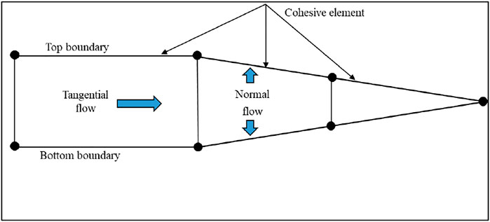
FIGURE 1. Fluid flow in the fracture.
Normal flow is related to the leak-off of fracturing fluid; this process is usually simplified by the leak-off coefficients. The simplified leak-off process is expressed as follows:
where
Tangential flow (Figure 1) has a significant influence on the effect of hydraulic fracturing, and the characteristics of the tangential flow in fractures are mainly determined by the fluid viscosity. The internal tangential flow is calculated by the parallel laminar flow formula. The flow rate is proportional to the cube of the fracture width, which is shown in the following equation:
where
Cohesive Zone Model
The cohesive zone model (CZM) was proposed (Dugdale, 1960; Barenblatt, 1962) to solve the problem of crack tip stress singularity in linear elastic fracture mechanics (LEFM) and was initially applied to metal materials. Hillerborg (1976) extended its application to quasi-brittle materials, and rock fracture can also be described by this model. In the CZM, the bilinear traction-separation law is a traditional model for simulating the damage and failure process of rock (Chen et al., 2009). As shown in Figure 2, the horizontal axis
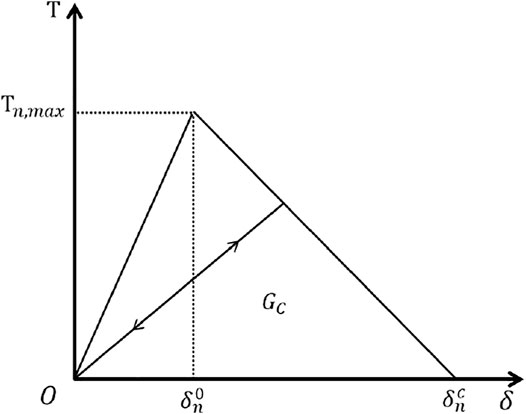
FIGURE 2. Bilinear traction-separation law of the cohesive element.
In the numerical model, the maximum nominal stress traction-separation law is applied to judge the initiation of damage, as shown in the following formula:
where
If
Once the critical point of the damage is reached, the rock shows softening performance. To determine the damage degree of the rock, damage factor D is defined, which is related to
where D is the damage factor, and when D = 1, rock completely fails and macroscopic fracture appears.
Global Cohesive Zone Model
The cohesive element requires a predetermined fracture propagation path, and the traditional CZM is usually employed to simulate the crack propagation process with a known path. However, in the hydraulic fracturing process, the direction of the fracture propagation is determined by many factors, resulting in the uncertainty of the fracture extension direction. To overcome the deficiency of the traditional CZM and enrich the propagation path of the fracture, a method of the global cohesive zone model is established by the global embedding of zero-thickness cohesive elements. This work is realized by the secondary development of ABAQUS software. The propagation path of fractures can be regarded as arbitrary, and the GCZM is employed to simulate the propagation process of the complex fracture networks.
Several key issues should be addressed in GCZMs. First, to ensure continuous fracture propagation and continuous fluid flow, the pore pressure of the adjacent coincidence nodes should be equal. Hence, all adjacent cohesive elements are designed to share one seepage node (Figure 3), simplifying the complicated process. The direction of the cohesive element is also an important problem. When the cohesive elements are inserted globally, a cross-product of the vector is used to determine the normal direction of each cohesive element, as well as the embedding direction of the cohesive element and the order of the corresponding nodes (shown in Figure 4). In the model, the direction of the cohesive element should be noted; otherwise, penetration of the rock element may occur.
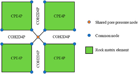
FIGURE 3. Schematic diagram of cohesive elements sharing one seepage node.
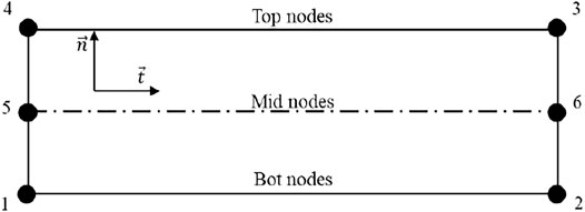
FIGURE 4. Diagram of the normal direction of the cohesive element.
Reservoir Hydraulic Fracturing Model Implementation
Model Overview
In this study, a two-dimensional (2D) hydraulic fracturing model was established in the finite element software ABAQUS. A Python program was developed to embed a group of natural fractures into the reservoir model according to a fracture density parameter (Figure 5A).
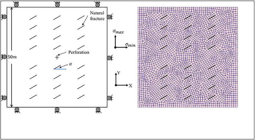
FIGURE 5. (A) Schematic diagram of reservoir model and boundary condition. (B) Reservoir finite element model and natural fracture embedding diagram.
To simulate fracture propagation in an actual reservoir with a planar model, several assumptions are needed. 1) The rock is treated as a linear elastic material; 2) the fracturing fluid is assumed to be Newtonian fluid and incompressible; 3) the fluid flow in the pores conforms to Darcy’s law, and the fracture fluid obeys the cubic law. The size of the reservoir model was 50 m × 50 m, and 24 natural fractures were embedded in the model (Figure 5A). These natural fractures were designed as a fracture group with the same dip angle and cement strength. The perforation is located in the middle of the model, which is represented by two cross lines. Note that the length of each cohesive element at the fracture initiation point was set equally to avoid the calculation error caused by the element length.
Figure 5B shows the meshing of the reservoir finite element model. The mesh size was 1 m, and the number of elements was 7,602–7,857 due to the difference in meshing caused by various NF dip angles. As shown in Figure 3, a 4-node CPE4P element that supports seepage calculation is performed to simulate the rock matrix, and a 6-node COH2D4P cohesive element, including a fluid-mechanic coupling calculation, is utilized for fracture simulation. To improve the convergence of the numerical simulation, the damping parameter of the COH2D4P element is set to 0.01. In the fluid-mechanic coupling simulation, the mid nodes (5 and 6 in Figure 4) of COH2D4P are applied to simulate the fluid flow in the fracture, which enables the element to simulate the process of hydraulic fracture propagation. In Figure 5B, the locations of natural fracture elements are highlighted with bold black lines to distinguish the mesh lines near the natural fractures.
Boundary Conditions and Initial Conditions
Figure 5A shows the displacement boundary conditions of the reservoir model. The left and right boundaries impose displacement constraints in the X direction, while the upper and lower boundaries impose displacement constraints in the Y direction. In addition, the pore pressure of the four boundaries is set to 0.1 MPa.
As shown in Figure 5A, fluid is injected into the reservoir from the point located at the central cross point of the model. To enhance the convergence performance of the numerical simulation, the flow rate gradually increases until it reaches the preset value instead of setting the maximum value directly at the beginning of the simulation.
Hydraulic fracturing numerical simulation is divided into two stages: the initial stage and the hydraulic fracturing stage. In the first stage, the initial condition parameters of the reservoir, such as the initial in situ stress, initial porosity, and initial pore pressure, are given to obtain the initial state of the reservoir. The initial in situ stress is an important parameter of hydraulic fracturing simulation, which affects the complexity of the fracture network. The initial porosity and initial pore pressure are set to 0.1 and 0.1 MPa. Under the initial conditions and boundary conditions, a static state is obtained.
After the completion of the initiation stage, the hydraulic fracturing stage is simulated by injecting the fluid into the reservoir, which is computed with the transient method.
Results and Discussion
In shale reservoirs with natural fractures, the propagation of the hydraulic fracture network is a very complicated process that is affected by many factors. These include the in situ stress difference, the approach angle and cement strength of the natural fractures, injection rate, and fracturing fluid viscosity. Generally, the first three factors are geological factors, and the other two factors are operation parameters. To discuss the effect of the factors on the reservoir stimulation after fluid injection for 20 s, several cases are designed in Table 1.
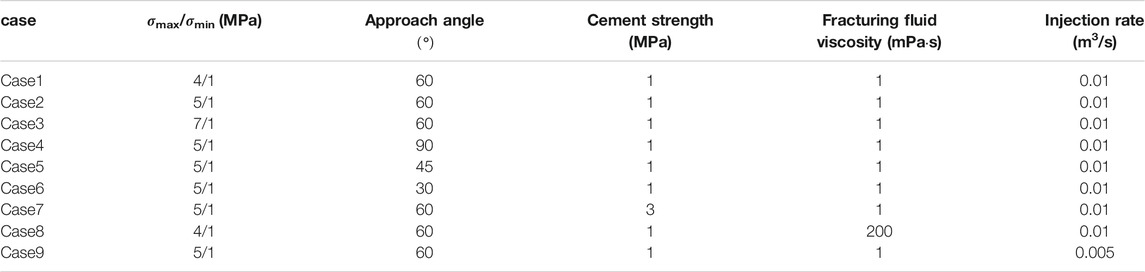
TABLE 1. Hydraulic fracturing parameters used in different cases.
In the numerical simulation, other basic properties of the reservoir and fracturing fluid are listed in Table 2.
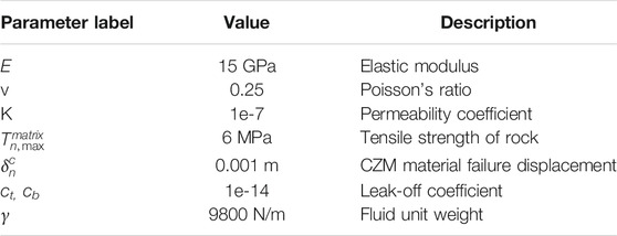
TABLE 2. Model constant parameters used in simulation.
Influence of the In Situ Stress Difference on the Fracture Network Propagation (Cases 1 ∼ 3)
In situ stress is one of the most significant factors affecting hydraulic fracturing performance (Shi et al., 2020). Hydraulic fractures always tend to develop along the maximum stress direction. When the in situ stress difference is high, the propagation direction of the hydraulic fracture is less disturbed by the other factors. To discuss the influence of the in situ stress difference (Δσ) on the propagation of the hydraulic fracture network, three values of Δσ are considered, namely, 2 MPa, 4 and 6 MPa. In these cases, the angle between HF and σmin is 30°, which can be classified as a low-angle NF. The simulation results obtained after fluid injection for 20 s, are shown in Figure 6.
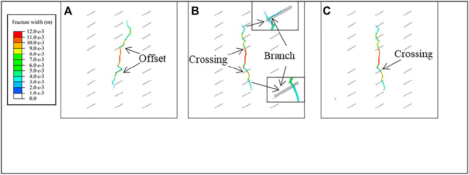
FIGURE 6. Morphology of hydraulic fracture network under Δσ: (A) 3 MPa in case 1; (B) 4 MPa in case 2; (C) 6 MPa in case 3.
In Figure 6, the grey solid lines represent the locations of the natural fractures. The colored belts represent the propagation path of the hydraulic fractures, and the widths of the hydraulic fractures are expressed by different colors. In terms of fracture morphology, the fracture under a low stress difference is more meandering, while the fracture is relatively straight and has a definite direction of propagation with a high Δσ. As shown in Figure 6A, when meeting the NF, the HF is more likely to divert to the direction of the NF and continue to propagate from the end of the NF. Although the NF is activated under the condition of a low Δσ, the narrow fracture width results in a relatively small stimulated area. With an increase in Δσ (4 MPa), the interaction between the HF and the NF is more complicated. For example, the HF crosses the NF and offsets the NF (Figure 6B). The NF is activated, and the stimulation area also increases, which is beneficial for improving the complexity of the fracture network and reservoir stimulation performance. When Δσ increases to 6 MPa (Figure 6C), the interaction between the HF and the NF appears as the crossing. The propagation direction of the hydraulic fracture is distinct. Although hydraulic fractures extend a long distance, NFs are not activated, which is not beneficial for forming a complicated fracture network.
Based on the simulation results, when the stress difference is very low, the fracturing area is relatively small in the reservoir containing natural fractures with low angles. The propagation direction of hydraulic fractures is easily affected by natural fractures, which tends to increase the complexity of the fracture network. On the other hand, when the stress difference is very high, the propagation direction of the hydraulic fracture is controlled by σmax. The hydraulic fractures are difficult to divert. The NFs cannot be activated, and few branch fractures are formed. The fracturing result shows a biwing planar fracture (Hou et al., 2019). When the stress difference is at a medium level, the interaction between the HF and the NF is more complicated. The division process can activate natural fractures and enhance the complexity of the fracture network. The crossing process favors an increase in the fracturing area. A large-scale, complex fracture network is achieved.
Influence of the Natural Fracture Approach Angle on Fracture Network Propagation (Cases 2, 4 ∼ 6)
Unlike other tight reservoirs, there are a large number of natural fractures in shale reservoirs. These fractures formed by tectonism and other geological reasons are the key factors affecting the effect of hydraulic fracturing. The density and dip angles of these fractures are often random to some extent. To control a single variable and study the influence of NF and HF approach angles on fracture network propagation, this article assumes that natural fractures in the reservoir are fracture groups with fixed density and equivalent angles. The approach angle indicates the angle between the maximum stress direction and the NF. In this article, if the dip angle of a natural fracture is
Since the approach angle has a significant effect on the stress field near the natural fractures, the approach angle is also an important parameter to simulate fracture network propagation. In this article, four simulation conditions of approach angles (

FIGURE 7. Morphology of hydraulic fracture network under different approach angles: (A)
Figure 7A shows that the hydraulic fractures and natural fractures are orthogonal. In this case, it is difficult for HFs to activate NFs and to obtain branch fractures, and the reservoir stimulation effect is poor. Figure 7B and Figure 7C show that when the approach angle is
According to the above-mentioned discussion, there is no simple positive or negative correlation between the approach angle and the fracturing effect. If the approach angle is too large, it is difficult to activate natural fractures, and if the approach angle is too small, it is difficult to generate branching fractures and complex fracture networks.
Influence of Natural Fracture Cement Strength on Fracture Network Propagation
Natural fractures in shale reservoirs are mostly filled with minerals such as calcite, which have tensile strength and are known as cemented fractures. To study the influence of the cement strength of the cemented fracture on the hydraulic fracturing effect, two groups of cemented strength conditions were established in this article: 1 and 3 MPa. The influence of NF cement strength on fracture network propagation is shown in Figure 8.
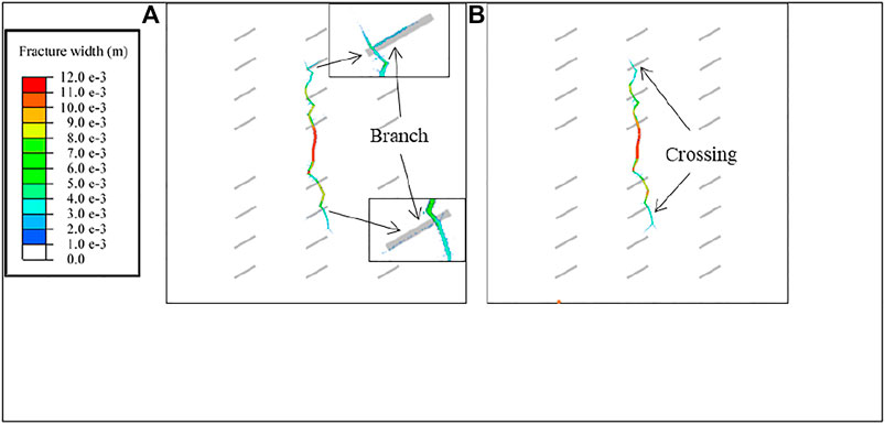
FIGURE 8. Morphology of hydraulic fracture network under different cement strengths: (A) case 2; (B) case 7.
Figure 8A shows that if the natural fracture has a cement strength of 1 MPa when the hydraulic fracture propagates near the natural fracture, the fracture is divided into two branches: the first branch passes directly through the natural fracture, and the second branch is offset along the natural fracture and expands independently. Figure 8B shows that when the natural fracture cement strength is 3 MPa, the HF does not branch but directly passes through the natural fracture without increasing the complexity of the fracture network.
In conclusion, when natural fractures are filled with minerals and have high strength, hydraulic fractures do not easily activate natural fractures; it is difficult to form a complex fracture network; and the reconstruction effect cannot reach the optimal level. In contrast, when the cement strength of natural fractures is low, hydraulic fractures are more likely to propagate or offset along natural fractures, resulting in more complex fracture networks and enhanced fracturing and stimulation effects.
Influence of Fracturing Fluid Viscosity on Fracture Network Propagation
Horizontal in situ stress differences, natural fracture approach angles, and cement strength are properties of the reservoir itself that engineers can only adapt to but cannot change. However, fracturing fluid viscosity and injection rate differ, which are two of the most important operation parameters that can be adjusted flexibly according to reservoir properties. Two of the most widely employed fracturing fluids are guar fluid, which has a high viscosity that exceeds
Fracturing fluids with different viscosities have a wide range of effects. Engineers and numerous experiments have revealed that high-viscosity fracturing fluid forms long, straight fractures, while low-viscosity fracturing fluid forms tortuous fractures near the wellbore. The effect of fracturing fluid viscosity on the interaction between hydraulic fractures and natural fractures is not as significant as that of the in situ stress difference. Generally, only when the viscosity of the fracturing fluid is different by order of magnitude can the difference in fracture network morphology be observed. In this article, two different conditions of fracturing fluid viscosity are established for comparison. The first condition is simulated guar gum liquid with a viscosity of
Figure 9A shows the fracture network propagation when the fracturing fluid viscosity is
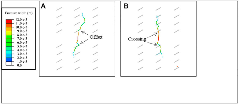
FIGURE 9. Morphology of hydraulic fracture network under different fluid viscosities: (A) case 1; (B) case 8.
Figure 9 shows that low viscosity fracturing fluid is more likely to form complex fracture networks, but the length of principal hydraulic fracture is shorter. Moreover, the influence of fracturing fluid viscosity on hydraulic fracturing can only be reflected when the viscosity is greatly different, so it is difficult to obtain the optimal solution of fracturing fluid viscosity. Fracturing fluids with different viscosities have different roles in hydraulic fracturing engineering, and fracturing fluids with different viscosities are commonly employed in different stages of construction in actual engineering. For example, in shale gas production operations in the Sichuan Basin, multiple fracturing fluids are often alternately utilized for multistage fracturing reservoir stimulation (Cao et al., 2020). Therefore, fracturing fluid can be flexibly changed in different fracturing stages according to engineering needs to obtain the best fracturing effect.
Influence of Injection Rate on Fracture Network Propagation
Similar to fracturing fluid viscosity, the fracturing fluid injection rate is an important operation parameter in shale gas exploitation. In engineering, a large injection rate is often used to rapidly break the reservoir and increase the width of the fracture at perforations to avoid sand plugging and other accidents. In this article, two injection rates are selected to study the influence of injection rates on the hydraulic fracture network propagation of the reservoir:
As shown in Figure 10A, when the injection rate is low, the length and width of hydraulic fractures are small, and the formed hydraulic fractures do not easily generate branch fractures. As shown in Figure 10B, the length and width of hydraulic fractures formed at a higher injection rate are significantly larger than those formed at a lower injection rate. In addition, as shown in Figure 10B, the higher the injection rate, the greater the stress at the hydraulic fracture front, and the higher the probability of hydraulic fracture branching, which makes it easier to generate complex fracture networks and improve the effect of reservoir stimulation.
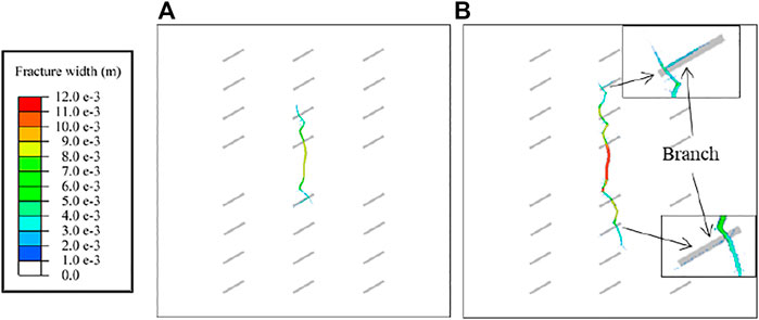
FIGURE 10. Morphology of hydraulic fracture network under different injection rates: (A)
If more fluid is injected at a higher rate, the fracture length will be longer at the same time. However, the effect of a high injection rate on hydraulic fracturing is not limited to length; it can effectively increase fracture width, improve hydraulic fracture conductivity, and reduce sand plugging risk. In practical engineering, especially hydraulic fracturing engineering with large-scale fracturing volume technology, the displacement of reservoir stimulation will be large enough to form fractures with better conductivity and improve the fracturing effect.
Figure 11 shows the variation in the bottomhole (BH) pressure curve with fracturing time during hydraulic fracturing. As shown in Figure 11, with an increase in injection rate, the net pressure in the fracture during fracture propagation also increases. The higher the net pressure is in the fractures, the easier it is to open the natural fractures in the reservoir and then to form a complex hydraulic fracture network (Duan et al., 2019).
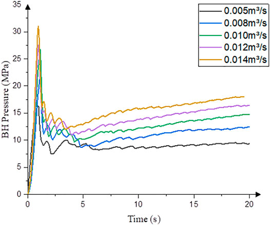
FIGURE 11. Bottomhole pressure-time history curve.
Figure 12 shows that as the injection rate increases, the bottomhole pressure at formation initiation increases. In addition, the higher injection pressure creates a wider principal fracture at the injection point, significantly increasing conductivity and reducing the risk of sand plugging.
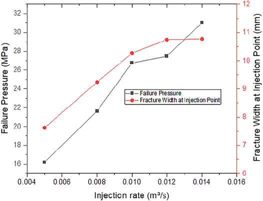
FIGURE 12. Failure pressure and fracture width at injection point for various injection rates.
According to the above-mentioned analysis, increasing the injection rate can increase the net pressure in the fracture, which can more easily activate natural fractures, thus forming a complex fracture network. For hydraulic fracturing operations, increasing the injection rate can increase the pump pressure, but it can also improve the fracture conductivity near the well and reduce the risk of sand plugging.
Conclusion
In this article, a two-dimensional, hydraulic fracturing, fluid-mechanic coupling, fracture propagation model was established to simulate the hydraulic fracture network propagation process of shale reservoirs with natural fractures. The influences of geological factors, such as the horizontal in situ stress difference, the approach angle of natural fractures, and cement strength on fracture network propagation, were investigated. In addition, the influence of operation parameters such as fracturing fluid viscosity and injection rate on hydraulic fracture network propagation was investigated, and a hydraulic fracturing optimization scheme is proposed. Through numerical simulation and results analysis, the following conclusions were obtained:
1) The results show that the greater the difference in ground stress, the less likely it is to form a complex fracture network, but the length of the main fracture will increase; when the approach angle is low, hydraulic fractures tend to shift along the natural fracture surface, increasing the complexity of the fracture network; when the cementation strength of natural cracks is high, the hydraulic fracture does not easily activate natural fractures. Using a low-viscosity fracturing fluid enables hydraulic fractures to activate natural fractures and form a fracture network; large-displacement fracturing can increase the widths of fractures and avoid sand plugging.
2) Reservoir geological conditions, such as the horizontal in situ stress difference, geometric distribution, and strength properties of natural fractures, are the main factors affecting the expansion of hydraulic fracture networks, which can only be fully utilized (e.g., multistage fracturing technology and large-scale fracturing technology) but have difficulty changing geological conditions. To fully utilize the reservoir geological conditions, it is necessary to accurately measure the in situ stress before drilling, obtain reservoir microseismic data, and determine the distribution and density of natural fractures in reservoirs with geological exploration data.
3) Operation parameters, such as fracturing fluid viscosity and injection rate, are important parameters that can be mastered by engineers and have a significant influence on the reservoir stimulation effect. As high-viscosity fracturing fluids and low-viscosity fracturing fluids have distinct advantages and disadvantages, different-viscosity fracturing fluids can be employed in the operation of alternating fracturing fluid injection.
4) The injection rate, often referred to as the displacement rate in operation, has a significant effect on fracture network propagation and near-wellbore fractures. Increasing the injection rate can increase the net pressure in the fracture and form a complex fracture network. On the other hand, higher injection rates can increase the widths of near-wellbore fractures, significantly reducing the risk of sand blockage and other accidents. Therefore, the injection rate should be increased in hydraulic fracturing operations to achieve the best reservoir stimulation effect.
Data Availability Statement
The raw data supporting the conclusions of this article will be made available by the authors, without undue reservation.
Author Contributions
YY and ZJ were responsible for the conceptualization, modeling, and writing. LD contributed to the discussion and suggestions for data analysis. HF acquired the resources. All authors have read and agreed to the published version of the manuscript.
Funding
This study is financially supported by the National Natural Science Foundation of China (No. 51704197).
Conflict of Interest
HF was employed by Lingchuang Green House Construction Technology Co., Ltd.
The remaining authors declare that the research was conducted in the absence of any commercial or financial relationships that could be construed as a potential conflict of interest.
Publisher’s Note
All claims expressed in this article are solely those of the authors and do not necessarily represent those of their affiliated organizations, or those of the publisher, the editors, and the reviewers. Any product that may be evaluated in this article, or claim that may be made by its manufacturer, is not guaranteed or endorsed by the publisher.
References
Barenblatt, G. I. (1962). The Mathematical Theory of Equilibrium Cracks in Brittle Fracture. Adv. Appl. Mech. 7, 55–129. doi:10.1016/S0065-2156(08)70121-2
Blanton, T. L. “An Experimental Study of Interaction between Hydraulically Induced and Pre-existing Fractures,” in Proceedings of the SPE Unconventional Gas Recovery Symposium, Pittsburgh, Pennsylvania, May 1982. doi:10.2118/10847-MS
Cao, X., Wang, M., Kang, J., Wang, S., and Liang, Y. (2020). Fracturing Technologies of Deep Shale Gas Horizontal wells in the Weirong Block, Southern Sichuan Basin. Nat. Gas Industry B 7 (1), 64–70. doi:10.1016/j.ngib.2019.07.003
Chen, Z., Bunger, A. P., Zhang, X., and Jeffrey, R. G. (2009). Cohesive Zone Finite Element-Based Modeling of Hydraulic Fractures. Acta Mechanica Solida Sinica 22, 443–452. doi:10.1016/S0894-9166(09)60295-0
Cheng, L., Li, D., Wang, W., and Liu, J. (2021). Heterogeneous Transport of Free CH4 and Free CO2 in Dual-Porosity Media Controlled by Anisotropic In Situ Stress during Shale Gas Production by CO2 Flooding: Implications for CO2 Geological Storage and Utilization. ACS Omega 6 (40), 26756–26765. doi:10.1021/acsomega.1c04220
Chuprakov, D., Melchaeva, O., and Prioul, R. (2014). Injection-Sensitive Mechanics of Hydraulic Fracture Interaction with Discontinuities. Rock Mech. Rock Eng. 47 (5), 1625–1640. doi:10.1007/s00603-014-0596-7
Daneshy, A. “Hydraulic Fracture Propagation in the Presence of Planes of Weakness,” Paper SPE-4852-MS in Proceedings of the SPE European Spring Meeting, May 1974 (Amsterdam, Netherlands. doi:10.2118/4852-ms
Duan, H., Li, H., Dai, J., Wang, Y., and Chen, S. A. (2019). Horizontal Well Fracturing Mode of "increasing Net Pressure, Promoting Network Fracture and Keeping Conductivity" for the Stimulation of Deep Shale Gas Reservoirs: A Case Study of the Dingshan Area in SE Sichuan Basin. Nat. Gas Ind. B 6 (5), 497–501. doi:10.1016/j.ngib.2019.02.005
Dugdale, D. S. (1960). Yielding of Steel Sheets Containing Slits. J. Mech. Phys. Sol. 8, 100–104. doi:10.1016/0022-5096(60)90013-2
Feng, Q., Xu, S., Xing, X., Zhang, W., and Wang, S. (2020). Advances and Challenges in Shale Oil Development: A Critical Review. Adv. Geo-energy Res. 4, 406–418. doi:10.46690/ager.2020.04.06
Gale, J., Laubach, S., Olson, J., Eichhubl, P., and Fall, A. (2014). Natural Fractures in Shale: A Review and New Observations. AAPG Bulletin 98, 2165–2216. doi:10.1306/08121413151
Gu, H., Weng, X., Lund, J., Mack, M., Ganguly, U., and Suarezrivera, R. (2012). Hydraulic Fracture Crossing Natural Fracture at Nonorthogonal Angles: A Criterion and its Validation. SPE Prod. Oper. 27 (1), 20–26. doi:10.2118/139984-pa
Guo, J., Zhao, X., Zhu, H., Zhang, X., and Pan, R. (2015). Numerical Simulation of Interaction of Hydraulic Fracture and Natural Fracture Based on the Cohesive Zone Finite Element Method. J. Nat. Gas Sci. Eng. 25, 180–188. doi:10.1016/j.jngse.2015.05.008
Hillerborg, A., Modéer, M., and Petersson, P.-E. (1976). Analysis of Crack Formation and Crack Growth in concrete by Means of Fracture Mechanics and Finite Elements. Cement Concrete Res. 6 (6), 773–781. doi:10.1016/0008-8846(76)90007-7
Hou, B., Chang, Z., Fu, W., Muhadasi, Y., and Chen, M. (2019). Fracture Initiation and Propagation in a Deep Shale Gas Reservoir Subject to an Alternating-Fluid-Injection Hydraulic-Fracturing Treatment. SPE J. 24 (04), 1839–1855. doi:10.2118/195571-PA
Li, Y., and Bahrani, N. (2021). A Continuum Grain-Based Model for Intact and Granulated Wombeyan marble. Comput. Geotechnics 129, 103872. doi:10.1016/j.compgeo.2020.103872
Li, Y., Deng, J. G., Liu, W., and Feng, Y. (2017). Modeling Hydraulic Fracture Propagation Using Cohesive Zone Model Equipped with Frictional Contact Capability. Comput. Geotechnics 91, 58–70. doi:10.1016/j.compgeo.2017.07.001
Lin, T., Liu, X., Zhang, J., Bai, Y., Liu, J., Zhang, Y., et al. (2021). Characterization of Multi-Component and Multi-phase Fluids in the Upper Cretaceous Oil Shale from the Songliao basin (NE China) Using T1-T2 NMR Correlation Maps. Pet. Sci. Technol., 1–11. doi:10.1080/10916466.2021.1990318
Liu, R., Jiang, D., Zheng, J., Hao, F., Jing, C., Liu, H., et al. (2021a). Stress Heterogeneity in the Changning Shale-Gas Field, Southern Sichuan Basin: Implications for a Hydraulic Fracturing Strategy. Mar. Pet. Geology. 132, 105218. doi:10.1016/j.marpetgeo.2021.105218
Liu, R., Wen, T., Amalberti, J., Zheng, J., Hao, F., and Jiang, D. (2021b). The Dichotomy in noble Gas Signatures Linked to Tectonic Deformation in Wufeng-Longmaxi Shale, Sichuan Basin. Chem. Geology. 581, 120412. doi:10.1016/j.chemgeo.2021.120412
Liu, R., Zheng, J., Hao, F., Nie, Z., Heng, D., Tan, X., et al. (2020). Variation in Pore Systems with Tectonic Stress in the Overthrust Wufeng-Longmaxi Shale of the Southern Sichuan Basin, China. J. Nat. Gas Sci. Eng. 83, 103617. doi:10.1016/j.jngse.2020.103617
Liu, Y., Tang, D., Xu, H., Li, S., and Tao, S. (2018). The Impact of Coal Macrolithotype on Hydraulic Fracture Initiation and Propagation in Coal Seams. J. Nat. Gas Sci. Eng. 56, 299–314. doi:10.1016/j.jngse.2018.06.013
Ma, G., Li, M., Wang, H., and Chen, Y. (2020). Equivalent Discrete Fracture Network Method for Numerical Estimation of Deformability in Complexly Fractured Rock Masses. Eng. Geology. 277, 105784. doi:10.1016/j.enggeo.2020.105784
Maulianda, B., Savitri, C. D., Prakasan, A., Atdayev, E., Yan, T. W., Yong, Y. K., et al. (2020). Recent Comprehensive Review for Extended Finite Element Method (XFEM) Based on Hydraulic Fracturing Models for Unconventional Hydrocarbon Reservoirs. J. Petrol. Explor Prod. Technol. 10 (8), 3319–3331. doi:10.1007/s13202-020-00919-z
Mayerhofer, M. J. J., Lolon, E. P. P., Warpinski, N. R. R., Cipolla, C. L. L., Walser, D., and Rightmire, C. M. M. (2010). What Is Stimulated Reservoir Volume? SPE Prod. Oper. 25, 89–98. doi:10.2118/119890-PA
Renshaw, C. E., and Pollard, D. D. (1995). An Experimentally Verified Criterion for Propagation across Unbounded Frictional Interfaces in Brittle, Linear Elastic Materials. Int. J. Rock Mech. Mining Sci. Geomechanics Abstr. 32 (3), 237–249. doi:10.1016/0148-9062(94)00037-4
Rueda Cordero, J., Sanchez, C., Roehl, D., and Pereira, L. (2019). Hydro-mechanical Modeling of Hydraulic Fracture Propagation and its Interactions with Frictional Natural Fractures. Comput. Geotech. 111, 300. doi:10.1016/j.compgeo.2019.03.020
Shi, S., Liu, Z., Feng, J., Feng, G., and Li, M. (2020). Using 3D Seismic Exploration to Detect Ground Fissure. Adv. Geo-energy Res. 4, 13–19. doi:10.26804/ager.2020.01.02
Sun, C., Zheng, H., Liu, W. D., and Lu, W. (2020). Numerical Simulation Analysis of Vertical Propagation of Hydraulic Fracture in Bedding Plane. Eng. Fracture Mech. 232, 107056. doi:10.1016/j.engfracmech.2020.107056
Wang, H. (2019). Hydraulic Fracture Propagation in Naturally Fractured Reservoirs: Complex Fracture or Fracture Networks. J. Nat. Gas Sci. Eng. 68, 102911. doi:10.1016/j.jngse.2019.102911
Wang, W., Zheng, D., Sheng, G., Zhang, Q., and Su, Y. (2017). A Review of Stimulated Reservoir Volume Characterization for Multiple Fractured Horizontal Well in Unconventional Reservoirs. Adv. Geo-energy Res. 1, 54–63. doi:10.26804/ager.2017.01.05
Warpinski, N. R., and Teufel, L. W. (1987). Influence of Geologic Discontinuities on Hydraulic Fracture Propagation (Includes Associated Papers 17011 and 17074 ). J. Petrol. Technol. 39, 209–220. doi:10.2118/13224-PA
Weng, X. (2015). Modeling of Complex Hydraulic Fractures in Naturally Fractured Formation. J. Unconventional Oil Gas Resour. 9, 114–135. doi:10.1016/j.juogr.2014.07.001
Yoon, J. S., Zang, A., Stephansson, O., Hofmann, H., and Zimmermann, G. (2017). Discrete Element Modelling of Hydraulic Fracture Propagation and Dynamic Interaction with Natural Fractures in Hard Rock. Proced. Eng. 191, 1023–1031. doi:10.1016/j.proeng.2017.05.275
Zhai, L., Zhang, H., Pan, D., Zhu, Y., Zhu, J., Zhang, Y., et al. (2020). Optimisation of Hydraulic Fracturing Parameters Based on Cohesive Zone Method in Oil Shale Reservoir with Random Distribution of Weak Planes. J. Nat. Gas Sci. Eng. 75, 103130. doi:10.1016/j.jngse.2019.103130
Zhao, H., Wu, K., Huang, Z., Xu, Z., Shi, H., and Wang, H. (2021). Numerical Model of CO2 Fracturing in Naturally Fractured Reservoirs. Eng. Fracture Mech. 244, 107548. doi:10.1016/j.engfracmech.2021.107548
Zhao, P., Xie, L., Ge, Q., Zhang, Y., Liu, J., and He, B. (2020). Numerical Study of the Effect of Natural Fractures on Shale Hydraulic Fracturing Based on the Continuum Approach. J. Pet. Sci. Eng. 189, 107038. doi:10.1016/j.petrol.2020.107038
Zheng, H., Pu, C., and Il, C. T. (2019). Study on the Interaction Mechanism of Hydraulic Fracture and Natural Fracture in Shale Formation. Energies 12, 4477. doi:10.3390/en12234477
Zheng, H., Pu, C., and Sun, C. (2020). Study on the Interaction between Hydraulic Fracture and Natural Fracture Based on Extended Finite Element Method. Eng. Fracture Mech. 230, 106981. doi:10.1016/j.engfracmech.2020.106981
Keywords: fluid-driven fracture, fracture network morphology, global cohesive zone method, numerical study, fracture properties
Citation: Yang Y, Jiao Z, Du L and Fan H (2021) Numerical Simulation of Shale Reservoir Fluid-Driven Fracture Network Morphology Based on Global CZM. Front. Earth Sci. 9:775446. doi: 10.3389/feart.2021.775446
Received: 14 September 2021; Accepted: 18 October 2021;
Published: 15 November 2021.
Edited by:
Gang Lei, King Fahd University of Petroleum and Minerals, Saudi ArabiaCopyright © 2021 Yang, Jiao, Du and Fan. This is an open-access article distributed under the terms of the Creative Commons Attribution License (CC BY). The use, distribution or reproduction in other forums is permitted, provided the original author(s) and the copyright owner(s) are credited and that the original publication in this journal is cited, in accordance with accepted academic practice. No use, distribution or reproduction is permitted which does not comply with these terms.
*Correspondence: Longhuan Du, bG9uZ2h1YW5fZHVAMTYzLmNvbQ==