- 1State Key Laboratory of Geomechanics and Geotechnical Engineering, Institute of Rock and Soil Mechanics, Chinese Academy of Sciences, Wuhan, China
- 2University of Chinese Academy of Sciences, Beijing, China
- 3China Railway Middle Real Estate Co. LTD, Zhengzhou, China
- 4Shenyang University of Technology, Shenyang, China
Geotechnical hazards such as debris flows, rock falls in slopes, rock collapse, and rockburst in underground mining or caverns are tightly correlated to the mechanical behavior of natural rock mass stability. Strength and failure mode of the natural rock mass are governed by the presented fissures. In this paper, samples containing T-shaped fissures with different geometry were prepared by rock-like materials and tested under varying uniaxial cyclic loading compression. The effect of T-shaped fissures with different geometry and the strain rate and loading frequency on the strength of tested samples were studied, and the failure mode of the samples containing T-shaped cross fissures under different working conditions was observed. The results show that the function of the minor fissures was not completely negative, and the strength of T-shaped fissure samples containing a major fissure with different inclination angles presented a varying trend with the increasing included angle between the major and minor fissures. Moreover, the strength of the cracked samples increased with the increase of the strain rate and loading frequency, and the larger the included angles between the major and minor fissures, the more sensitive the T-shaped fissure sample was to the change of frequency, but without a noticeable linear correlation relationship between the strength of the sample and the included angles between the major and minor fissures. In addition, the existence of the minor fissures had a significant impact on the failure mode of the sample, and the failure mode of the samples containing T-shaped cross fissures of the same geometry under the uniaxial compression and the uniaxial cyclic load was equivalent.
Introduction
Geotechnical hazards indicate geological or environmental processes, phenomena, and conditions that are potentially dangerous or pose a level of threat to human life, health, and property, or to the environment. Geotechnical hazards such as debris flows, rock falls in slopes, rock collapse, and rockburst in underground mining or caverns are tightly correlated to the mechanical behavior of rock mass stability (e.g., Huang et al., 2020; Huang et al., 2021). A better understanding of the rock mass behavior will greatly reduce damages by geotechnical hazards. It is generally known that most rock masses in nature are composed of rocks containing different types of structural planes (e.g., He et al., 2019a; He et al., 2019b). The location and distribution of the internal fissures of jointed rock mass have an essential effect on the strength, deformation, and failure mode of the rock mass (e.g., Park and Bobet, 2009; Janeiro and Einstein, 2010; Huang D. et al., 2016; Cui et al., 2021). Since the last century, a number of investigations have been done by researchers on the mechanical properties and failure modes of jointed rock mass such as single fissure samples (e.g., Park and Bobet, 2010; Haeri et al., 2014; Liu et al., 2019) and multiple fissures samples (e.g., Wong and Einstein, 2009a; Huang Y.-H. et al., 2016; Wang et al., 2018). Meanwhile, some researchers have prepared rock-like samples by cement mortar or gypsum (e.g., Bobet and Einstein, 1998; Wang et al., 2018), other researchers cut the required fissures on real rock to get closer to the real rock mass (e.g., Ingraffea and Heuze, 1980; Huang et al., 1990; Liu et al., 2019).
The failure modes of gypsum and sandstone samples with prefabricated fissures were investigated (e.g., Bobet and Einstein (1998); Parkt and Bobet, 2010; Wong and Chau, 1998). Secondary cracks at the tip of the prefabricated fissure were observed by both of them. Wong and Chau. (1998) found that secondary cracks can be divided into quasi-coplanar secondary cracks and oblique secondary cracks. Petit and Barquins. (1998) and Haeri et al. (2014) investigated the failure modes of rock samples with a single fissure, and some basic laws on the initiation and propagation of prefabricated cracks were concluded. The following conclusion was obtained by Lajtai (e.g., Lajtai 1969; Lajtai 1974) based on the investigation on the failure mode of cracked rock mass under uniaxial compression: two types of cracks occurred in fractured rock mass under uniaxial compression, i.e., wing cracks caused by tension and secondary cracks brought out by shear. Wing cracks caused by tension were generated at the tip of the preformed fissure and extended to the direction of compressive stress rapidly after initiation. Secondary cracks generated by shear also initiated at the tip of the preformed fissure, the propagation direction of quasi-coplanar secondary cracks and oblique secondary cracks was opposite to that of the preformed fissure and wing crack, respectively. Braceet Bombolakis, (1963) and Hoek Bieniawski, (1965) conducted unconfined compression and biaxial compression tests on flat glass samples containing a single fissure, and the Griffith fracture mechanics theory was applied to explain the mechanism of crack initiation and propagation in single fissure samples.
In the natural world, there exists more than one fissure in the real jointed rock mass. Bobet and Einstein (1998) investigated the failure modes of samples containing two fissures under different confining pressures. The failure mode of the cracked sample is mainly affected by the confining pressure and geometric characteristics of two fissures inside the sample, and the generated location of the wing crack moves from the end of the prefabricated fissure to the middle of the prefabricated fissure as the confining pressure increases. The cracking characteristics of shear crack under different confining pressures were investigated by Bobet (2000), the result showed that the shear crack generated under high confining pressure could not cause destruction to the sample. Moreover, the effects of fissure geometry and materials on the cracking process of specimens were investigated, and nine crack coalescence categories with different crack types and trajectories were identified (e.g., Sagong and Bobet, 2002; Wong and Einstein, 2009a; Wong and Einstein, 2009b). It was found that although both tensile wing cracks and anti-wing cracks initiated at the tip of the prefabricated fissures, the propagation direction was opposite. Unconfined and biaxial compression tests on samples containing multiple fissures were conducted by Lin et al. (2000), the results showed that the failure mode and peak strength of the cracked sample were diverse due to the variation of the number and length of prefabricated fissures and the length of rock bridge and the size of lateral pressure, respectively. A comparative study on samples containing two and three fissures under uniaxial compression has been carried out by Tang et al. (2001). The comparison indicated that the cracking behavior of samples containing three fissures was analogous to that of samples with two fissures. Furthermore, the investigation on the failure mode of samples owning two and sixteen fissures (Sagong and Bobet 2002) showed that the failure mode of the sample containing multiple fissures was analogous to that of samples with two fissures under the same loading conditions, which further confirmed the conclusions of Lin et al. (2000).
Most joints and fissures with different lengths in the natural world are intersected with each other, whereas existing studies on this aspect remain rare. In this paper, T-shaped cracked samples containing different geometric fissures were prepared. The purpose of this work was to explore the effect of strain rate, loading frequency, and geometric characteristics of T-shaped fissures on the strength and failure mode of the samples, which can be applied as a guide in practical application of rock engineering.
Test Materials and Test Methods
Test Equipment
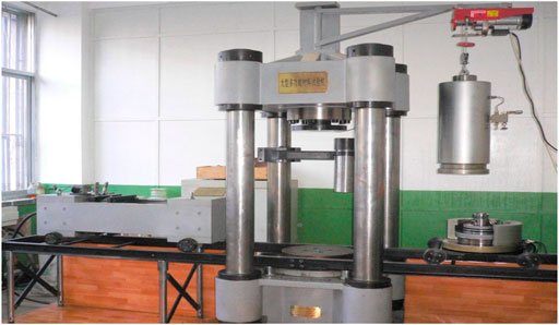
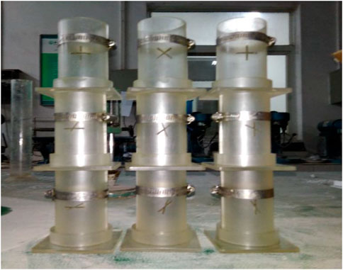
The test equipment used was the WDT-1500 Rock Test System (He et al., 2019; He et al., 2018) with a load capacity of 1,500 kN and frequency capacity of 10 Hz (see Figure 1). The test machine consists of five parts: an axial loading system, confining pressure loading system, transverse shearing system, acoustic wave detection system, and computer control and measurement system. The molds used in the test are shown in Figure 2.
Sample Preparation
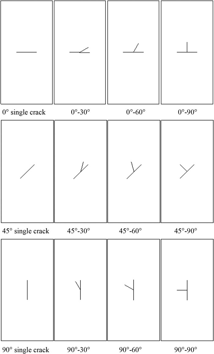
Uniaxial compressive tests (UCS) were carried out by Wang et al. (2018) to investigate the influence of prefabricated cracks with different geometric characteristic (various dip angles, lengths, widths, and numbers) on the mechanical properties and deformation failure modes of low-strength rock samples. The results showed that the mechanical properties of the cracked samples were primarily affected by the fissure dip angle, fissure number, and fissure length. The failure modes mainly involved the fissure dip angle and the fissure number. The dip angle of the prefabricated fissure was a key factor affecting the mechanical properties and failure mode of the samples under the same loading condition (Wang et al., 2018). In order to facilitate the analysis of the influence of the crossed cracks with different lengths and various inclination angles on the mechanical properties and failure mode of the samples, T-shaped was taken as the referent geometry, and the fissure geometry of the tested rock-like material sample is shown in Figure 3.
The crack geometry of the prefabricated fissures is described as follows: in order to distinguish the two fissures in the T-shaped cracked samples, the longer one was defined as the major fissure and the shorter one as the minor fissure, and the thickness of the major and minor fissures were taken at a constant of 0.3 mm. The fissure width of the single fissure samples with the inclination angle of 0°, 45°, and 90° to the horizontal was 20 mm. For the T-shaped cracked samples, the width of the major fissure was 20 mm, and the inclination angles to the horizontal was 0°, 45°, and 90°, respectively. The width of the minor fissure was 10 mm, and the included angles between the major and minor fissures were 30°, 60°, and 90°, respectively. Moreover, the prefabricated fissures were located in the middle of the specimens to minimize the influences of end friction on the tested sample.
In this paper, due to the homogeneity and the similar mechanical properties to natural rock, cement mortar material was chosen to prepare samples containing different geometrical fissures (e.g., Wasantha et al., 2012; Zhuang et al., 2014). It is easier to prefabricate open fissures in rock-like materials compared with natural rock. The mechanical behavior of the cement mortar material has been tested: its Poisson’s ratio is 0.27 and its deformation modulus is about 11.8 GPa.
The procedure for the fabricating the cracked samples is as follows:
1) We fabricated the cracked samples by compounding C32.5 cement, fine sand (the fineness modulus μf of sand is 1.8, and the particle size is less than 0.315 mm), and water at a mass ratio of 1.0:2.0:0.45 by weight.
2) Before pouring the mixed material, the mold was oiled and a copper sheet was added to facilitate the demoulding of the sample and the formation of the preformed fissures. It is easy to create open fissures by inserting a copper sheet with a thickness of 0.3 mm, certain rigidity, and stable property into the groove of the mold before pouring in the mixed materials, and pulling them out before complete solidification.
3) After being thoroughly blended, the homogeneous materials were poured into the fabricated mold (Figure 2). The mold was released after 24 h; hardened samples were placed in a curing box (20°C, humidity 90%) for 28 days, and then taken out to dry naturally. According to the method proposed by the International Society for Rock Mechanics, all kinds of cracked samples are cylinders with a diameter of 50 mm and a height of 100 mm.
4) Finally, both the two ends of the cracked samples were polished smoothly using a rock-grinding machine. The T-shaped cracked samples were named by two angles, one was the dip angle of the major fissure, the other was the included angle between the major and minor fissures. For example, a T-shaped fissure sample of 0°–90° means that the dip angle of the major fissure is 0° and the included angle between the major and minor fissures is 90°.
Test Methods
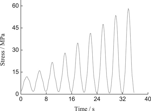
Two types of loading tests were conducted on each type of cracked sample, including uniaxial monotonic compression tests and multi-level single cyclic loading tests with different strain rates and frequency. The uniaxial monotonic compression tests adopted the loading mode of displacement control with a constant rate of 0.5 mm/min until the cracked samples were damaged. For the multi-level single cyclic loading tests (see Figure 4), at the beginning, the cracked samples were loaded to the upper limit of an initial cycle displacement of 0.2 mm, which was similar to the uniaxial monotonic compression tests, then the multi-level single cyclic loading tests were conducted. The loading waveform was the cosine waveform which has already been found to have a stronger dynamic effect than the triangle waveform (Bagde and Petros, 2005). Moreover, during the test, the lower limit of displacement was prescribed at 0.05 mm, and the upper limit of displacement was increased by 0.05 mm in each cycle which was greater than the former one until the test samples failed. Last but not least, to investigate the effect of strain rate on the strength and failure mode of the cracked samples, both the loading and unloading velocity of the platform were transferred by 0.05, 0.2, 0.5, and 1.0 mm/min (corresponding strain rate varied from 0.5*10–3 min−1 to 10–2 min−1) for applying cyclic loads. For the effect of loading frequency, cyclic loading was performed with the given frequencies of 0.05, 0.25, and 0.5 Hz separately (the corresponding cycle periods were 20, 4, and 2 s), because the period of each cycle at the same loading frequency was equal. This meant that the loading rate of the latter cycle was greater than that of the previous one by combining with the stress path of the cycle loading. As the loading frequency heightened, the corresponding loading rate of the latter cycle heightened. The specific experimental scheme can be presented in Table 1.

TABLE 1. Testing parameters of rock-like material specimens containing fissures of different geometric forms.
In order to distinguish the strength of the cracked samples under different working conditions, the strength under uniaxial monotonic compression was defined as static strength, and the strength under multi-level single cyclic loading tests was defined as dynamic strength.
Analysis of Test Results
In order to ensure the accuracy of the test results, three parallel tests were carried out on the cracked samples of the same type under the same experimental condition, and the test results were required to meet the following two criteria:
1) Under the same experimental conditions, the failure mode of the same type of the cracked sample is basically identical.
2) The stress-strain curve of the sample is similar, and the peak strength deviation is within 10%.
Besides, at least two samples can satisfy the criteria simultaneously, if necessary, additional test samples can be used for repeatability testing.
Strength Characteristics
Strength Characteristics Under Uniaxial Compression
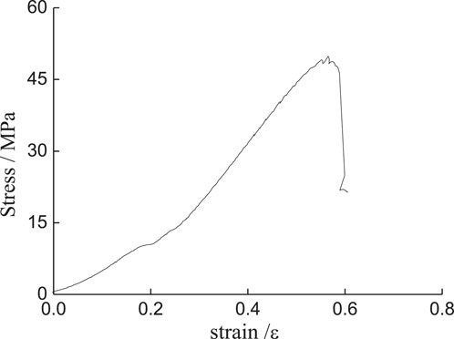
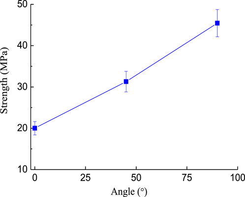
In this experiment, for a single fissure, the angle between the major and minor fissures was 0°, i.e., the minor fissure coincided with the major fissure, hence, the included angels between the major and minor fissures were 0°, 30°, 60°, and 90°, respectively. Figures 5, 6 show that the existence of fissures reduces the sample strength. The strength of the cracked samples was equivalent to 41.3–91.2% of the intact sample when the single fissure dip angle increased from 0° to 90°. The strength of the cracked samples increased with the increase of crack dip angles. This conclusion is consistent with the investigation by Qin et al. (2018) on the strength of rock-like samples containing a single fissure with different inclination angles.
From Figures 7B,C, at the major fissure dip angle of 45° and 90°, the existence of the minor fissures further reduced the strength of samples. Due to the increase of internal defects and the enhancement of fissure structure effect inside the samples caused by the minor fissures, the bearing capacity of the sample was mitigated (Wang et al., 2018). Moreover, with the increase of the included angle between the major and minor fissures, the strength of T-shaped fissure samples firstly decreased and then increased. However, the existence of the minor fissures enhanced the strength of the samples at the major fissure dip angle of 0° (see Figure 7A). Because the major fissure dip angle of 0° perpendicular to the direction of axial stress controls the failure of the sample (see Figures 12E–G) and destroys the integrity of the sample, the increase in strength of the cracked samples stems from the existence of the minor fissures which shares the stress field borne by the major fissure.
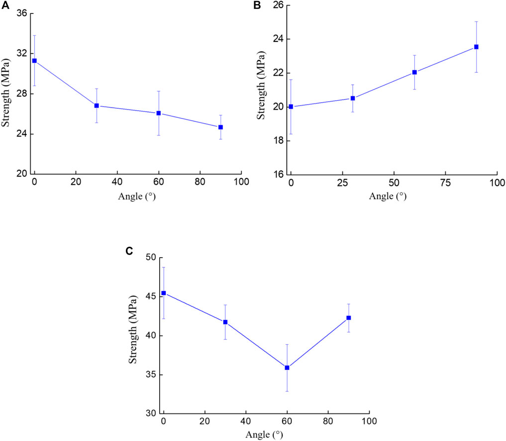
FIGURE 7. Relationship between the strength of all T-shaped cracked samples and the included angle between major and minor fissures. (A) T-shaped cracked sample containing the major fissure inclination angle of 0°, (B) T-shaped crack sample containing the major fissure inclination angle of 45°, (C) T-shaped crack sample containing the major fissure inclination angle of 90°.
From the above analysis, the existence of the minor fissures was soundly associated to the peak strength of the cracked sample, and the function of the minor fissures was not completely negative. Moreover, the strength of T-shaped fissure samples containing major fissures with different inclination angles had varying responses to the increasing included angle between the major and minor fissures.
Strength Characteristics Under Different Strain Rates
Figure 8 shows the effect of the strain rate on the strength of different types of cracked samples under cyclic loading. From Figure 8A, for the single fissure samples, when the strain rate increased from 0.05 mm/min to 1.00 mm/min, the 0° single fissure sample had the smallest strength increment of 2.18 MPa and the 90° single fissure sample corresponded to the largest strength increment of 8.52 MPa. Nevertheless, the strength increment of the cracked samples changed due to the existence of the minor fissure. In Figure 8B, for the major fissure inclination angle of 0°, the included angle between the major and minor fissures of 90° corresponded to the largest strength increment of 6.56 MPa. From Figures 8C,D, with the increase of the strain rate, the existence of the minor fissure had little influence on the strength increment at the major fissure inclination angle of 45°, for the major fissure inclination angle of 90°, the minor fissures reduced the strength increment of the cracked samples compared with the 90° single fissure sample. For the strain rate at the stage of 0.05 mm/min to 0.2 mm/min, the strength increment of 0°–30° and 45°–30° T-shaped cracked samples was larger, the strength increment subsequently tended to be stable with the continuous increase of the strain rate, indicating that the two samples were more sensitive to the strain rate at the stage 0.05 mm/min to 0.2 mm/min. This might be induced by the larger concentrated stress at the tip of the prefabricated fissures due to the smaller angle between the major and minor fissures. The effect of the concentrated stress was weakened with the increase of strain rate.
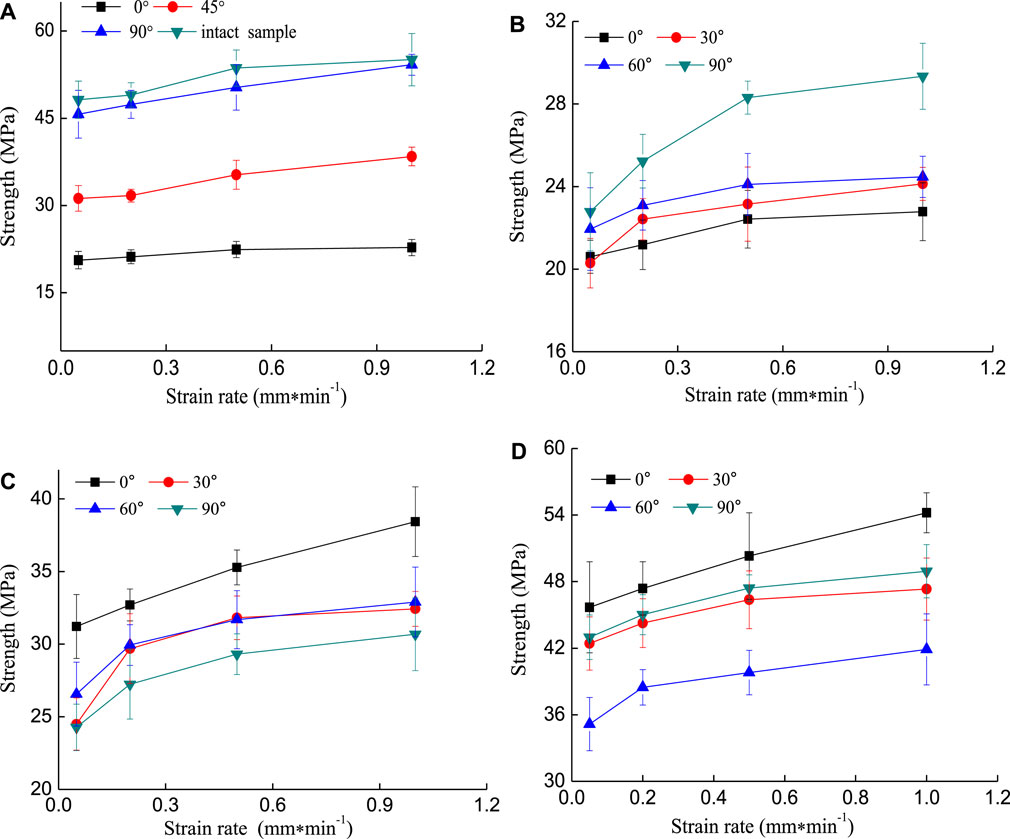
FIGURE 8. The relationship between the strength of cracked samples and strain rate. (A) Single crack samples with different inclination angles, (B) T-shaped crack samples containing the major fissure inclination angle of 0°, (C) T-shaped crack samples containing the major fissure inclination angle of 45°, (D) T-shaped crack samples containing the major fissure inclination angle of 90°.
From Figure 9, the ratio of dynamic strength to static strength increased with the increase of the strain rate. It is noted that the ratio of dynamic strength to static strength means the strength deterioration of the rock, depicting the mechanical characteristic of the rock with the dynamic load. Figure 9A shows that when the strain rate of cyclic loading was 0.05 mm/min, the dynamic strength of some samples was lower than its static strength, i.e., σs/σc < 1 (σs is the peak strength of the sample under cyclic loading, σc is the peak strength of the sample under uniaxial monotonic compression), such as the 45° single fissure samples. From Figures 9C,D, for the T-shaped fissure samples of 45°–30° and 90°–60°, although the existence of the minor fissures made their dynamic strength lower than their static strength at the strain rate of 0.05 mm/min, the growth rate of their dynamic strength was the largest and increased by 26.2 and 16.8% when the strain Figure 9A rate reached 1 mm/min, respectively. For the major fissure inclination angle of 0° (see Figure 9B), the existence of the minor fissures made their dynamic strength lower than their static strength at the strain rate of 0.05 mm/min. This is mainly due to the fact that the micro-cracks inside the sample have sufficient time for initiation and propagation when the strain rate is smaller and the damage of the sample is larger (Luo and Zhao, 2018). From the above analysis, the existence of the fissures with different geometries affected the strength Figure 9C increment of samples. The dynamic strength of the sample was sensitive to the change of the included angle between major and minor fissures without a noticeable linear correlation relationship.
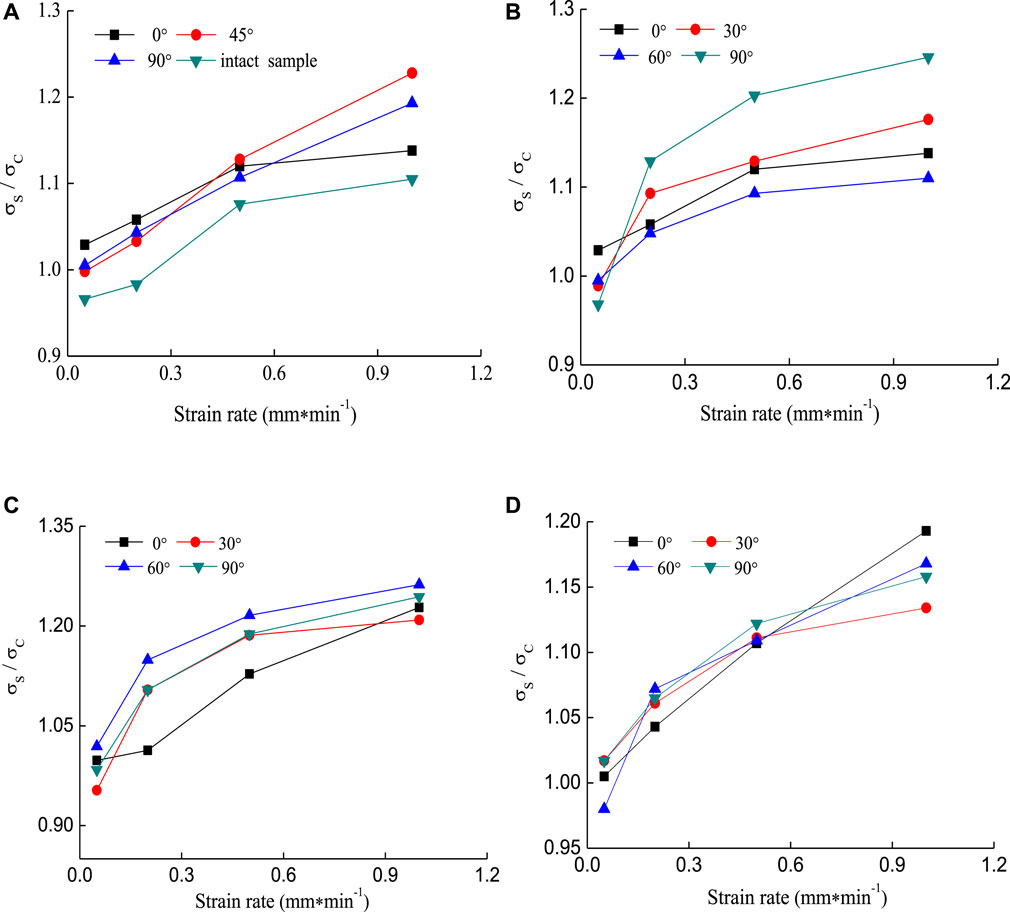
FIGURE 9. The relationship between the ratio of dynamic strength to static strength and the strain rate, (A) Single crack samples with different inclination angles, (B) T-shaped crack samples containing the major fissure inclination angle of 0°, (C) T-shaped crack samples containing the major fissure inclination angle of 45°, (D) T-shaped crack samples containing the major fissure inclination angle of 90°.
Strength Characteristics Under Different Frequencies
Figure 10 shows the effect of the frequency on the strength of samples with different geometrical fissures under cyclic loading. From Figure 10A, as the loading frequency increased, the existence of the single fissure with varying inclination inside the sample reduced the strength increment of the samples, especially for the 45° single fissure sample, the strength only increased by 3.45 MPa when the loading frequency increased from 0.05 to 0.5 Hz. For the T-shaped fissure samples, the existence of the minor fissures changed the response characteristics of the sample to frequency. As shown in Figures 10C,D, at the major fissure inclination angles of 0° and 90°, when the loading frequency increased from 0.05 to 0.5 Hz, the strength increment of the T-shaped fissure samples of 0°–90° and 90°–90° was the largest and increased by 6.1 and 11.93 MPa, respectively. This indicates that the two samples were more sensitive to the change of frequency due to the existence of the 90° minor fissure. For the major fissure inclination angle of 45° (see Figure 10C), as the loading frequency increased, the existence of the minor fissures enhanced the dynamic strength increment of samples compared with the 45° single crack sample. Thus it can be concluded that the dynamic strength of T-shaped crack samples containing a major fissure of 45° are more sensitive to cyclic loading compared with a 45° single fissure sample. From the above analysis, it is concluded that the dynamic strength of the T-shaped crack samples exhibits high frequency dependence. In addition, at the same stage of frequency ranging from 0.05 to 0.5 Hz, due to the existence of the fissures with different geometries inside the sample, with the increase of the frequency, different types of the cracked samples have different micro-crack densities, and the bite force between the particles and friction force on the shear surface are also varied, which lead to the different degrees of damage evolution in different types of the cracked samples (e.g., Li et al., 2001; Li et al., 2003). Therefore, the dynamic strength of samples depicts distinct characteristic with varying minor fissures.
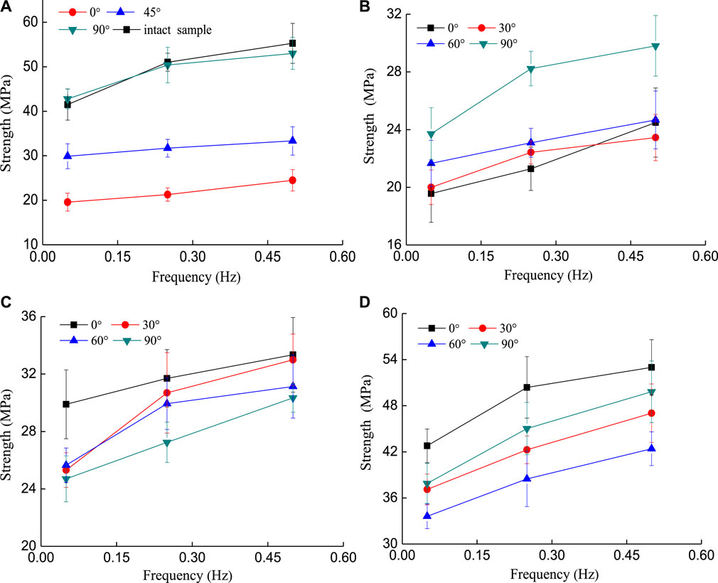
FIGURE 10. The relationship between strength of cracked samples and frequency. (A) Single crack samples with different inclination angles, (B) T-shaped crack samples containing the major fissure inclination angle of 0°, (C) T-shaped crack samples containing the major fissure inclination angle of 45°, (D) T-shaped crack samples containing the major fissure inclination angle of 90°.
The relationship between the ratio of dynamic strength to static strength and the loading frequencies is shown in Figure 11. With the increase of the frequency, the ratio of the dynamic and static strength of the samples raised. At the lower loading frequency of 0.05 Hz, the dynamic strength of all cracked samples were lower than their static strength, except for the T-shaped fissure samples of 0°–90° and 45°–90° (see Figures 11B,C). Because of the working condition of lower frequency and the cycle period is longer than the hysteresis time (e.g., Chen et al., 2004; Wan and Xi. 2009), the strain has sufficient reaction time. When the loading frequency reached 0.5 Hz, the dynamic strength growth ratio of the 0° single fissure sample was the largest and increased by 22.4% compared to its static strength (Figure 11A). For the T-shaped fissure samples with the major fissure of 0°, the growth rate of the dynamic strength was the largest when the angle between the major and minor fissures was 90° and increased by 26.6% compared to its static strength (Figure 11B). For the T-shaped fissure sample containing the major fissure of 90° (see Figure 11D), the growth rate of the dynamic strength was the largest when the included angle between the major and minor fissures was 60°, and its dynamic strength was increased by 18.2% compared to its static strength. From the above analysis, although the strength of the T-shaped crack sample increased as the frequency increased, it was found that the larger the included angles between the major and minor fissures, the more sensitive the T-shaped fissure sample was to the change of frequency. Therefore, rock masses containing larger included angles between the major and minor fissures under dynamic loading conditions should be paid more attention to.
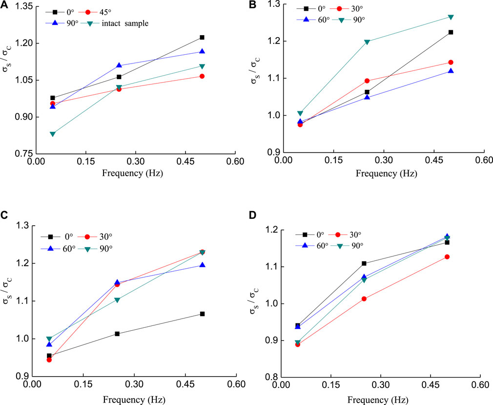
FIGURE 11. The relationship between the ratio of dynamic strength to static strength and the frequency, (A) single crack samples with different inclination, (B) T-shaped crack samples containing a primary crack inclination angle of 0°, (C) T-shaped crack samples containing a primary crack inclination angle of 45°, (D) T-shaped crack samples containing a primary crack inclination angle of 90°.
Failure Mode
Since the prefabricated cracks in this paper were penetration-type cracks, the cracking modes on both sides of the sample were basically the same, and the failure mode on one-side of the samples was selected for analysis.
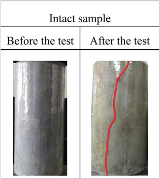
Figure 12 shows the failure mode of the intact sample. As shown in Figure 12, the tensile failure surface that formed by the upward and downward propagation of the tensile crack was generated in the middle of the sample. The crack extended to the upper part of the sample and propagated to the direction inclined to the compressive stress due to the hoop effect. When the direction of compressive stress was perpendicular or parallel to the pre-existing fissure, the tensile failure occurred, such as in the 0° single crack sample (Figure 13A) and 90° single crack sample (Figure 13B). Otherwise, shear-slip failure occurred, such as in the 45° single crack sample (Figure 13C). The failure of the 0° single fissure sample was mainly caused by the tension wing cracks generated at the left and right tip of the pre-existing fissure. The tension wing cracks expanded upward and downward to the top and bottom boundary of the test sample, respectively, showing significant tensile failure.
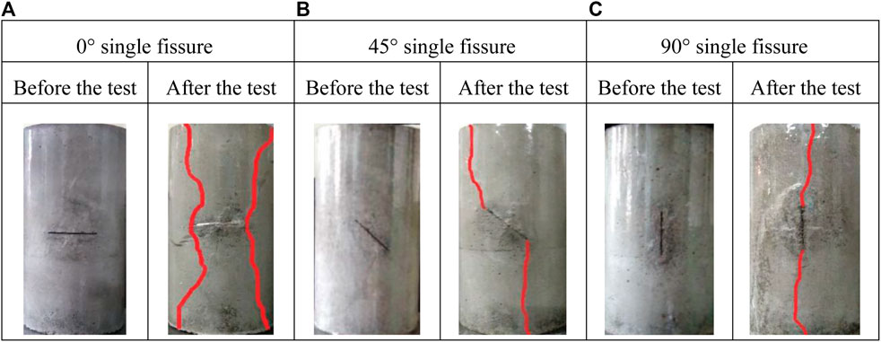
FIGURE 13. Failure mode of the cracked samples for (A) 0° single fissure sample, (B) 45° fissure crack sample, (C) 90° single fissure sample.
When the single fissure angle was 45°, firstly, a shear wing crack and tensile wing crack were initiated at the upper and lower tips of the pre-existing fissure and expanded upward and downward to the top and bottom boundary of the test sample, respectively. But then the shear wing crack stopped propagating after extending about 12 mm and turned into a tensile crack expanding to the sample boundary quickly. Finally, the samples slipped along the prefabricated crack surface when the axial compressive stress increased to the limit and exhibited the failure of tensile-shear composite. When the single fissure dip angle equaled 90°, in the initial stage, tensile cracks were initiated at the upper and lower tips of the pre-existing fissure, subsequently, the cracks gradually expanded upward and downward in the axial direction, respectively, and the sample was split into two vertical parts. The overall result was tensile failure, supplemented by shear failure in the lower part of the sample, and the samples failed as soon as the tensile cracks appeared.
Comparing Figure 13A and Figures 14A–C, the fracture modes of the T-shaped crack sample containing 0° major fissure were similar to that of the 0° single fissure sample: the propagation of the tension wing cracks were generated at one tip of the 0° major fissure, and all of them exhibited tensile failure. From Figure 14C, it can be seen that the failure mode of the T-shaped fissure sample of 0°–30° was rather special, coalescence occurred due to the propagation of the tensile crack initiating from the tip of the 0° major fissure toward the tip of the 30° minor fissure. This further confirms the result of Lee and Jeon (2011) who found that coalescence occurs mainly through tensile cracks. And tensile failure surface running through the sample usually appears on the side of the sample that the minor fissure lies in, however, due to the heterogeneity of rock-like materials, tensile failure surface running through the sample usually appears on one side of T-shaped fissure sample of 0°–90°. From the above analysis, at the dip angle of major fissure of 0°, the failure mode was controlled by the major fissure. With the increase of the included angle between the major and minor fissures, the effect of the minor fissure on the failure mode was gradually weakened.
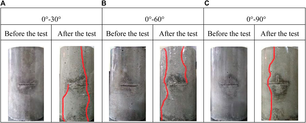
FIGURE 14. Failure mode of the cracked samples for (A) T-shaped cracked sample of 0°–30°, (B) T-shaped cracked sample of 0°–60°, (C) T-shaped cracked sample of 0°–90°.
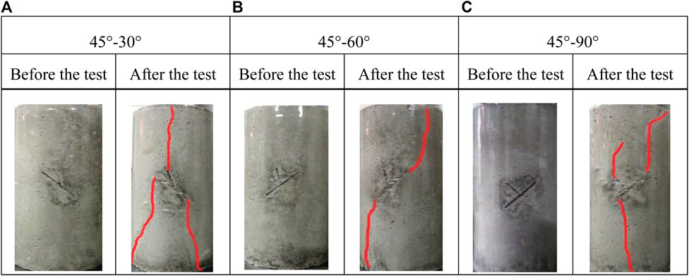
FIGURE 15. Failure mode of the cracked samples for (A) T-shaped cracked sample of 45°–30°, (B) T-shaped cracked sample of 45°–60°, (C) T-shaped cracked sample of 45°–90°.
When the major fissure dip angle was equal to 45° (see Figures 14A–C), the cracks slipped along the surface of the pre-existing fissure, which was mainly because of the small difference of the sample fissure inclination and internal friction under this condition. For the T-shaped fissure sample of 45°–90°, a tensile wing crack initiated at the minor fissure and a shear wing crack generated at the upper tip of the major fissure occurred simultaneously. However, the expansion speed of the crack at the tip of the major fissure was significantly faster than that at the tip of the minor fissure as the compressive stress increased. In addition, for the T-shaped fissure sample of 45°–60°, no crack sprouted at the end of the minor fissure. The existence of minor fissures with included angles of 60° and 90° to the major fissure had little effect on the fracture mode of samples. The failure mode of the two types of T-shaped fissure samples were similar to that of the 45° single fissure sample.
In Figure 14A, the existence of a 30° minor fissure had a significant effect on the failure mode of the sample. A tensile wing crack initiated at the minor fissure expanding upward to the top boundary of the sample, and the failure mode of the upper half of the sample was similar to that of the 90° single fissure sample. The tensile-shear composite crack and tensile crack that initiated at the upper and lower end of the major fissure expanded downward to the bottom boundary of the sample. The overall result was tensile failure, but locally shear failure occurred. At the dip angle of the major fissure of 45°, with the increase of the included angle between the major and minor fissures, the evolution of the failure mode of samples gradually changed from tensile failure to shear-slip failure.
Figures 16A–C show the failure mode of T-shaped fissure samples containing a 90° major fissure. For the T-shaped fissure samples of 90°–30° and 90°–60°, tensile wing cracks at the tip of pre-existing fissure propagated to the top and bottom of the sample, resulting in the destruction of the sample. At the initial stage, a shear wing crack was generated at the tip of the 30° and 60° minor fissures and propagated a short distance of about 2–3 mm, subsequently. Lee and Jeon (2011) studied the crack propagation on granite specimens under uniaxial compression, their results indicated that tensile cracks initiate from shear cracks, which is in good agreement with the findings in this paper.
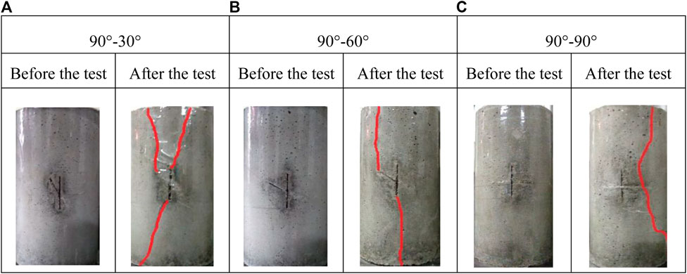
FIGURE 16. Failure mode of the cracked samples for (A) T-shaped cracked sample of 90°–30°, (B) T-shaped cracked sample of 90°–60°, (C) T-shaped cracked sample of 90°–90°.
From Figure 16C, the failure mode of the T-shaped fissure sample of 90°–90° was similar to that of the 0° single fissure sample. Although the length of the major fissure was twice that of the minor fissure, no cracks sprouted at the upper and lower tip of the major fissure. During the process of loading, tensile wing cracks that generated at the tip of the minor fissure expanded upward and downward to the top and the bottom boundary of the sample respectively, showing the failure of tensile significantly. Briefly speaking, at the dip angle of the major fissure of 90°, with the increase of the included angle between the major and minor fissures, the evolution of the failure mode of samples gradually changed from tensile failure to supplemented shear failure, and the effect of the minor fissure on the failure mode was gradually strengthened.
From Figures 12–16, some features of crack initiation and failure modes in pre-fissured samples can be summarized as follows. According to the classification of crack types (e.g., Sagong and Bobet, 2002; Wong and Einstein, 2009a; Wong and Einstein, 2009b), three cracks types are concluded in the present study, i.e., tensile wing crack, shear wing cracks, and anti-wing crack. Wing crack initiate at the tips of the pre-existing fissure and propagate towards the direction of compressive stress in a stable manner (e.g., Park and Bobet 2010; Cao et al., 2015), and tensile wing cracks initiate from shear cracks (Lee and Jeon 2011). Furthermore, the propagation direction of anti-wing cracks is opposite to that of wing cracks (Yang and Jing 2011). For the failure mode of the T-shaped fissure samples, for the inclined or horizontal major fissures, with the decrease of the included angle between the major and minor fissures, the effect of the minor fissure was gradually strengthened. But there was a special case, at the dip angle of the major fissure of 90° which was parallel to the direction of compressive stress, the effect of the minor fissure was strengthened with the increase of the included angle between the major and minor fissures, and the failure of the sample was controlled directly by the minor fissure at the included angle between the major and minor fissures of 90°. At last, by observing the failure mode of the fissure sample of the same type under different experimental conditions, it was found that the failure mode of the samples with the same fissure geometry was very similar. Due to the change of the test conditions and heterogeneity effect of the rock-like materials, there were some minor differences among them with the same fissure geometry, i.e., the failure mode of the samples containing prefabricated fissures under uniaxial monotonic compression and equivalent multi-level single cyclic loading.
Conclusion
In this paper, uniaxial monotonic compression tests and multi-level single cyclic loading tests with different strain rate and frequency were carried out for samples containing cracks with different geometry. The test results indicate that the existence of the minor fissures exerted apparent effects on the strength. The existence of the minor fissures also had an impact on the failure mode of the cracked samples significantly, even in some cracked samples, where the minor fissure controlled the failure of the samples.
The existence of the minor fissures was soundly associated with the peak strength of the cracked sample, and the function of the minor fissures was not negative overall. For the T-shaped fissure samples containing the major fissure inclination angle of 0°, the strength of the samples increased with the increase of the included angle between the major and minor fissures. At the major fissure inclination angle of 45° and 90°, with the increase of the angle between the major and minor fissures, the strength of T-shaped crack samples decreased first and then increased.
The strength of the cracked samples increased with the increase of the strain rate and loading frequency. Under cycle loading with different strain rates, the dynamic strength of the sample was sensitive to the included angle between major and minor fissures, but without a noticeable linear correlation relationship. Under cycle loading with different loading frequencies, if the angles between the major and minor fissures were larger, the strength of the T-shaped crack sample was more sensitive to the change of frequency.
The failure mode of the samples containing cracks of the same geometry under the uniaxial compression and the uniaxial cyclic load was equivalent. For the inclined or horizontal major fissure, the minor fissure had a significant effect on the failure mode of the sample, and the effect was strengthened with the decrease of the angle between the major and minor fissures. At the major fissure inclination angle of 90°, the effect of the minor fissures on the failure mode of the sample was strengthened with the increase of the angle between the major and minor fissures.
Finally, in order to deeply understand the characteristics of T-shaped cracked samples, strength of the samples with different fissure geometry at the same strain amplitude under multi-level single cyclic loading with different strain rate and frequency, and some other mechanical properties of the fissure samples will be investigated in the subsequent work.
Data Availability Statement
The raw data supporting the conclusions of this article will be made available by the authors, without undue reservation.
Author Contributions
LC put forward the general framework of the paper, was responsible for drafting the paper, and sorted and analyzed the follow-up data; YL mainly made important modifications to the paper and gave some key opinions; QS mainly sorted out the test materials and literature, participated in the test and drawing, and approved the final paper to be published; PX mainly participated in the process of the experiment and helped to draw.
Conflict of Interest
YL was employed by the company China Railway Middle Real Estate Co. LTD.
The remaining authors declare that the research was conducted in the absence of any commercial or financial relationships that could be construed as a potential conflict of interest.
Publisher’s Note
All claims expressed in this article are solely those of the authors and do not necessarily represent those of their affiliated organizations, or those of the publisher, the editors and the reviewers. Any product that may be evaluated in this article, or claim that may be made by its manufacturer, is not guaranteed or endorsed by the publisher.
Acknowledgments
The authors acknowledge the financial support provided by the National Science Foundation of China (Grant No. 52009129).
References
Bagde, M. N., and Petroš, V. (2005). Waveform Effect on Fatigue Properties of Intact sandstone in Uniaxial Cyclical Loading. Rock Mech. Rock Engng. 38, 169–196. doi:10.1007/s00603-005-0045-8
Bobet, A., and Einstein, H. H. (1998). Fracture Coalescence in Rock-type Materials under Uniaxial and Biaxial Compression. Int. J. Rock Mech. Mining Sci. 35, 863–888. doi:10.1016/s0148-9062(98)00005-9
Bobet, A. (2000). The Initiation of Secondary Cracks in Compression. Eng. Fracture Mech. 66, 187–219. doi:10.1016/s0013-7944(00)00009-6
Brace, W. F., and Bombolakis, E. G. (1963). A Note on Brittle Crack Growth in Compression. J. Geophys. Res. 68, 3709–3713. doi:10.1029/jz068i012p03709
Cao, P., Liu, T., Pu, C., and Lin, H. (2015). Crack Propagation and Coalescence of Brittle Rock-like Specimens with Pre-existing Cracks in Compression. Eng. Geology. 187, 113–121. doi:10.1016/j.enggeo.2014.12.010
Chen, Y.-P., Xi, D.-Y., and Xue, Y.-W. (2004). Attenuation and Hysteresis of Saturated Rocks under Cyclic Loading. Chin. J. Geophys. 47, 766–774. doi:10.1002/cjg2.3547
Cui, L., Sheng, Q., Dong, Y., Ruan, B., and Xu, D.-D. (2021). A Quantitative Analysis of the Effect of End Plate of Fully-Grouted Bolts on the Global Stability of Tunnel. Tunnelling Underground Space Tech. 114, 104010. doi:10.1016/j.tust.2021.104010
Haeri, H., Shahriar, K., Marji, M. F., and Moarefvand, P. (2014). Cracks Coalescence Mechanism and Cracks Propagation Paths in Rock-like Specimens Containing Pre-existing Random Cracks under Compression. J. Cent. South. Univ. 21, 2404–2414. doi:10.1007/s11771-014-2194-y
He, M., Huang, B., Zhu, C., Chen, Y., and Li, N. (2018). Energy Dissipation-Based Method for Fatigue Life Prediction of Rock Salt. Rock Mech. Rock Eng. 51, 1447–1455. doi:10.1007/s00603-018-1402-8
He, M., Li, N., Zhang, Z., Yao, X., Chen, Y., and Zhu, C. (2019a). An Empirical Method for Determining the Mechanical Properties of Jointed Rock Mass Using Drilling Energy. Int. J. Rock Mech. Mining Sci. 116, 64–74. doi:10.1016/j.ijrmms.2019.03.010
He, M., Li, N., Zhu, C., Chen, Y., and Wu, H. (2019). Experimental Investigation and Damage Modeling of Salt Rock Subjected to Fatigue Loading. Int. J. Rock Mech. Mining Sci. 114, 17–23. doi:10.1016/j.ijrmms.2018.12.015
He, M., Zhang, Z., Ren, J., Huan, J., Li, G., Chen, Y., et al. (2019b). Deep Convolutional Neural Network for Fast Determination of the Rock Strength Parameters Using Drilling Data. Int. J. Rock Mech. Mining Sci. 123, 104084. doi:10.1016/j.ijrmms.2019.104084
Hoek, E., and Bieniawski, Z. T. (1965). Brittle Fracture Propagation in Rock under Compression. Int. J. Fract 1, 137–155. doi:10.1007/bf00186851
Huang, D., Gu, D., Yang, C., Huang, R., and Fu, G. (2016). Investigation on Mechanical Behaviors of sandstone with Two Preexisting Flaws under Triaxial Compression. Rock Mech. Rock Eng. 49, 375–399. doi:10.1007/s00603-015-0757-3
Huang, F., Cao, Z., Jiang, S.-H., Zhou, C., Huang, J., and Guo, Z. (2020). Landslide Susceptibility Prediction Based on a Semi-supervised Multiple-Layer Perceptron Model. Landslides 17, 2919–2930. doi:10.1007/s10346-020-01473-9
Huang, F., Ye, Z., Jiang, S.-H., Huang, J., Chang, Z., and Chen, J. (2021). Uncertainty Study of Landslide Susceptibility Prediction Considering the Different Attribute Interval Numbers of Environmental Factors and Different Data-Based Models. Catena 202, 105250. doi:10.1016/j.catena.2021.105250
Huang, J. F., Chen, G. L., Zhao, Y. H., and Wang, R. (1990). An Experimental Study of the Strain Field Development Prior to Failure of a marble Plate under Compression. Tectonophysics 175, 269–284.
Huang, Y.-H., Yang, S.-Q., Tian, W.-L., Zeng, W., and Yu, L.-Y. (2016). An Experimental Study on Fracture Mechanical Behavior of Rock-like Materials Containing Two Unparallel Fissures under Uniaxial Compression. Acta Mech. Sin. 32, 442–455. doi:10.1007/s10409-015-0489-3
Ingraffea, A. R., and Heuze, F. E. (1980). Finite Element Models for Rock Fracture Mechanics. Int. J. Numer. Anal. Methods Geomech. 4, 25–43. doi:10.1002/nag.1610040103
Janeiro, R. P., and Einstein, H. H. (2010). Experimental Study of the Cracking Behavior of Specimens Containing Inclusions (Under Uniaxial Compression). Int. J. Fract. 164, 83–102. doi:10.1007/s10704-010-9457-x
Lajtai, E. Z. (1974). Brittle Fracture in Compression. Int. J. Fract. 10, 525–536. doi:10.1007/bf00155255
Lajtai, E. Z. (1969). Strength of Discontinuous Rocks in Direct Shear. Géotechnique 19, 218–233. doi:10.1680/geot.1969.19.2.218
Lee, H., and Jeon, S. (2011). An Experimental and Numerical Study of Fracture Coalescence in Pre-cracked Specimens under Uniaxial Compression. Int. J. Sol. Structures 48, 979–999. doi:10.1016/j.ijsolstr.2010.12.001
Li, N., Chen, W., Zhang, P., and Swoboda, G. (2001). The Mechanical Properties and a Fatigue-Damage Model for Jointed Rock Masses Subjected to Dynamic Cyclical Loading. Int. J. Rock Mech. Mining Sci. 38, 1071–1079. doi:10.1016/s1365-1609(01)00058-2
Li, N., Zhang, P., Chen, Y., and Swoboda, G. (2003). Fatigue Properties of Cracked, Saturated and Frozen sandstone Samples under Cyclic Loading. Int. J. Rock Mech. Mining Sci. 40, 145–150. doi:10.1016/s1365-1609(02)00111-9
Lin, P., Wong, R. H. C., Chau, K. T., and Tang, C. A. (2000). Multi-Crack Coalesence in Rock-like Material under Uniaxial and Biaxial Loading. Kem 183-187, 809–814. doi:10.4028/www.scientific.net/kem.183-187.809
Liu, X.-R., Yang, S.-Q., Huang, Y.-H., and Cheng, J.-L. (2019). Experimental Study on the Strength and Fracture Mechanism of sandstone Containing Elliptical Holes and Fissures under Uniaxial Compression. Eng. Fracture Mech. 205, 205–217. doi:10.1016/j.engfracmech.2018.11.028
Luo, K., and Zhao, G. D. (2018). Fracture experiments and numerical simulation of cracked body in rock-like materials affected by loading rate. Chin. J. Rock Mech. Eng. 37, 1833–1842. doi:10.13722/j.cnki.jrme.2018.0080
Park, C. H., and Bobet, A. (2009). Crack Coalescence in Specimens with Open and Closed Flaws: a Comparison. Int. J. Rock Mech. Mining Sci. 46, 819–829. doi:10.1016/j.ijrmms.2009.02.006
Park, C. H., and Bobet, A. (2010). Crack Initiation, Propagation and Coalescence from Frictional Flaws in Uniaxial Compression. Eng. Fracture Mech. 77 (14), 2727–2748. doi:10.1016/j.engfracmech.2010.06.027
Petit, J. P., and Barquins, M. (1998). Can Natural Faults Propagate under Mode II Conditions. Tectonics 7, 1243–1256.
Qin, N., Zhang, J. L., and Wang, Y. Y. (2018). Study on Uniaxial Strength and Creep Rate of Single Fractured Rock with Different Dip Angles. Chin. J. Appl. Mech. 35, 662–667. doi:10.11776/cjam.35.03.B028
Sagong, M., and Bobet, A. (2002). Coalescence of Multiple Flaws in a Rock-Model Material in Uniaxial Compression. Int. J. Rock Mech. Mining Sci. 39, 229–241. doi:10.1016/s1365-1609(02)00027-8
Tang, C. A., Lin, P., Wong, R. H. C., and Chau, K. T. (2001). Analysis of Crack Coalescence in Rock-like Materials Containing Three Flaws-Part II: Numerical Approach. Int. J. Rock Mech. Mining Sci. 38, 925–939. doi:10.1016/s1365-1609(01)00065-x
Wan, X. L., and Xi, D. Y. (2009). The Dynamic Response of Saturated sandstone by Cyclic Loading. Comput. Tech. Geophys. Geochemical Exploration 31, 417–420. doi:10.3969/j.issn.1001-1749.2009.05.003
Wang, Y., Tang, J., Dai, Z., and Yi, T. (2018). Experimental Study on Mechanical Properties and Failure Modes of Low-Strength Rock Samples Containing Different Fissures under Uniaxial Compression. Eng. Fracture Mech. 197, 1–20. doi:10.1016/j.engfracmech.2018.04.044
Wasantha, P. L. P., Ranjith, P. G., Viete, D. R., and Luo, L. (2012). Influence of the Geometry of Partially-Spanning Joints on the Uniaxial Compressive Strength of Rock. Int. J. Rock Mech. Mining Sci. 50, 140–146. doi:10.1016/j.ijrmms.2012.01.006
Wong, L. N. Y., and Einstein, H. H. (2009a). Crack Coalescence in Molded gypsum and Carrara marble: Part 1. Macroscopic Observations and Interpretation. Rock Mech. Rock Eng. 42, 475–511. doi:10.1007/s00603-008-0002-4
Wong, L. N. Y., and Einstein, H. H. (2009b). Crack Coalescence in Molded Gypsum and Carrara Marble: Part 2—Microscopic Observations and Interpretation. Rock Mech. Rock Eng. 42, 513–545. doi:10.1007/s00603-008-0003-3
Wong, R. H. C., and Chau, K. T. (1998). Crack Coalescence in a Rock-like Material Containing Two Cracks. Int. J. Rock Mech. Mining Sci. 35, 147–164. doi:10.1016/s0148-9062(97)00303-3
Yang, S.-Q., and Jing, H.-W. (2011). Strength Failure and Crack Coalescence Behavior of Brittle sandstone Samples Containing a Single Fissure under Uniaxial Compression. Int. J. Fract 168 (2), 227–250. doi:10.1007/s10704-010-9576-4
Keywords: crack, T-shaped, cyclic load, strength, failure mode
Citation: Cui L, Liu Y, Sheng Q and Xiao P (2021) Experimental Study on Mechanical Properties and Cracking Behaviors of T-Shaped Flaw-Contained Rock-like Materials Under Cyclic Loading. Front. Earth Sci. 9:768077. doi: 10.3389/feart.2021.768077
Received: 31 August 2021; Accepted: 27 September 2021;
Published: 18 October 2021.
Edited by:
Faming Huang, Nanchang University, ChinaReviewed by:
Chenxi Miao, Taiyuan University of Technology, ChinaFei Song, Universitat Politecnica de Catalunya, Spain
Copyright © 2021 Cui, Liu, Sheng and Xiao. This is an open-access article distributed under the terms of the Creative Commons Attribution License (CC BY). The use, distribution or reproduction in other forums is permitted, provided the original author(s) and the copyright owner(s) are credited and that the original publication in this journal is cited, in accordance with accepted academic practice. No use, distribution or reproduction is permitted which does not comply with these terms.
*Correspondence: Qian Sheng, c2hlbmdxaWFuQHdocnNtLmFjLmNu
 Lan Cui
 Yi Liu3
 Qian Sheng