- 1Powerchina HuaDong Engineering Corporation Limited, Hangzhou, China
- 2Key Laboratory of Efficient Utilization of Low and Medium Grade Energy, MOE, Tianjin University, Tianjin, China
- 3Guangzhou Institute of Energy Conversion, Chinese Academy of Sciences, Guangzhou, China
Geothermal energy is a characteristic of widely distributed, high capacity factor, high reliability, and lower environmental impact potential values. And it will play an important role in achieving the goal of carbon neutral carbon peak. Nonetheless, geothermal energy presents its own particular challenges, i.e., the high investment cost and long payback period. The binary flashing cycle (BFC) system is proved to be a promising power generation technology due to the efficient and full utilization of a low-grade heat source. While the economic performance still needs further evaluation, in the present study, the thermo-economic comparison between organic Rankine cycle (ORC) and the BFC for geothermal energy has been investigated. R245fa has been chosen as the working fluid. Considering the thermodynamic and economic performance simutaneously, several evaluation indicators were selected including thermal efficiency, exergy efficiency, net power output per ton geothermal water, heat exchanger area, and heat recovery efficiency, and the system modeling and comparison were presented. The simulation results reveal that the BFC system obtains 32% more net power output than the ORC system under the working conditions investigated. The heat recovery efficiency of the BFC is 1.96 times as much as that of the ORC, which indicates that the BFC can realize the full utilization of low-grade energy. And more heat exchanger areas are required in the BFC system. What is more, the preliminary discussion of the economic feasibility of BFC system applied in the FengShun geothermal power plant is presented. The payback period of the BFC is just 6.0 years under the generation pressure of 600 kPa. It is indicated that the BFC system has obvious economic benefits, especially in a nonflowing geothermal well.
1 Introduction
At the 75th sessions of the UN General Assembly in September 2020, China announced her pledge to reach peak emission by 2030 and carbon neutrality by 2060 (Mallapaty, 2020). On the path to carbon peak and carbon neutralization, the development and utilization of renewable energy will play a vital role. And renewable energy may be the main driving force of carbon reduction for a long time (Yu et al., 2020). Compared with other renewable energies, geothermal energy has the highest capacity factor. Geothermal energy power generation has attracted great attention all over the world. The world geothermal energy reserve available is abundant, but the widely distributed hydrothermal geothermal accounts for 70% with the temperature below 150°C (Franco and Vaccaro, 2014; Kong et al., 2014). Organic Rankine Cycle (ORC) has been proved to be one of the most efficient ways to utilize low-grade geothermal energy, owing to compact structure, stable operation, and easy maintenance (Cao and Dai, 2017). Extensive studies on the ORC have been carried out, including working fluid selection, operating parameters optimization, system modification, ORC-based cogeneration system research, experimental study, and thermo-economic investigation (Astolfi et al., 2014; Li et al., 2016; Miao et al., 2017; LiHungWuSuXi and Wang, 2021; Sun et al., 2021).
Although great efforts were made to boost the ORC performance, the ORC thermal efficiency is generally less than 12%, which limits the commercial application (Basaran and Ozgener, 2013). It is not well optimized from the viewpoint of thermodynamics. At the outlet of the evaporator in the ORC system, the working fluid stays in saturated state or superheated state. The input total heat in the evaporator includes two parts, one is used to improve the latent heat of the working fluid, the other is used to lift the sensible heat. Obviously, the latent heat is much larger than the sensible heat. That is to say, most of the input heat is not beneficial to the evaporation temperature improvement. Consequently, the evaporation pressure and temperature have to be restricted relatively low due to the working fluid complete evaporation, resulting in smaller net power output. The phase state of the working fluid at the evaporator outlet is modified to address such an issue, followed by the system organization process. The modified ORC system, named binary flashing cycle (BFC) technology, is demonstrated to be an efficient solution to improve the system thermodynamics performance (Michaelides and Scott, 1984; Shi and Michaelides, 1989; Yuan and Michaelides, 1993; Edrisi and Michaelides, 2013; Michaelides, 2016; Wang et al., 2016; Liu et al., 2018; Wang et al., 2018; Wang et al., 2019). The working fluid in the evaporator of the BFC system is heated into gas-liquid state; as a consequence, smaller proportion of the total input heat is required to heat the latent heat of the working fluid. Therefore, the evaporation pressure and temperature have been improved. The liquid working fluid from the separator flows into the flashing tank, where relative lower pressure working fluid vapor is obtained to push the turbine to produce more work.
Recently, few researchers conducted investigations on the BFC. As early as in 1984, Michaelides and Scott (1984) proposed the BFC system and conducted the performance comparison between the ORC and the BFC. It is revealed that 20% more power can be produced in the BFC system than that of the ORC system under the same operating conditions. Shi and Michaelides (1989) established the BFC system using ammonia, freon-12, and isobutene as working fluid. Because the ORC and the BFC have different operation characteristics, their respective optimum performances were compared. The BFC yields superior thermodynamics performance. Yuan and Michaelides (1993) also conducted a comparative study, and indicated that, under the optimum design conditions, the BFC may provide up to 25% more power than the ORC. The conclusion is consistent with the reports by Michaelides and Scott (1984). Edrisi and Michaelides (2013) conducted pure working fluid selection, and 6 refrigerants were selected as the working fluid candidates. The results revealed that the hexane and pentane yield better thermodynamics performance among the working fluids candidates. Michaelides (2016) found the BFC has less total entropy production compared with the ORC system. And it is deemed as a future cycle to make the geothermal plants economically competitive. Wang et al. (2018) presented a regenerative type BFC system to improve the thermodynamic performance. Wang et al. (2016) conducted the ORC and BFC system performance comparison. At the respective optimal evaporation temperature, the net power outputs per ton geothermal water of the ORC and BFC are 8.77 and 10.09 kWh/t. Liu et al. (2018) optimized the operating parameters and conducted working fluid selection for the BFC. There exist optimal evaporation and flashing temperatures at which the system possesses the best thermodynamics performance. Among the working fluid candidates, R601 is supposed to be the most suitable working fluid. Wang et al. (2019) presented R245fa/R600 zeotropic mixtures mass concentration optimization for the BFC. The results indicated that it is favorable to employ the zeotropic mixtures to improve the exergy efficiency and reduce the irreversible loss.
As can be seen from the literature review, the studies on the BFC system were carried out considering the thermodynamic performance. It has been proved that the BFC yields better thermodynamic performance than the ORC; nevertheless, the BFC system requires a larger heat exchanger area, which indicates more investment cost. None of the previous investigations compared the ORC and the BFC from the viewpoint of both thermodynamic and economics. To fill up this research gap, thermo-economic comparison between the ORC and the BFC driven by geothermal energy is conducted. Furthermore, a case study in the Fengshun geothermal field is presented. The preliminary economic feasibility of the BFC system is discussed. R245fa is selected as the working fluid due to excellent thermal performance and environmental friendly characteristic. The thermophysical properties are presented in Table 1.
2 System Modeling
2.1 System Description
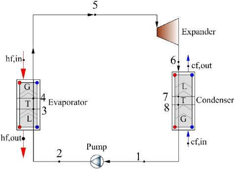
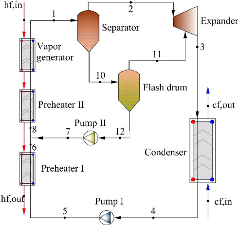
The ORC flow diagram is illustrated in Figure 1. It mainly includes evaporator, expander, condenser, and working fluid pump. And the system description and the thermodynamic model can be referred in Basaran and Ozgener, (2013). The BFC flow diagram is shown in Figure 2. It is composed of preheater, vapor generator, gas-liquid separator, expander, flash drum, condenser, working fluid pump. The geothermal brine from the production well enters into the vapor generator and heats the R245fa. It should be noted that the R245fa is heated to a gas-liquid state, which is the largest difference with the ORC system. The gas-liquid two-phase R245fa is fed into the separator. The gas-phase R245fa from the separator is sent to the high-pressure-stage expander to produce power. The remaining liquid-phase R245fa from the separator flows into the flash drum through the throttle value. The flashed gas-phase R245fa flows into the low-pressure-stage expander to produce work again. The liquid R245fa released from the flash drum is pressurized into preheater II to absorb the heat of the geothermal brine from the vapor generator. The R245fa from the expander is driven toward the condenser, at which it is condensed to liquid state by rejecting heat to the cooling water. And then R245fa is pressurized into preheater I, where it absorbs the heat of the geothermal brine from preheater II. The left geothermal water is reinjected to the injection well. Finally, R245fa from preheater II flows into the vapor generator.
2.2 Thermo-Economic Model
To simplify the ORC and BFC system model, the following assumptions are listed as follows (Van et al., 2014).
1) Both the ORC and the BFC are modeled under steady state;
2) Pressure loss of each component is neglected except for the turbine and the pump;
3) Friction losses, heat dissipation, kinetic energy, and potential energy are ignored;
4) The irreversibility related to the separator is ignored;
5) Plate-type heat exchangers are adopted;
6) The geothermal water is assumed to be pure water;
7) The pinch point temperature differences of the evaporator and the condenser are set to be 10 and 5°C, respectively.
2.2.1 Thermodynamic Model
The heat balance in the preheater I, preheater II, and vapor evaporator yields the following expression:
The heat transferred in preheater I is given by
The heat transferred in preheater II is given by
The heat transferred in vapor evaporator is given by
The total input heat into the BFC is given by
where Q denotes heat transfer rate, kW; cp denotes specific heat capacity, kJ/(kg·K); T represents temperature, °C; h denotes the specific enthalpy, kJ/kg; the subscripts “hf,” “wf,” “Pre1,” “Pre2,” “in,” “out,” “gen,” and “tot” denote geothermal brine, R245fa, preheater I, preheater II, inlet, outlet, vapor generator, and total, respectively. The subscript numbers represent the BFC working state points shown in Figure 2.
The heat transferred in the condenser is given by
where the subscripts “con” and “cf” denote the condenser and cooling water, respectively.
Mass balance equations of BFC are given by
where m is the mass flow rate, kg/s; qu is the dryness degree of the working fluid at the evaporator outlet. The subscript “fsh” is the flash drum.
The power output in the high-pressure stage of the expander is given by:
where the subscripts “exp” and “s” denote expander and isentropic, respectively.
The consumed power of the working fluid pump I is given by:
The consumed power of the working fluid pump II is given by:
where the subscript “pp” denotes the working fluid pump.
The net power output of the BFC is given by
where the subscript “net” denotes net power output.
The thermal efficiency is expressed by:
The input exergy is defined as:
Considering the inherent qualitative difference between heat and mechanical power, the exergy analysis is applied to analyze the quality of energy or the potential of thermal energy. The exergy efficiency is given by:
The heat recovery rate is used to indicate the utilization degree of geothermal water, as given by:
where UR is the heat recovery rate; ppeva is pinch point temperature difference, °C.
2.2.2 Plate-Type Heat Exchanger Model
The plate-type heat exchangers are applied as the evaporator and the condenser due to the compactness, flexibility, higher heat transfer coefficient, and lower refrigerator charge. And the heat transfer area of the evaporator is calculated sectionalized.
The heat transfer rate of the evaporator is given by:
where U is the overall heat transfer coefficient, W/(m2·°C); A is the heat transfer area, m2; ΔTm is the log mean temperature difference between the geothermal brine and R245fa, °C.
The heat transfer coefficient of the plate-type heat exchanger can be calculated by:
where αi,hs is the heat transfer coefficient on the geothermal brine side, W/(m2·°C); δ is the plate-type heat exchanger fin thickness, m; λ is heat conductivity coefficient, W/(m·°C); αi,cs is the heat transfer coefficient on the R245fa side, W/(m2°C).
The heat transfer coefficient of the single-phase flow section is obtained by the following equation (Chisholm and Wanniarachchi, 1992).
where dh is hydraulic diameter, m; β is plate-type heat exchanger corrugation angle, °; Nu is Nusselt number; Re is Reynolds number; Pr is Prandtl number.
where G is R245fa mass velocity, kg/(m2·s); μ is viscosity, Pa·s.
The convection heat transfer coefficient of the gas-liquid two-phase fluid is calculated by the correlation presented by Yan and Lin (1999).
where xm denotes the R245fa vapor quality, the subscript “eq” denotes equivalent.
The heat transfer area of the condenser is also calculated sectionalized.
The heat transfer coefficient of the single-phase flow region is obtained by Eq. 24. The convection heat transfer coefficient of the condenser two-phase flow region is given by
2.2.3 Economic Model
The chemical engineering plant cost (CEPCI) model is used to conduct economic analysis. The investment cost of the heat exchangers is given by (Hou et al., 2018):
where Chx is the heat exchanger investment cost, $; CEPCI2001 and CEPCI2019 are 2001 and 2019 chemical engineering plant cost index, respectively; Fs is an additional factor; Chx0 is the basic investment cost, $; B1,hx,B2,hx are the constants; Fm,hx is the material factor; Fp,hx is the pressure factor.
where K1,hx,K2,hx, C1,hx,C2,hx, and C3,hx are the constants; Ahx is the plate-type heat exchanger heat transfer area, m2; Phx is the plate-type heat exchanger design pressure, bar.
The working fluid pump investment cost is given by:
where Cpp is working fluid pump capitalized cost, $; Fm,pp is an additional factor; Fp,pp is pressure factor, which is calculated as follows; Cpp0 is the basic cost that is calculated as follows, $;
where B1,pp, B2,pp, K1,pp, K2,pp,K3,pp, C1,pp, C2,pp, and C3,pp are the constants; Ppp is the pressure, bar; Wpp is the consumed power, kW.
The expander investment cost is given by:
where Cexp is investment cost of expander, $; Fm,exp is pressure factor; Cexp0 is the basic cost; K1,exp, K2,exp, K3,exp are the constants.
The investment cost of the separator and the flashing tank is given by (Chisholm and Wanniarachchi, 1992):
where Csep and Cfsh are investment costs of the separator and the flashing tank, respectively, $; V is the volume, m3.
The investment cost of the circulating water pump is given by (Yan and Lin, 1999):
where Wwatpp is the consumed mechanical power, kW; g is the acceleration of gravity, m/s2; Hwatpp is the hydraulic head, m; ηwatpp is the efficiency of the water pump.
The total investment cost is given by:
where Cwell is the mining rights cost, $.
The operation and maintenance cost is given by (Hou et al., 2018):
The operation cost of the circulating water pump is given by:
where Cele is unitary cost of the electricity, $/kW; TPY is the annual operating time, h.
In consideration of time value of money, the payback period is calculated by:
where pb is payback period, year; i is interest rate, assumed to be 5%.
The input parameters of CEPCI model are listed in Table 2.
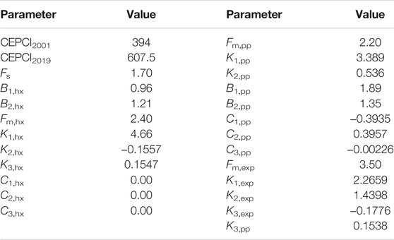
TABLE 2. Input parameters of CEPCI model (Imran et al., 2014; Hou et al., 2018).
Based on the established thermo-economic model above, all the codes were developed. The R245fa thermo-properties are obtained by NIST REFPROP 9.0 (Lemmon et al., 2013).
3 Model Validation
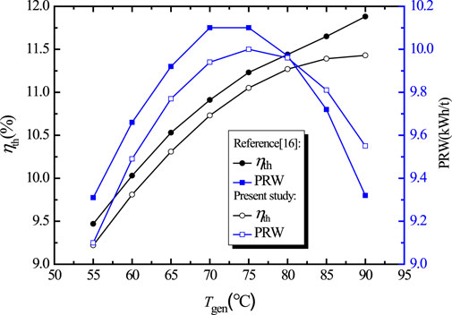
Based on the present and Wang et al. (2016) thermodynamic model, the variations of thermal efficiency (ηth) and net power output per ton of geothermal water (PRW) against generation temperature (Tgen) under the same operating conditions are illustrated in Figure 3. As can be seen, the maximum deviations of ηth and PRW between the results of the present model and Wang et al. (2016). are less than 3.8 and 2.5%, respectively. The comparison shows a good agreement between the present model and Wang et al. (2016). That is to say the present model can be used to simulate the system performance within an acceptable error range.
4 Results and Discussion
4.1 Thermo-Economic Comparison Between ORC and BFC
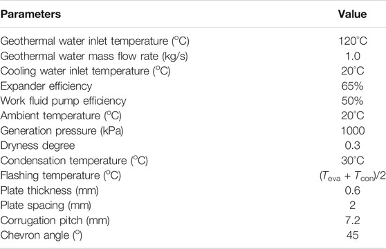
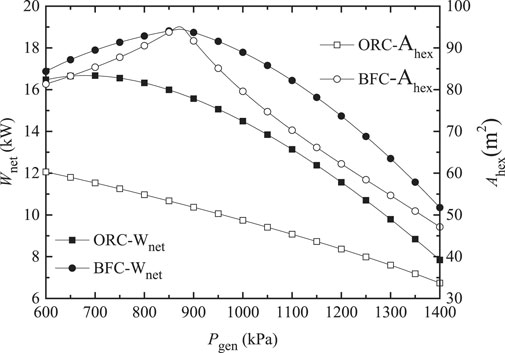
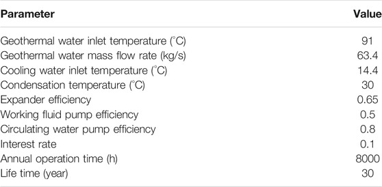
Based on the model developed above, the thermo-economic comparison between ORC and BFC is conducted. The typical input parameters and boundary conditions investigated are listed in Table 3. Note that the given efficiencies of the expander and the pump are far lower than those set in literatures (Meng et al., 2017; Yang et al., 2017), which will be more closer to reality. The variations of Wnet and Ahex for the ORC and BFC with generation pressure (Pgen) are displayed in Figure 4. As can be seen, with the rising of Pgen, both the Wnet, and Ahex of the ORC are decreased, while the Wnet and Ahex of the BFC first increase and then decrease. The ORC and BFC have different operating characteristics. The variation of Wnet for the BFC is mainly due to that for a specific condensation temperature, an increase in Pgen leads to rising of the specific enthalpy drop across the expander, but meanwhile it will drop the working fluid mass flow rate. With the interaction between the two influences, an optimal Pgen exists and maximizes Wnet, which is well in conformity with the results reported by Edrisi and Michaelides (2013). The optimal Pgen is 870 kPa, at which Wnet and Ahex achieve the maximum. As can be seen the Wnet and Ahex of the BFC are always higher than those of the ORC. With the rising of Pgen, the ratio of Wnet of BFC to that of ORC increases basically linearly. The Wnet of BFC is 32% larger than that of ORC with Pgen of 1400 kPa. Nevertheless, the ratio of Ahex of the BFC to that of the ORC first rises then declines, after reaching the peak value (1.8) at 870 kPa. To sum up, the BFC produces more work compared with the ORC. In the meantime, the heat exchangers investment cost of the BFC is much larger.
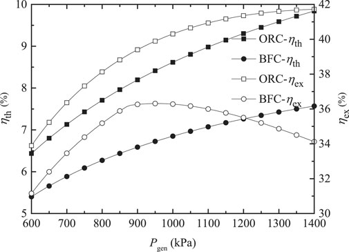
The variations of ηth and ηex for the ORC and BFC with Pgen are depicted in Figure 5. As expected, the ηth of the ORC and the BFC increase with the rising Pgen, presenting the same behavior. The ηex of the ORC is increased as Pgen increases. While the ηex of the BFC first rises and subsequently decreases, and an optimum Pgen (950 kPa) occurs, at which the ηex obtains the maximum value. The dryness degree of the working fluid at the evaporator exit is a fixed constant in the present study. The heat transfer temperature difference between the working fluid and the geothermal water is decreased with the increasing Pgen, leading to the rising of the reinjection temperature of geothermal water. As a consequence, the input exergy is decreased. The variation of Wnet with Pgen has been already shown in Figure 4. With the interaction between the two effects, there exists an optimum Pgen at which the ηex obtains the maximum value. It is obvious that the ηth and ηex of the ORC are higher than those of the BFC. When Pgen is 1100 kPa, the ηth and ηex of the ORC are 1.26 and 1.14 times as large as those of the BFC.
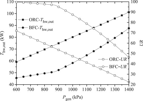
The heat recovery efficiency is an important indicator for the low-grade waste heat utilization system. For the nonflowing geothermal energy, the acquiring of geothermal water requires a lot of power consumption for the geothermal water pump. Full use of the geothermal water is beneficial. It is of practical significance to evaluate the system performance with the heat recovery efficiency as criteria. The variations of geothermal water injection temperature (Tth,out) and heat recovery rate (UR) for the ORC and BFC with Pgen are depicted in Figure 6. As can be discovered, the Tth,out of the BFC is 15–20°C lower than that of the ORC. And the UR of BFC is always much larger than that of ORC. The UR of BFC is 1.96 times as much as that of ORC. As can be seen, the BFC can achieve the full use of low-grade energy. After comprehensive consideration, the BFC system obtains the larger net power output, sacrificing its efficiency.
4.2 Case Study of the ORC and BFC in Fengshun Geothermal Plant
The first geothermal power generation station with a capacity of 300 kW was established in 1970 in Dengwu village of Fengshun county, Guangdong province, which was established by the Guangzhou Institute of Energy Conversion. The establishment of Fengshun power plant marked that China became the 8th country owning the geothermal energy power generation technology for realistic operation. The geothermal well is approximately 800 m deep and produces geothermal water at 91°C. The geothermal water is pumped to the flashing tank with the mass flow rate of 63.4 kg/s. The cooling water from the river nearby is used to cool the turbine exhaust. The power station had retired since the last year and finished the historical mission. From the above-mentioned investigation, the BFC has the advantage of higher utilization rate of geothermal water compared with the ORC due to lower reinjection temperature. The preliminary economic feasibility study of BFC will be investigated based on working condition in Fengshun power plant. The input parameters of the economic simulation are listed in Table 4. The economic comparison of the ORC and BFC is presented in Table 5. As can be seen, the total investment cost, maintenance cost, and electric charge of circulating water pump for the BFC are all higher than those of the ORC. Meanwhile, with the Pgen of 600, 700, and 740 kPa, the Wnet of the BFC is 1.26, 1.41, and 1.68 times as large as those of ORC, and compared with the ORC, the payback period of the BFC is shortened by 1.9, 3.5, and 7.4 years, respectively. The payback period of BFC is just 6.0 years under the Pgen of 600 kPa. It is indicated that the BFC exhibits better economic benefits.
5 Conclusion
In the present article, the thermo-economic comparison between the ORC and BFC for geothermal energy is conducted. The main contribution is the performance contrast from the viewpoint of thermodynamic and economic, simutaneously. And the preliminary discussion of the economic feasibility of BFC system applying in FengShun geothermal field. According to the investigation, several conclusions can be drawn as follows:
1) With the rising generation pressure, the net power output and the heat exchanger area of the BFC first increase and then decrease. There exists the optimum generation pressure for the BFC. The BFC has larger net power output and heat exchanger area than ORC.
2) The ORC and BFC yield different operating characteristics. The thermal efficiency and exergy efficiency of ORC are 1.26 and 1.14 times as large as those of the BFC with the generation pressure of 1,100 kPa.
3) The geothermal tail water temperature of the BFC is much lower than that of the ORC, approximately 15–20°C. The heat recovery rate of the BFC is always much larger than that of the ORC. The heat recovery rate of BFC is 1.96 times as much as that of the ORC.
4) With the Fengshun power plant as a case study, under the generation pressure of 600, 700, and 740 kPa, the net power output of the BFC is 1.26, 1.41, and 1.68 times as large as those of the ORC, and compared with the ORC, the payback period of the BFC is shortened by 1.9, 3.5, and 7.4 years, respectively. The payback period of BFC is only 6.0 years under the generation pressure of 600 kPa. It is indicated that the BFC exhibits excellent economic benefits, especially in the nonflowing geothermal well (Berhane et al., 2009; Mosaffa et al., 2016; Zhao and Wang, 2016; Rayegan and Tao, 2011).
Data Availability Statement
The raw data supporting the conclusions of this article will be made available by the authors, without undue reservation.
Author Contributions
YZ: Conceptualization. BD: Formal analysis. SC: Methodology. JZ: Investigation. YG: Writing—review and editing. XB: Supervision. HL: Software, Writing—review and editing. LW: Methodology, Writing—original draft.
Conflict of Interest
YZ, BD, and SC were employed by the company Powerchina HuaDong Engineering Corporation Limited.
The remaining authors declare that the research was conducted in the absence of any commercial or financial relationships that could be construed as a potential conflict of interest.
Publisher’s Note
All claims expressed in this article are solely those of the authors and do not necessarily represent those of their affiliated organizations, or those of the publisher, the editors and the reviewers. Any product that may be evaluated in this article, or claim that may be made by its manufacturer, is not guaranteed or endorsed by the publisher.
Acknowledgments
The authors gratefully acknowledge the financial supports provided by the Natural Science Foundation of Guangdong Province (No. 2021A1515011763), Science and Technology Plan Project of Guangzhou (No. 202102020301) and China Postdoctoral Science Foundation (No. 2020M681799).
References
Astolfi, M., Romano, M. C., Bombarda, P., and Macchi, E. (2014). Binary ORC (Organic Rankine Cycles) Power Plants for the Exploitation of Medium-Low Temperature Geothermal Sources - Part B: Techno-Economic Optimization. Energy 66, 435–446. doi:10.1016/j.energy.2013.11.057
Basaran, A., and Ozgener, L. (2013). Investigation of the Effect of Different Refrigerants on Performances of Binary Geothermal Power Plants. Energ. Convers. Manage. 76, 483–498. doi:10.1016/j.enconman.2013.07.058
Berhane, H. G., Gonzalo, G. G., Laureano, J., and Dieter, B. (2009). Design of Environmentally Conscious Absorption Cooling Systems via Multi-Objective Optimization and Life Cycle Assessment. Appl. Energ. 86, 1712–1722. doi:10.1016/j.apenergy.2008.11.019
Cao, Y., and Dai, Y. (2017). Comparative Analysis on Off-Design Performance of a Gas Turbine and ORC Combined Cycle under Different Operation Approaches. Energ. Convers. Manage. 135, 84–100. doi:10.1016/j.enconman.2016.12.072
Chisholm, D., and Wanniarachchi, A. S. (1992). Maldistribution in Single-Pass Mixed- Channel Plate Heat Exchangers. Compact Heat Exchangers Power Process. Industries, Htd-asme 201, 95–99.
Edrisi, B. H., and Michaelides, E. E. (2013). Effect of the Working Fluid on the Optimum Work of Binary-Flashing Geothermal Power Plants. Energy 50, 389–394. doi:10.1016/j.energy.2012.10.025
Franco, A., and Vaccaro, M. (2014). Numerical Simulation of Geothermal Reservoirs for the Sustainable Design of Energy Plants: a Review. Renew. Sustain. Energ. Rev. 30, 987–1002. doi:10.1016/j.rser.2013.11.041
Hou, S., Zhou, Y., Yu, L., Zhang, F., and Cao, S. (2018). Optimization of the Combined Supercritical CO2 Cycle and Organic Rankine Cycle Using Zeotropic Mixtures for Gas Turbine Waste Heat Recovery. Energ. Convers. Manage. 160, 313–325. doi:10.1016/j.enconman.2018.01.051
Imran, M., Park, B. S., Kim, H. J., Lee, D. H., Usman, M., and Heo, M. (2014). Thermo-economic Optimization of Regenerative Organic Rankine Cycle for Waste Heat Recovery Applications. Energ. Convers. Manage. 87, 107–118. doi:10.1016/j.enconman.2014.06.091
Kong, Y., Pang, Z., Shao, H., Hu, S., and Kolditz, O. (2014). Recent Studies on Hydrothermal Systems in China: a Review. Geotherm Energy 2, 19. doi:10.1186/s40517-014-0019-8
Lemmon, E. W., Huber, M. H., and McLinden, M. O. (2013). REFPROP, NIST Standard Reference Database 23. USA: National Institute of Standards and Technology. Version 9.1.
Li, T., Yuan, Z., Li, W., Yang, J., and Zhu, J. (2016). Strengthening Mechanisms of Two-Stage Evaporation Strategy on System Performance for Organic Rankine Cycle. Energy 101, 532–540. doi:10.1016/j.energy.2016.02.068
Li, Y.-M., Hung, T.-C., Wu, C.-J., Su, T.-Y., Xi, H., and Wang, C.-C. (2021). Experimental Investigation of 3-kW Organic Rankine Cycle (ORC) System Subject to Heat Source Conditions: A New Appraisal for Assessment. Energy, 2021, 217:119342. doi:10.1016/j.energy.2020.119342
Liu, X., Li, H., Bu, X., Wang, L., Xie, N., and Zeng, J. (2018). Performance Characteristics and Working Fluid Selection for Low-Temperature Binary-Flashing Cycle. Appl. Therm. Eng. 141, 51–60. doi:10.1016/j.applthermaleng.2018.05.106
Mallapaty, S. (2020). How China Could Be Carbon Neutral by Mid-century. Nature 586, 482–483. doi:10.1038/d41586-020-02927-9
Meng, F., Zhang, H., Yang, F., Hou, X., Lei, B., Zhang, L., et al. (2017). Study of Efficiency of a Multistage Centrifugal Pump Used in Engine Waste Heat Recovery Application. Appl. Therm. Eng. 110, 779–786. doi:10.1016/j.applthermaleng.2016.08.226
Miao, Z., Xu, J., and Zhang, K. (2017). Experimental and Modeling Investigation of an Organic Rankine Cycle System Based on the Scroll Expander. Energy 134, 35–49. doi:10.1016/j.energy.2017.06.001
Michaelides, E. E. (2016). Future Directions and Cycles for Electricity Production from Geothermal Resources. Energ. Convers. Manage. 107, 3–9. doi:10.1016/j.enconman.2015.07.057
Michaelides, E. E., and Scott, G. J. (1984). A Binary-Flashing Geothermal Power Plant. Energy 9, 323–331. doi:10.1016/0360-5442(84)90103-8
Mosaffa, A. H., Garousi Farshi, L., and Farshi, L. G. (2016). Exergoeconomic and Environmental Analyses of an Air Conditioning System Using thermal Energy Storage. Appl. Energ. 162, 515–526. doi:10.1016/j.apenergy.2015.10.122
Rayegan, R., and Tao, Y. X. (2011). A Procedure to Select Working Fluids for Solar Organic Rankine Cycles (ORCs). Renew. Energ. 36, 659–670. doi:10.1016/j.renene.2010.07.010
Shi, H., and Michaelides, E. E. (1989). Binary Dual-Flashing Geothermal Power Plants. Int. J. Energ. Res. 13, 127–135. doi:10.1002/er.4440130202
Sun, X., Liu, L., Dong, Y., Zhuang, Y., Li, J., Du, J., et al. (2021). Multi-objective Optimization and Thermo-Economic Analysis of an Enhanced Compression-Absorption cascade Refrigeration System and ORC Integrated System for Cooling and Power Cogeneration. Energ. Convers. Manage. 236, 114068. doi:10.1016/j.enconman.2021.114068
Van, L. L., Michel, F., Abdelhamid, K., and Sandrine, P. P. (2014). Performance Optimization of Low-Temperature Power Generation by Supercritical ORCs (Organic Rankine Cycles) Using Low GWP (Global Warming Potential) Working Fluids. Energy 67, 513–526. doi:10.1016/j.energy.2013.12.027
Wang, L., Bu, X., and Li, H. (2019). Investigation on Geothermal Binary-Flashing Cycle Employing Zeotropic Mixtures as Working Fluids. Geotherm Energy 7 (1), 36. doi:10.1186/s40517-019-0153-4
Wang, L., Bu, X., Li, H., Wang, H., and Ma, W. (2018). Working Fluids Selection for Flashing Organic Rankine Regeneration Cycle Driven by Low-Medium Heat Source. Environ. Prog. Sustain. Energ. 37, 1201–1209. doi:10.1002/ep.12774
Wang, Y. X., Wang, L. B., Li, H. S., and Bu, X. B. (2016). Thermodynamic Calculation and Optimization of Geothermal Power Generation in Ganzi. J. Harbin Eng. Univ. 37, 873–877. doi:10.11990/jheu.201504026
Yan, Y.-Y., and Lin, T.-F. (1999). Evaporation Heat Transfer and Pressure Drop of Refrigerant R-134a in a Plate Heat Exchanger. J. Heat Transfer 121, 118–127. doi:10.1115/1.2825924
Yang, M.-H., Yeh, R.-H., and Hung, T.-C. (2017). Thermo-economic Analysis of the Transcritical Organic Rankine Cycle Using R1234yf/R32 Mixtures as the Working Fluids for Lower-Grade Waste Heat Recovery. Energy 140, 818–836. doi:10.1016/j.energy.2017.08.059
Yu, S., Hu, X., Li, L., and Chen, H. (2020). Does the Development of Renewable Energy Promote Carbon Reduction? Evidence from Chinese Provinces. J. Environ. Manage. 268, 110634. doi:10.1016/j.jenvman.2020.110634
Yuan, Z., and Michaelides, E. E. (1993). Binary-flashing Geothermal Power Plants. J. Energ. Resour. Tech. 115, 232–236. doi:10.1115/1.2905999
Zhao, Y., and Wang, J. (2016). Exergoeconomic Analysis and Optimization of a Flash-Binary Geothermal Power System. Appl. Energ. 179, 159–170. doi:10.1016/j.apenergy.2016.06.108
Nomenclature
Symbols
A area (m2)
Bo boiling number
C investment cost ($)
cp specific heat capacity (kJ/kg·K−1)
Dh hydraulic diameter (m)
E available solar exergy (kW)
g acceleration of gravity (m/s2)
G mass velocity (kg/(m2 s))
h specific enthalpy (kJ/kg), convection heat transfer coefficient (W/m2·K−1)
H hydraulic head (m)
i interest rate
m mass flow rate (kg/s)
Nu Nusselt number
P pressure (kPa)
pb payback period (year)
pp pinch point temperature difference (oC) working fluid pump
Pr Prandtl number
Q heat transfer rate (kW)
qu dryness degree of the working fluid
R thermal resistance
Re Reynolds number
T temperature (oC)
TPY annual operating time (h)
U overall heat transfer coefficient (W/(m2·K))
UR heat recovery rate
V volume
W work (kW)
x quality of the working fluid
ΔT logarithmic temperature difference (°C)
Greek
η efficiency
α heat transfer coefficient (W/(m2·K))
λ coefficient of thermal conductivity (W/(m·K))
β corrugation anlge (°)
ρ density (kg/m3)
μ viscosity (Pa·s)
ε isotropic efficiency
Φ enlargement factor of the corrugated plates
Subscripts
1, 2,…, 4 state points
cf cooling water
cs cold fluid side
con condenser
ele electriciy
eq equivalent
eva evaporator
ex exergy
exp expander
fsh flash drum
gen vapor generator
hs hot fluid side
hx heat exchanger
in inlet
net net power output
om operation and maintenance
out outlet
pp working fluid pump
s isentropic process
sep separator
tot total
th thermal
watpp water pump
well well
wf working fluid
Acronyms
BFC binary flashing cycle
CEPCI chemical engineering plant cost index
GWP global warming potential
ORC Organic Rankine Cycle
ODP ozone depletion potential
Keywords: geothermal energy, organic Rankine cycle, binary flashing cycle, thermo-economic, payback period
Citation: Zhao Y, Du B, Chen S, Zhao J, Gong Y, Bu X, Li H and Wang L (2021) Thermo-Economic Comparison Between Organic Rankine Cycle and Binary-Flashing Cycle for Geothermal Energy. Front. Earth Sci. 9:759872. doi: 10.3389/feart.2021.759872
Received: 17 August 2021; Accepted: 15 September 2021;
Published: 07 October 2021.
Edited by:
Yanlong Kong, Institute of Geology and Geophysics (CAS), ChinaReviewed by:
Tailu Li, Hebei University of Technology, ChinaTiantian Zhang, Harbin Institute of Technology, China
Copyright © 2021 Zhao, Du, Chen, Zhao, Gong, Bu, Li and Wang. This is an open-access article distributed under the terms of the Creative Commons Attribution License (CC BY). The use, distribution or reproduction in other forums is permitted, provided the original author(s) and the copyright owner(s) are credited and that the original publication in this journal is cited, in accordance with accepted academic practice. No use, distribution or reproduction is permitted which does not comply with these terms.
*Correspondence: Lingbao Wang, d2FuZ2xiQG1zLmdpZWMuYWMuY24=
 Yuan Zhao1,2
 Yulie Gong
 Lingbao Wang
